
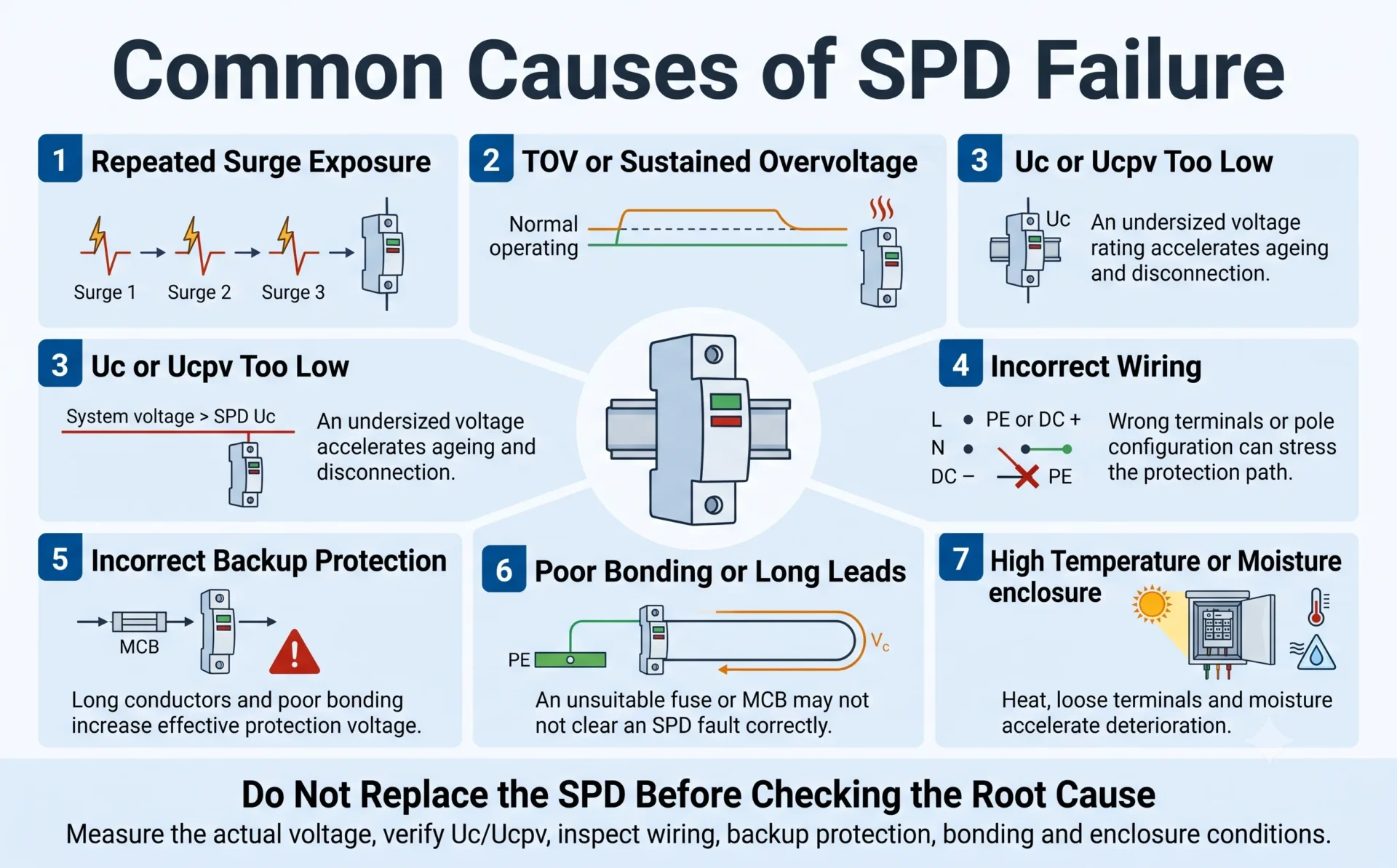
As causas mais comuns de falha do SPD são estresse por picos repetidos, sobretensão temporária, seleção incorreta de Uc ou Ucpv, erros de fiação, proteção de backup inadequada, temperatura excessiva, umidade e o uso do dispositivo de proteção contra surtos errado para o sistema.
Um raio é apenas uma possível causa. Um dispositivo de proteção contra surtos também pode falhar prematuramente porque a tensão operacional real é maior do que o esperado, uma falha no neutro cria tensão anormal, um array fotovoltaico excede o Ucpv selecionado ou o SPD é instalado sob condições elétricas ou ambientais inadequadas.
Para as equipes de manutenção, a questão importante não é apenas “O SPD falhou?” É também “Por que ele falhou, e o SPD de substituição falhará novamente?”
Escopo deste guia: Esta página explica por que os SPDs falham e por que os módulos de substituição às vezes falham novamente. Para procedimentos de inspeção passo a passo, veja Como Verificar a Falha do SPD. . Para a substituição de cartuchos de encaixe, use o guia de substituição relacionado.
Índice
O que causa a falha de um SPD?
Um SPD pode falhar após exposição acumulada a surtos, um evento acima de sua capacidade de descarga, uma sobretensão temporária ou outra condição anormal de tensão sustentada, Uc ou Ucpv selecionado abaixo da tensão real do sistema, fiação incorreta, proteção de backup de corrente de falha inadequada, alta temperatura da caixa, umidade ou uma aplicação incorreta de CA ou CC de PV.
Se um novo SPD de substituição falhar novamente, não continue trocando cartuchos sem investigar o sistema. Meça a tensão real, verifique o rótulo do SPD e a aplicação, confira o neutro e a fiação, inspecione o fusível de backup ou MCB, e examine a base, terminais e condições da caixa.
| Causa possível | O que pode acontecer | O que as equipes de manutenção devem verificar |
|---|---|---|
| Exposição repetida a surtos | Os componentes MOV envelhecem gradualmente após estresse elétrico e térmico acumulado. | Exposição a relâmpagos, eventos de comutação, histórico de surtos e registros de substituição. |
| Surtos acima da capacidade do SPD | Um evento severo pode causar degradação imediata ou operar o desconector interno. | Tipo de SPD, In, Imax ou Iimp, posição de instalação e conceito de proteção contra relâmpagos. |
| Sobretensão temporária ou anormal | O SPD pode operar por tempo demais, gerar calor e desconectar. | L-N, L-PE, N-PE ou tensão CC, condição de neutro, transformador, gerador e anomalias de rede. |
| Uc ou Ucpv muito baixo. | A tensão de operação normal ou variação esperada pode acelerar o envelhecimento do varistor. | Tensão máxima contínua, arranjo de aterramento, PV Voc e correção de baixa temperatura. |
| Fiação ou aplicação incorretas. | Um modo de proteção pode carregar tensão anormal ou o caminho de proteção pretendido pode não operar corretamente. | Designação de terminais, polaridade, configuração de polos, arranjo N-PE e aplicação de CC PV versus AC. |
| Proteção de backup incorreta. | Uma falha de frequência de energia pode não ser eliminada corretamente, ou o dispositivo a montante pode disparar desnecessariamente. | Classificação do fusível ou MCB, capacidade de interrupção, corrente de curto-circuito e requisitos do fabricante. |
| Condutores longos ou ligação equipotencial deficiente | O desempenho da proteção pode ser reduzido e o equipamento pode apresentar uma tensão residual efetiva mais elevada. | Continuidade do PE, ligação equipotencial, comprimento do condutor, roteamento e aperto dos terminais. |
| Alta temperatura ou umidade | O envelhecimento térmico, a corrosão, a deterioração do isolamento e o aquecimento dos terminais podem ser acelerados. | Temperatura do invólucro, ventilação, luz solar, condensação, proteção IP e terminais frouxos. |
| Problema de produto ou de lote | Os componentes, as conexões ou os mecanismos de desconexão podem não funcionar conforme declarado. | Se falhas semelhantes aparecem em um mesmo lote de produção ou em diferentes instalações, sob condições normais verificadas. |
Causa, mecanismo de falha e resultado visível não são a mesma coisa
Uma investigação útil da causa raiz de um SPD separa quatro níveis diferentes. O indicador vermelho visível costuma ser o resultado final, não a causa original.
| Causa raiz | Mecanismo de falha | Resposta de proteção | Resultado visível |
|---|---|---|---|
| Neutro desconectado ou instável | A tensão aplicada excede a faixa normal de operação e o MOV conduz por tempo excessivo. | A temperatura interna sobe e o desconector térmico abre. | A janela de estado muda, o contato remoto muda de estado ou o SPD fica desconectado. |
| Exposição repetida a surtos | As características do MOV mudam gradualmente após estresse elétrico e térmico acumulado. | A fuga de corrente e o aquecimento aumentam até que o elemento de proteção seja isolado. | A indicação de fim de vida aparece após um evento posterior ou durante a operação. |
| Um evento acima da capacidade do SPD | O componente de proteção sofre energia de impulso excessiva. | O seccionador atua ou a proteção contra falha a montante interrompe o circuito. | Podem ocorrer indicação imediata, disparo da proteção ou danos visíveis. |
Um indicador vermelho identifica a condição do SPD, não a causa raiz
A equipe de manutenção ainda precisa determinar se a causa original foi envelhecimento normal por surtos acumulados, tensão anormal do sistema, seleção incorreta, condições de instalação ou um possível problema do produto.
1. Picos repetidos envelhecem gradualmente o SPD
Muitos SPDs limitadores de tensão usam varistores de óxido metálico. Durante um surto, o varistor passa de um estado de alta impedância para um estado condutivo e limita a tensão transitória no circuito protegido.
Cada operação significativa cria estresse elétrico e térmico. Um evento pequeno pode ter pouco efeito mensurável, enquanto eventos repetidos ou de maior energia podem alterar gradualmente as características do MOV, aumentar a corrente de fuga e reduzir a margem de operação restante.
Com o tempo, o seccionador térmico interno pode isolar o componente de proteção e o indicador visual ou o contato remoto pode mudar de estado.
Não existe um número universal de descargas atmosféricas para um SPD
A vida útil de serviço do SPD não pode ser prevista apenas pela contagem de eventos de raios. Um surto de comutação de baixa energia e uma corrente de raio de alta energia não impõem o mesmo estresse ao dispositivo. Forma de onda, amplitude, duração, distribuição de corrente, classificação do SPD, posição de instalação e degradação prévia afetam o resultado.
Um SPD relativamente novo pode falhar durante um único evento severo. Um SPD mais antigo pode permanecer operacional após muitos eventos menores. Um contador de surtos, portanto, não pode fornecer uma porcentagem exata da vida útil restante do SPD.
2. Um pico pode exceder a capacidade de descarga do SPD
Um SPD não é um absorvedor ilimitado de energia. Suas correntes nominais declaradas descrevem o desempenho sob formas de onda e condições de teste especificadas.
Os SPDs Tipo 2 normalmente declaram corrente nominal de descarga Em e corrente máxima de descarga Imax. Os SPDs Tipo 1 declaram corrente de impulso Iimp.
Se um evento real for mais severo do que o dispositivo, a posição de instalação ou o conceito de proteção podem suportar, o SPD pode se desconectar imediatamente, sofrer degradação interna ou perder a proteção sem danos externos dramáticos.
Um SPD Tipo 2 que falha próximo à entrada de serviço não é automaticamente defeituoso. O projeto pode ter exigido um SPD Tipo 1 ou Tipo 1+2, uma classificação de corrente diferente, condutores mais curtos ou melhor coordenação com outros estágios de proteção.
Não diagnostique a capacidade contra surtos com base apenas no Imax
O tipo e a classificação corretos do SPD dependem da posição de instalação, da exposição a descargas atmosféricas, da presença de um sistema externo de proteção contra raios, do tipo de alimentação de entrada e da coordenação com os SPDs a jusante. Veja o Guia de Seleção Imax de SPD .
3. Sobretensão temporária não é a mesma coisa que um pico de raios
Muitas falhas prematuras ou repetidas de SPD são atribuídas a raios quando a causa real é uma sobretensão temporária ou outra condição anormal de tensão que permanece presente por muito mais tempo do que um surto transitório.
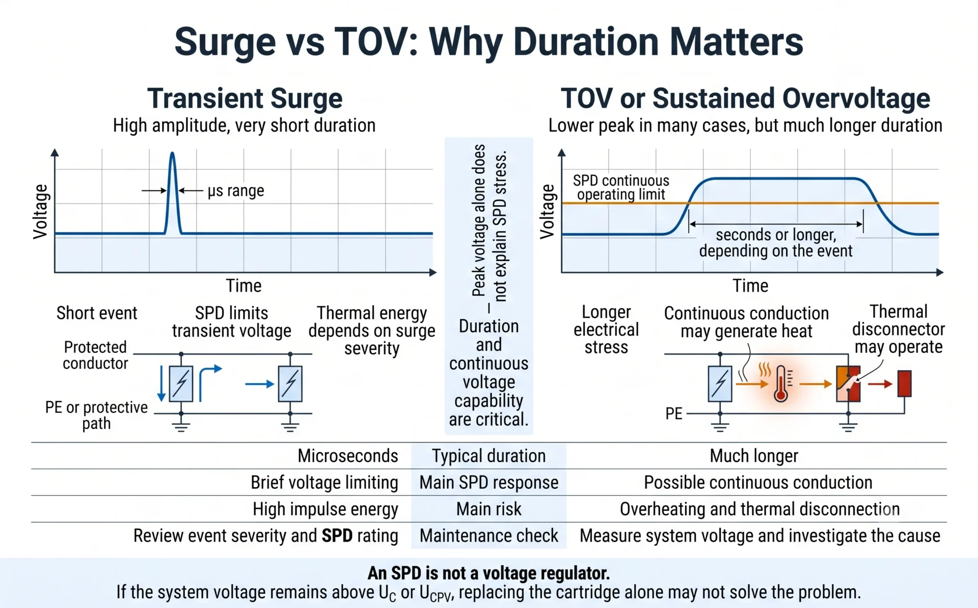
Um surto transitório pode ter um pico muito alto, mas durar apenas microssegundos. Uma sobretensão temporária geralmente tem um pico menor do que um impulso atmosférico, mas permanece presente por muito mais tempo.
Um dispositivo de proteção contra surtos é projetado para limitar sobretensões transitórias de curta duração. Ele não foi concebido para operar continuamente como um regulador de tensão.
Se a tensão aplicada permanecer acima da faixa de operação contínua do SPD, o componente limitador de tensão pode conduzir por tempo excessivo, gerar calor e acionar seu desconector térmico.
Um SPD em conformidade deve ter uma resposta definida a sobretensões temporárias especificadas. Dependendo do projeto declarado, ele pode suportar a condição ou atingir um estado controlado de fim de vida. Isso não significa que possa limitar com segurança, por tempo indeterminado, qualquer tensão anormal sustentada.
Possíveis fontes de tensão anormal
- Condutor neutro solto, danificado ou desconectado.
- Configuração incorreta da tomada do transformador.
- Problema de regulação de tensão do gerador.
- Desequilíbrio de fase ou outra falha na rede.
- Conexão incorreta do condutor de fase, neutro ou de proteção.
- Falha à terra do sistema fotovoltaico, falha de isolamento ou tensão inesperada entre condutor e terra.
- Tensão do sistema consistentemente mais alta do que a assumida durante a seleção do SPD.
Substituir o cartucho não elimina a tensão anormal
Se a falha original foi causada por um problema no neutro, TOV ou outra condição de tensão anormal sustentada, um cartucho de substituição com a mesma classificação também pode superaquecer e desligar. Meça e corrija a condição do sistema antes de instalar repetidamente novos cartuchos.
4. Uc ou Ucpv foi selecionado abaixo da tensão operacional real
Uc é a tensão máxima contínua de operação declarada para um SPD em CA. Para SPDs fotovoltaicos, o parâmetro CC correspondente é comumente mostrado como Ucpv.
Quando Uc ou Ucpv é muito baixo, a variação normal de tensão ou uma condição operacional esperada pode levar repetidamente o componente de proteção mais perto da condução.
O resultado pode ser maior corrente de fuga, aquecimento adicional, envelhecimento acelerado do MOV e atuação prematura do desconector térmico interno.
Selecionar o menor Uc disponível não fornece automaticamente a melhor proteção. A classificação de tensão contínua deve primeiro ser suficiente para a tensão real do sistema, a variação esperada e a configuração de aterramento.
Sistemas de distribuição AC
Não escolha Uc apenas com base na tensão nominal entre fases. Confirme entre quais condutores cada modo de proteção está conectado. Sistemas TN, TT e IT podem criar diferentes condições de tensão nos modos de proteção do SPD.
Para o processo completo de seleção em CA, consulte o Guia de Seleção de Uc do SPD .
Sistemas CC de energia solar fotovoltaica
A tensão de circuito aberto de um módulo fotovoltaico aumenta em baixa temperatura. O comprimento da string, os dados do módulo e a menor temperatura esperada no local devem, portanto, ser considerados ao calcular a tensão máxima do arranjo.
O SPD também deve corresponder à topologia fotovoltaica e à tensão máxima de cada condutor ativo em relação à terra. Para o processo separado de cálculo fotovoltaico, consulte o Guia de Seleção de SPD Ucpv em CC .
5. A fiação incorreta muda o caminho de proteção pretendido
Um SPD pode exibir um indicador verde mesmo estando instalado incorretamente. O indicador normalmente informa o estado de um componente interno de proteção monitorado. Ele não verifica todos os condutores externos, terminais e modos de proteção.
Os problemas típicos de fiação e aplicação incluem:
- Fase, neutro ou PE conectados ao terminal errado.
- Configuração incorreta 1P+N, 2P, 3P+N ou 4P para a rede.
- Disposição incorreta de proteção N-PE em um sistema TT.
- Terminais frouxos gerando aquecimento por resistência.
- Condutores de conexão roteados em uma grande laçada.
- Condutores de linha e PE muito longos.
- Caminhos de proteção CC positivo, negativo e PE conectados incorretamente.
- Um SPD CA instalado no lado CC do PV.
- Um cartucho instalado em uma base incompatível.
A fiação incorreta nem sempre destrói o SPD imediatamente. Em algumas instalações, o resultado mais direto é uma proteção deficiente do equipamento. Em outros casos, um modo de proteção pode ser exposto a uma tensão ou condição de falha fora de sua aplicação prevista.
Precisa de uma referência de fiação?
Use o Guia de Diagrama de Fiação de SPD Trifásico ou o Guia de Diagramas de Fiação de SPD Monofásico . A instalação e a medição de tensão devem ser realizadas por pessoal elétrico qualificado.
6. O fusível de backup ou MCB está ausente ou mal coordenado
O fusível ou disjuntor a montante normalmente não limita uma sobretensão de microssegundos. Sua principal função no ramo do SPD é interromper a corrente de falta em frequência de rede se o SPD ou sua conexão apresentar uma falha.
A coordenação correta deve considerar a proteção de retaguarda máxima declarada pelo fabricante do SPD, o condutor, o dispositivo a montante, a corrente de curto-circuito prospectiva e a capacidade de interrupção exigida.
Se o dispositivo de proteção for inadequado:
- Uma falha interna do SPD pode não ser desligada com segurança ou com rapidez suficiente.
- Um fusível subdimensionado ou um disjuntor miniatura (MCB) inadequado pode atuar durante eventos de sobretensão previstos.
- O ramo do SPD pode permanecer desconectado sem ser percebido.
- A capacidade de interrupção pode ser insuficiente para o nível de falha do painel.
- Substituir apenas o SPD pode deixar inalterado o problema original de coordenação.
Não copie a classificação de um fusível de retaguarda de outro SPD
Dois SPDs com valores semelhantes de Uc, In ou Imax podem ter requisitos diferentes de proteção de retaguarda. Confirme a documentação do modelo exato e as condições reais de curto-circuito do painel.
7. Fios longos e má conexão reduzem principalmente o desempenho de proteção
Durante uma sobretensão rápida, a indutância do condutor importa. Um condutor de ligação longo pode gerar tensão adicional enquanto a corrente de surto está fluindo.
Essa tensão é somada à própria tensão de proteção do SPD e pode aumentar a tensão experimentada pelos equipamentos a jusante.
Conexões PE soltas, mau equipotencialização, corrosão e condutores desnecessariamente longos podem, portanto, tornar todo o sistema de proteção menos eficaz.
Condutores longos não significam automaticamente que o SPD em si falhará
O efeito mais direto do comprimento excessivo da conexão ou de uma má equipotencialização costuma ser a redução do desempenho de proteção e uma tensão efetiva mais alta no equipamento. Essas condições podem contribuir para uma distribuição anormal de corrente ou estresse adicional, mas não devem ser descritas como uma causa direta automática da falha do SPD.
Verifique o trajeto completo da conexão
- Conexão de fase ou neutro da barra de distribuição ao SPD.
- Conexão do SPD ao PE, PEN ou à barra de equipotencialização.
- Comprimento total do condutor, não apenas um lado da conexão.
- Loops e separação entre condutores de entrada e protegidos.
- Torque dos terminais, corrosão e seção transversal do condutor.
- Coordenação com SPDs a montante e a jusante.
8. Alta temperatura da carcaça acelera o envelhecimento do SPD
Os componentes do SPD já sofrem estresse térmico durante a operação por surtos e em condições anormais de tensão. A alta temperatura ambiente reduz a margem térmica disponível e pode acelerar o envelhecimento de varistores, isolação, terminais e componentes de desconexão.
Situações comuns de alta temperatura
- Caixas combinadoras fotovoltaicas externas expostas à luz solar direta.
- Gabinetes vedados com ventilação limitada.
- SPDs instalados próximos a contatores, fontes de alimentação ou outras fontes de calor.
- Terminais soltos produzindo aquecimento local por resistência.
- Condutores de alta corrente aquecendo o mesmo gabinete.
- Temperatura ambiente fora da faixa de operação declarada do produto.
A umidade e a condensação podem causar corrosão, contaminação e deterioração da isolação. Em instalações fotovoltaicas externas, de telecomunicações e industriais, inspecione prensa-cabos, vedação do gabinete, drenagem e controle de condensação — e não apenas o módulo plug-in.
9. Falhas de SPD solar e DC precisam de uma revisão separada
Um sistema CC fotovoltaico não é simplesmente um quadro de distribuição CA com uma etiqueta de tensão diferente. Cabos longos de string, elevação de tensão em baixa temperatura, tensão condutor-terra, monitoramento de isolação e interrupção de falhas em CC afetam a seleção do SPD.
| Problema específico de CC | Por que isso importa | O que confirmar |
|---|---|---|
| Ucpv abaixo da tensão máxima do arranjo | O DPS pode permanecer exposto a tensão CC excessiva em vez de ver apenas eventos transitórios curtos. | Tensão Voc máxima corrigida da string na menor temperatura esperada do local. |
| DPS de CA usado no lado CC | O dispositivo pode não ter a tensão CC, a desconexão ou o projeto de tratamento de arco exigidos. | Declaração de CC fotovoltaica, aplicação do produto e requisitos relevantes da IEC 61643-31. |
| Suposição incorreta da topologia fotovoltaica | A tensão do condutor positivo ou negativo em relação à terra pode diferir do valor assumido durante a seleção. | Arranjo de sistema fotovoltaico flutuante, aterrado ou outro. |
| Modo de proteção incorreto | Um modo de proteção interno pode submeter tensão ou esforço de surto fora do seu projeto pretendido. | Configuração positivo-PE, negativo-PE e positivo-negativo. |
| Estresse térmico externo | A alta temperatura da caixa de junção reduz a margem térmica e acelera o envelhecimento. | Luz solar direta, temperatura interna, ventilação e espaçamento de instalação. |
| Longas rotas de cabos CC | As sobretensões podem entrar por diferentes pontos e exigir proteção coordenada próxima aos arranjos, caixas de junção e entradas do inversor. | Trajeto do cabo, localizações dos DPS e coordenação entre os estágios de proteção. |
Não aplique uma regra de polaridade a todos os DPS de CC
Os circuitos internos de proteção dos DPS CC diferem. Alguns produtos utilizam arranjos de proteção simétricos, enquanto outros têm requisitos definidos de terminal ou polaridade. Siga o diagrama do modelo exato em vez de aplicar uma regra geral de outro produto.
10. A qualidade do produto ou defeitos de fabricação também são possíveis
A tensão do sistema, a seleção e a instalação devem ser investigadas cuidadosamente, especialmente quando DPS de substituição falham repetidamente no mesmo local. No entanto, problemas de qualidade do produto não podem ser excluídos automaticamente.
As possíveis causas relacionadas ao produto incluem características inconsistentes do MOV, desconexão térmica inadequada, conexões internas fracas, mau contato nos terminais, materiais incorretos, vedação insuficiente, etiquetas incorretas ou consistência insuficiente entre lotes.
Um problema de produto ou de lote torna-se mais provável quando:
- Falhas semelhantes se concentram no mesmo lote de produção.
- As unidades falham sob condições verificadas de tensão e temperatura normais.
- O mesmo padrão incomum de dano aparece em instalações não relacionadas.
- A fiação, a coordenação de proteção e a tensão do sistema foram verificadas de forma independente.
- A falha ocorre muito antes do que em unidades comparáveis sob condições semelhantes.
- A etiqueta ou o cartucho de reposição fornecido não corresponde à especificação aprovada.
Uma investigação equilibrada da causa-raiz protege tanto o comprador quanto o fornecedor
Nem todo SPD com falha é defeituoso, mas nem toda falha deve ser atribuída à instalação. Registrar rótulos do produto, informações do lote, condições de operação, fiação e padrões de dano torna a conclusão mais confiável.
11. Por que o SPD de substituição falha novamente?
Uma falha repetida logo após a substituição é um forte indício de que a causa original ainda pode estar presente. Instalar outro cartucho restaura a proteção somente quando a base, a fiação e as condições do sistema permanecem adequadas.
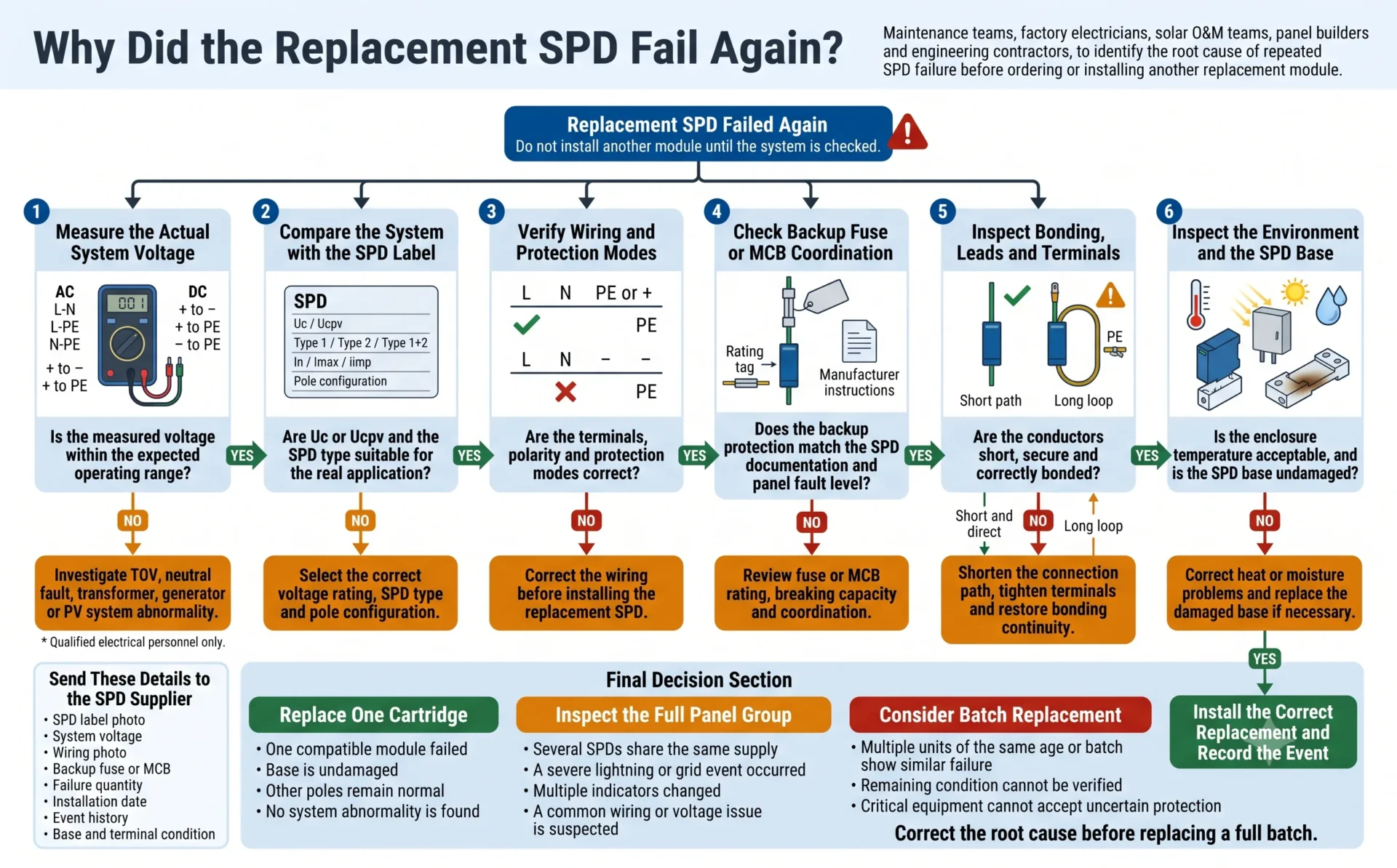
Causas frequentes de falha repetida do SPD
- A peça de reposição possui o mesmo Uc ou Ucpv inadequado do original.
- Uma falha no neutro ou uma tensão anormal do sistema não foi corrigida.
- O cartucho foi substituído, mas a base ou o terminal sofreu dano por aquecimento.
- O fusível de backup ou o MCB continuam selecionados incorretamente.
- A fiação frouxa continua a provocar aquecimento local.
- O invólucro permanece quente demais ou apresenta condensação.
- Um SPD Tipo 2 está exposto a uma aplicação que exige proteção Tipo 1.
- A tensão do arranjo FV excede a suposição original de projeto.
- Apenas um polo foi substituído, embora todos os módulos tenham sido afetados pelo mesmo evento.
- Um cartucho de substituição incompatível foi instalado na base existente.
Não continue substituindo cartuchos sem medir o sistema
Uma segunda falha deve desencadear uma revisão da causa-raiz. Continuar instalando a mesma especificação de SPD sem verificar a tensão de operação, o neutro, o Voc do FV, a fiação, a base e o invólucro pode reproduzir a mesma falha.
12. Quando vários módulos de SPD devem ser verificados ou substituídos?
Um cartucho com falha não significa automaticamente que todos os SPDs da instalação devam ser substituídos. A decisão deve se basear no evento, no histórico de instalação, na exposição comum, na criticidade do sistema e na possibilidade de verificar se a condição de proteção remanescente.
Corrija a causa comum antes de substituir um lote completo
A substituição em lote sem corrigir tensão anormal, Uc ou Ucpv inadequado, fiação incorreta, calor ou umidade pode reproduzir a mesma falha em todos os novos módulos.
Lista de verificação de causas raiz antes de solicitar SPDs de substituição
As informações a seguir ajudam as equipes de manutenção e os fornecedores a distinguir a substituição normal por fim de vida útil de um problema de sistema, seleção, instalação ou possível lote.
Informações do produto
- Modelo completo do SPD e foto legível da etiqueta.
- Type 1, Type 2 ou Type 1+2.
- Uc ou Ucpv.
- In, Imax ou Iimp.
- Up e configuração dos polos.
- Modelo do cartucho plug-in e da base.
- Lote de produção e data de instalação.
Informações do sistema
- Tensão nominal e tensão operacional medida.
- Sistema de aterramento CA ou topologia FV.
- Voc máximo corrigido da string FV.
- Modelo e calibre do fusível de reserva ou do disjuntor magnetotérmico.
- Corrente de curto-circuito prospectiva, se disponível.
- Posição de instalação no sistema de proteção.
- Arranjo do DPS a montante e a jusante.
Evidência de falha
- Estado do indicador e do contacto remoto.
- Fissuras, descoloração ou queimadura.
- Danos térmicos na base ou no terminal.
- Número de unidades com falha.
- Data da falha e condição de operação.
- Raios recentes, interrupção ou evento na rede.
- Se também falhou uma unidade de substituição.
Ambiente de instalação
- Fotos do painel e da fiação.
- Comprimento aproximado do condutor do SPD.
- Arranjo de PE e de equipotencialização.
- Temperatura ambiente e interna do invólucro.
- Exposição direta ao sol, humidade ou condensação.
- Equipamento gerador de calor nas proximidades.
- Tipo de invólucro e grau de proteção IP.
Não tem certeza do porquê de vários SPDs terem falhado?
Envie-nos a etiqueta do SPD, a tensão medida do sistema, a foto da fiação do painel, a proteção de reserva, a quantidade de falhas e a condição de base. A LEEYEE pode ajudar a comparar o modelo com falha com a aplicação real e recomendar uma especificação de substituição adequada para manutenção, montagem de painéis ou encomendas OEM.
Perguntas mais frequentes
Qual é a causa mais comum de falha do SPD?
Não existe uma única causa para todas as instalações. O stress repetido por surtos e a tensão anormal do sistema são causas elétricas comuns. Uc ou Ucpv incorretos, erros de cablagem, proteção de reserva inadequada, temperatura elevada e aplicação incorreta costumam explicar falhas prematuras ou repetidas do SPD.
Falha de SPD é sempre causada por relâmpago?
Não. O raio é apenas uma das possíveis causas. Um neutro desligado, sobretensão temporária, classificação de tensão incorreta, erro de cablagem, sobreaquecimento, humidade, configuração inadequada do sistema ou um possível defeito do produto também podem fazer com que um SPD se desligue ou falhe prematuramente.
Por que um SPD continua falhando após a substituição?
A falha repetida geralmente significa que a causa original permanece. As possíveis causas incluem tensão anormal do sistema, Uc ou Ucpv selecionados demasiado baixos, cablagem incorreta, proteção de reserva inadequada, uma base plug-in danificada, temperatura elevada ou um cartucho de substituição incompatível.
Pulsos de relâmpago repetidos podem desgastar um SPD?
Sim. A corrente de surto repetida cria stress elétrico e térmico nos componentes de proteção. A taxa de degradação depende da energia do evento, da forma de onda, da classificação do SPD, das condições de instalação e do envelhecimento anterior. Não existe um número fixo de eventos de raio que se aplique a todos os SPD.
A alta tensão da rede elétrica pode danificar um SPD?
Sim. Se a tensão permanecer acima da faixa de operação contínua do SPD, o componente limitador de tensão pode conduzir durante demasiado tempo, gerar calor e ativar o seu desconector térmico.
O que acontece se o SPD Uc estiver muito baixo?
A tensão de operação normal ou a variação de tensão esperada pode submeter repetidamente o SPD a esforço. Isso pode aumentar a corrente de fuga, o aquecimento e o envelhecimento do MOV, levando a uma desconexão prematura.
A má ligação à terra pode causar falha no SPD?
Uma ligação equipotencial deficiente, conexões PE frouxas e condutores longos reduzem principalmente o desempenho global de proteção e aumentam a tensão efetiva no equipamento. Podem contribuir para esforço anormal, mas não devem ser considerados uma causa direta automática de falha do SPD.
Um SPD precisa de um fusível ou MCB de backup?
A exigência depende do SPD, do dispositivo de proteção a montante e da instalação. Quando necessário, a proteção de retaguarda elimina a corrente de falha à frequência da rede no ramo do SPD. Sua classificação e capacidade de interrupção devem seguir exatamente a documentação do produto e o nível de falha do painel.
Por que um SPD de CC solar falha repetidamente?
As causas comuns incluem Ucpv abaixo do Voc máximo corrigido do arranjo, uso de um SPD CA no lado CC, topologia fotovoltaica incorreta, modos de proteção inadequados, alta temperatura da caixa combinadora, umidade ou falhas de isolamento e de terra não resolvidas.
Todos os módulos SPD devem ser substituídos quando um módulo falha?
Não automaticamente. Inspecione os polos restantes, a base, os terminais, o histórico de eventos e a condição do sistema. Uma substituição mais abrangente pode ser apropriada após um evento severo comum, falhas repetidas ou quando a condição remanescente não puder ser verificada.
Posso substituir apenas o cartucho SPD plug-in?
Sim, quando o cartucho de reposição for exatamente compatível e a base, os contatos, os terminais e a fiação não estiverem danificados. Substitua ou inspecione mais detalhadamente a unidade completa quando houver fusão, descoloração, fissuras, contatos frouxos ou falha repetida.
Um indicador verde prova que o SPD está instalado corretamente?
Não. Um indicador verde normalmente informa a condição de um componente interno monitorado. Ele não confirma fiação correta, Uc ou Ucpv adequados, proteção de retaguarda correta, condutores curtos ou ligação equipotencial eficaz.
Base Técnica e Notas de Aplicação
A análise de falha do SPD deve se basear na documentação exata do produto, nas medições do sistema e nos requisitos de instalação aplicáveis. As normas a seguir são particularmente relevantes para os tópicos discutidos neste guia:
- IEC 61643-11: requisitos e métodos de ensaio para SPDs conectados a sistemas de energia CA de baixa tensão.
- IEC 61643-31: requisitos e métodos de ensaio para SPDs utilizados em instalações fotovoltaicas.
- IEC 60364-5-53: requisitos de seleção e instalação para dispositivos de seccionamento, manobra, controle e proteção contra surtos em instalações de baixa tensão.
- A Uc ou Ucpv declarada pelo fabricante, o comportamento em TOV, a proteção de retaguarda, as informações de suportabilidade a curto-circuito e as instruções de instalação para o modelo exato de SPD.
As normas e as regras locais de instalação podem ser revisadas. Os engenheiros de projeto devem confirmar a edição e os requisitos regionais aplicáveis à instalação específica.
Nota de segurança: a inspeção do SPD, a medição em tensão energizada e a substituição devem ser realizadas por pessoal elétrico qualificado, utilizando procedimentos apropriados de isolamento, verificação e proteção individual.
