
Selecionando um SPD CC de BESS não é o mesmo que selecionar um SPD de PV solar. O circuito da bateria pode apresentar diferentes condições de corrente de falha, aterramento e de fim de vida. O dispositivo correto deve ser selecionado com base no envelope operacional real da bateria, interface PCS, modos de proteção, corrente de curto-circuito prospectiva e posição de instalação—não apenas pelas palavras “1000 V” ou “1500 V”.
Para selecionar um SPD DC de BESS, primeiro confirme a mais alta tensão contínua da bateria, não apenas a tensão nominal. Em seguida, confirme o arranjo de aterramento DC, modos de proteção necessários, corrente de curto-circuito esperada, proteção de backup, tensão de suportação de impulso do equipamento e se o gabinete da bateria, combinador DC e PCS estão localizados na mesma zona de proteção contra raios.
Para um circuito de bateria não PV, solicite evidências apropriadas para IEC 61643-41:2025 ou outra base de teste de BESS DC aprovada pelo projeto. Um certificado IEC 61643-31 de PV sozinho não comprova a adequação para um circuito DC alimentado por bateria.[1][2]
Conteúdo
- SPD DC BESS vs SPD DC PV
- Qual norma se aplica?
- Passos para seleção do SPD DC BESS
- Como confirmar a tensão máxima
- Modos de aterramento e proteção
- SCCR e proteção de backup
- Tipo 1+2 ou Tipo 2
- Locais do gabinete da bateria e do PCS
- A regra de 10 m é universal?
- Proteção BMS e de comunicação
- Lista de verificação para pedido de SPD CC de BESS
- Transformar dados do projeto em uma especificação SPD
- Três casos típicos de seleção de BESS
- Lista de verificação de evidências do fornecedor
- Erros comuns de especificação
- Perguntas frequentes
Índice
Um SPD CC de BESS não é automaticamente o mesmo que um SPD CC de PV
Ambas as aplicações podem usar equipamentos DC de 1000 V ou 1500 V, mas o rótulo de tensão não descreve o comportamento da fonte durante uma falha de SPD.
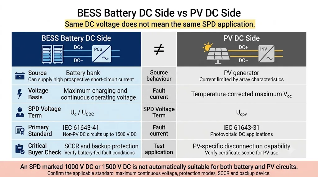
Fonte da bateria BESS
- Pode fornecer alta corrente de curto-circuito prospectiva.
- A tensão varia com o estado de carga, condição da célula e limites de carga.
- Pode usar configurações flutuantes, IT, com polo aterrados ou do meio.
- Requer desconexão segura em condições de falha alimentadas por bateria.
- Está coberto pelo escopo DC não PV da IEC 61643-41:2025.
Fonte do gerador PV
- A corrente é limitada pelas características do array PV.
- A tensão máxima é derivada principalmente da Voc corrigida da string.
- A classificação do produto é comumente exibida como Ucpv.
- Os testes de falha e desconexão específicos de PV se aplicam.
- Coberto pela IEC 61643-31 e selecionado sob diretrizes específicas de PV.
| Item de seleção | Lado da bateria de BESS | Lado do gerador PV | Implicação do comprador |
|---|---|---|---|
| Comportamento da fonte | Fonte de CC alimentada por bateria com potencial alta corrente de falta prospectiva | Fonte de PV limitada pelas características de corrente-tensão do arranjo | Verifique a fonte real utilizada no teste do produto e no estudo de falhas. |
| Base de tensão | Tensão máxima de carregamento e tensão operacional contínua | Voc máximo de string corrigido pela temperatura | Não selecione nenhuma aplicação apenas com base na tensão nominal. |
| Termo de tensão comum | Uc, UCDC ou tensão contínua máxima contínua declarada | Ucpv | Verifique a declaração exata na ficha técnica do fornecedor e no relatório de teste. |
| Norma de aplicação | IEC 61643-41 com IEC 61643-01 | IEC 61643-31 | Um certificado apenas de PV não é uma evidência automática para um circuito alimentado por bateria. |
| Verificação adicional crítica | SCCR, TOV, fusível de backup e desconexão segura | Comportamento de operação e desconexão específico de PV | Peça pela disposição protetora testada, não apenas In ou Imax. |
Qual norma de SPD se aplica a um circuito CC de BESS?
A norma aplicável depende do circuito que está sendo protegido, não apenas se o projeto completo contém baterias ou painéis solares.
| Circuito | Norma de SPD relevante | Exemplos típicos de projetos | Verificação do comprador |
|---|---|---|---|
| Circuito de alimentação DC alimentado por bateria | IEC 61643-41:2025 com IEC 61643-01:2024 | Saída do rack de bateria, gabinete de bateria, combinador DC, entrada DC do PCS | Solicitar evidências de teste BESS/não-PV DC e condições de falha declaradas. |
| Circuito DC fotovoltaico | IEC 61643-31:2018 | String PV, caixa combinadora e entrada DC do inversor PV | Confirmar o escopo do certificado Ucpv e específico de PV. |
| Lado AC do PCS | IEC 61643-11:2025 com IEC 61643-01 | Saída AC do PCS, quadro de distribuição e conexão à rede | Confirmar tensão AC, sistema de aterramento, tipo e modos de proteção. |
| Comunicação e sinalização | IEC 61643-21:2025 | RS485, CAN, Ethernet, alarme, sensor e circuitos de monitoramento | Combinar tensão de sinal, taxa de dados, disposição da linha e tipo de interface. |
Como selecionar um SPD CC de BESS
A sequência de seleção é importante. Começar a partir de Imax ou contagem de polos de produto pode levar a um SPD que possui uma classificação de surto impressionante, mas é incompatível com o circuito real da bateria.
Identificar o ponto exato de proteção DC
Indique se o SPD será instalado em uma saída de suporte de bateria, saída de gabinete de bateria, combinador DC, conversor DC/DC, barramento DC principal ou entrada DC do PCS.
Confirme a tensão contínua máxima
Utilize a tensão de carga máxima permitida da bateria e a faixa operacional real.
Confirme os modos de aterramento e proteção
Determine se o circuito DC é flutuante, IT, aterrado positivo, aterrado negativo, aterrado no ponto médio ou outra configuração.
Verifique a tensão de resistência do equipamento e SPD Up
Inclua a tensão do cabo de conexão, não apenas o Up impresso na folha de dados.
Verifique o SCCR e a proteção de backup
Obtenha a corrente de curto-circuito prospectiva no ponto de instalação.
Selecione Tipo 1, Tipo 1+2 ou Tipo 2 com base no risco
Utilize a avaliação de risco de raios, LPS, limite de LPZ e exposição a cabos.
Confirme a instalação, monitoramento e manutenção
Verifique o comprimento do cabo, a cápsula, o ambiente, a indicação, o contato remoto e o acesso ao serviço.
Não selecione o SPD a partir da tensão nominal do BESS
Um sistema descrito comercialmente como “1000 V BESS” pode operar em uma ampla faixa de tensões.
Verificação básica da tensão máxima
Compare este resultado com a tensão máxima de entrada DC do PCS e os limites operacionais do sistema.
Exemplo
Assuma que uma string de bateria contém 14 módulos em série. A tensão nominal do módulo é de 64 V, mas a tensão de carga máxima permitida é de 72 V.
Tensão de carga máxima: 14 × 72 V = 1008 V DC
| Dados de tensão | Onde obtê-los | Como afeta a seleção do SPD |
|---|---|---|
| Tensão nominal da bateria | Especificação do sistema de baterias | Identifica a classe de tensão, mas não é a entrada final do Uc. |
| Tensão máxima de carga da célula ou módulo | Dados do fabricante da bateria | Usado com a quantidade da série para calcular a tensão máxima da string. |
| Tensão máxima de entrada CC do PCS | Folha de dados e manual do PCS | Confirma a interface do conversor e o limite absoluto de operação. |
| Tensão para a terra por modo de proteção | Diagrama unifilar e estudo de aterramento | Determina a tensão contínua entre +/PE, -/PE e +/- caminhos. |
| TOV ou condição de operação anormal | Estudo de falha do sistema e isolação | Verifica se o SPD pode permanecer estável durante sobretensão não transitória. |
Confirme a disposição de aterramento do BESS CC antes de escolher a contagem de polos
O número correto e a disposição dos componentes de proteção dependem da tensão entre positivo, negativo e terra de proteção em condições normais e de falha.
Sistema DC flutuante ou IT
Nenhum polo está intencionalmente conectado de forma sólida à terra. Revise ambos os caminhos de polo para terra e as condições de falha de terra inicial.
Sistema de polo aterrado
Um polo está intencionalmente referenciado à terra. Os caminhos de proteção necessários diferem de um sistema flutuante.
Ponto médio ou topologia especial
Um ponto médio, barra dividida, estágio DC/DC ou topologia interna do PCS pode alterar a tensão que aparece em cada componente SPD.
| Questão de aterramento | Informações necessárias | Por que muda o SPD |
|---|---|---|
| O barramento da bateria está isolado da terra? | Flutuante, IT ou monitorado através de um dispositivo de monitoramento de isolamento | Altera a tensão normal e a tensão de primeira falha nos caminhos de pólo para terra. |
| Um polo está intencionalmente aterrado? | Aterramento positivo, negativo ou sem aterramento sólido | Altera os modos de proteção necessários e sua tensão contínua. |
| Um ponto médio está aterrado? | Conexão do ponto médio e desequilíbrio permitido | Altera a tensão de estresse do pólo para terra e a disposição dos componentes. |
| O que acontece após a primeira falha de terra? | Alarme, operação contínua ou desligamento imediato | Determina a tensão de estresse temporária no polo saudável. |
| O PCS está galvanicamente isolado? | Arranjo de isolamento do conversor e transformador | Pode alterar o sistema CC efetivo e o caminho de falha. |
SCCR e proteção de backup são verificações obrigatórias do BESS
Um banco de baterias pode fornecer uma corrente de falha substancial. Revise o SPD como parte de uma ramificação protegida completa.
| Parâmetro | O que descreve | O que isso não prova |
|---|---|---|
| Em | Corrente nominal de descarga sob a forma de onda de impulso especificada | Interrupção segura de uma falta de alta frequência de potência alimentada pela bateria. |
| Imax | Valor máximo de ensaio da corrente de descarga do Tipo 2 | Adequação para todos os níveis de exposição do BESS ou sistemas de aterramento. |
| Iimp | Capacidade de corrente de impulso de raio do Tipo 1 | Uc, Up, SCCR ou coordenação adequada do fusível de retaguarda. |
| Para cima | Nível de proteção de tensão durante o ensaio de surto declarado | A tensão final no PCS após a indutância dos cabos de ligação. |
| SCCR / Isccr | Desempenho de curto-circuito declarado em condições especificadas | Adequação quando a corrente de falta do projeto ou o fusível de backup diferem. |
O lado CC do BESS deve usar SPD Tipo 1+2 ou Tipo 2?
A resposta depende do conceito de proteção contra descargas atmosféricas e da transição da ZPL.
Avaliar Tipo 1 ou Tipo 1+2 quando
- Pode entrar corrente parcial de raio no circuito CC.
- A linha cruza a partir de uma zona de proteção exposta.
- Há um SPDA externo e a separação não pode ser mantida.
- A avaliação de risco do projeto exige capacidade de corrente de raio.
Tipo 2 pode ser apropriado quando
- O circuito está dentro de uma ZPL protegida.
- Apenas surtos induzidos e de manobra são esperados.
- O cabo é roteado dentro de uma área adequadamente protegida.
- A especificação do projeto suporta Tipo 2.
Onde o SPD deve ser instalado entre o gabinete da bateria e o PCS?
Proteja o terminal do equipamento e a fronteira da zona por onde o surto entra.
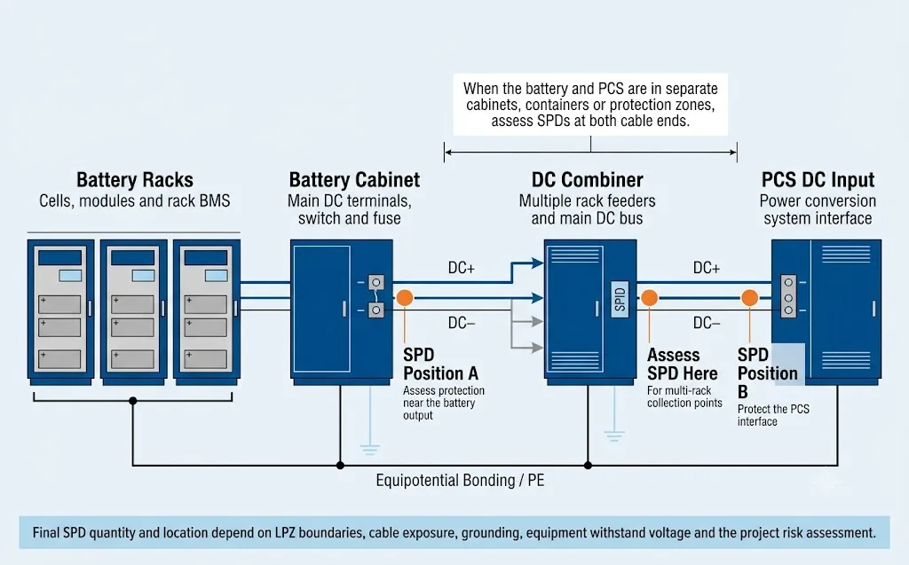
Mapa simplificado de seleção. Isto não é um diagrama de fiação e não substitui o diagrama unifilar do projeto.
| Disposição do sistema | Locais possíveis para o DPS | Verificações importantes |
|---|---|---|
| Bateria e PCS em um gabinete integrado | Próximo ao PCS protegido ou ao ponto de distribuição de CC designado | Layout interno, comprimento dos cabos e resistência do gabinete. |
| Bateria e PCS em gabinetes adjacentes | Saída da bateria, entrada do PCS ou ambos após revisão de coordenação | Rota de cabos, coordenação de aterramento comum e equipamentos Up/Uw. |
| Bateria e PCS em contêineres separados | Normalmente, avalie ambas as extremidades do cabo CC de interconexão | SPDA, rota subterrânea ou exposta, blindagem e aterramento. |
| Múltiplos racks através do combinador CC | Alimentador de rack, barramento principal do combinador e/ou entrada do PCS | Contribuição de corrente em paralelo e coordenação de DPS. |
Todo BESS precisa de SPDs em ambas as extremidades quando o cabo ultrapassa 10 m?
Nenhuma regra universal de BESS deve ser reduzida apenas ao comprimento do cabo. A distância comumente citada só é significativa quando considerada em conjunto com a zona de proteção, o trajeto do cabo, o arranjo de equipotencialização e o nível de suportabilidade do equipamento remoto.
A orientação de aplicação pode permitir um DPS em um arranjo específico onde a bateria e o PCS compartilham um sistema de aterramento equipotencializado e o cabo de interconexão permanece dentro de um trajeto adequadamente protegido. Esse exemplo condicional não deve ser convertido em uma regra universal para todos os contêineres BESS e cabos externos.[8]
| Questão de decisão | Por que isso importa |
|---|---|
| O cabo atravessa uma fronteira de LPZ? | Determina onde a corrente de surto pode entrar e onde um DPS deve ser coordenado. |
| O cabo está acima do solo, subterrâneo ou em conduíte metálico? | Altera a exposição ao acoplamento eletromagnético de raios. |
| Ambas as estruturas compartilham um sistema de aterramento equipotencial comum? | Diferenças de potencial podem conduzir correntes de surto através da conexão CC. |
| Qual é o Uw dos terminais do PCS e da bateria? | Determina se a tensão residual na extremidade remota permanece aceitável. |
| Ambos os DPS podem ser instalados com cabos curtos? | Cabos longos adicionam tensão indutiva e podem comprometer um nível de proteção de tensão (Up) que, de outra forma, seria adequado. |
Um SPD de energia CC não protege as linhas de comunicação do BMS
A disponibilidade do BESS depende da comunicação entre racks de bateria, BMS, PCS, EMS, sistemas de incêndio e equipamentos de monitoramento remoto.
Lista de verificação para pedido de SPD CC de BESS
“1500 V, 40 kA, 2P” não é suficiente para uma recomendação responsável de BESS.
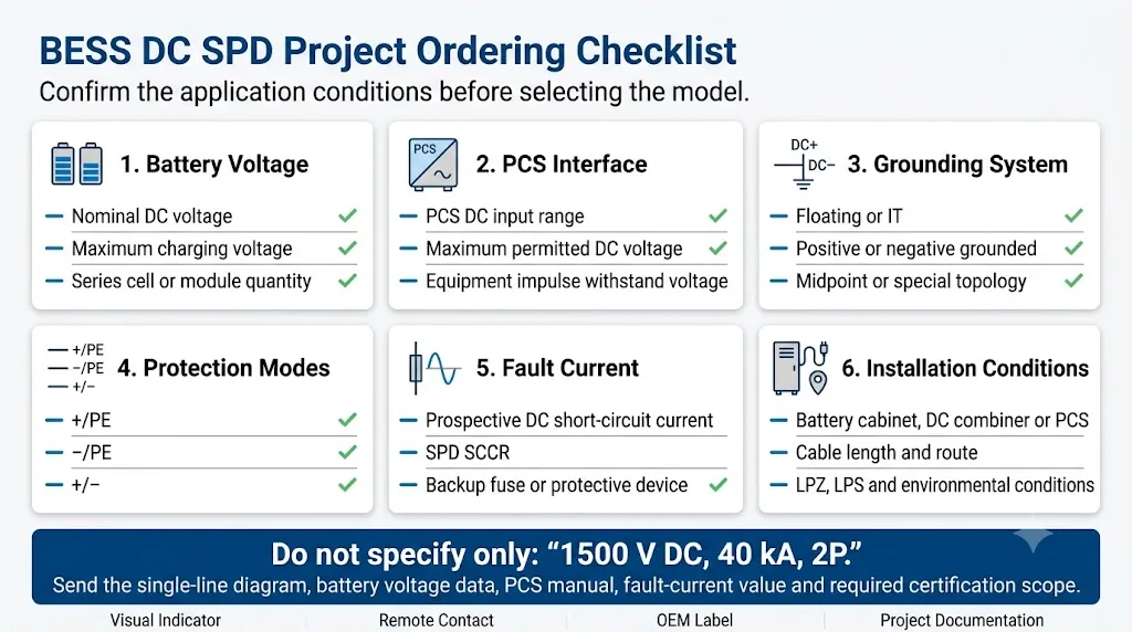
| Parâmetro | Informações a fornecer | Por que o fornecedor precisa disso |
|---|---|---|
| Ponto de aplicação | Rack de baterias, gabinete, combinador, barramento CC, conversor CC/CC ou entrada de PCS | Define a fonte e o equipamento protegido. |
| Tensão nominal em CC | Tensão nominal do sistema de baterias | Identifica a classe de tensão geral. |
| Tensão máxima de carregamento | Tensão contínua máxima permitida da bateria | Entrada principal para seleção de Uc ou UCDC. |
| Configuração da bateria | Tipo de célula/módulo e quantidade em série/paralelo | Permite a verificação da faixa de operação. |
| Faixa de entrada CC do PCS | Tensão de entrada CC mínima, nominal e máxima | Confirma a compatibilidade da interface. |
| Sistema de aterramento CC | Flutuante, IT, aterramento positivo, aterramento negativo ou aterramento no ponto médio | Determina os modos de proteção e a tensão de estresse. |
| Corrente de falta prospectiva | Corrente de curto-circuito CC calculada no ponto do DPS | Necessário para verificação de SCCR e dispositivo de backup. |
| Proteção de derivação existente | Tipo de fusível ou disjuntor, tensão, corrente e capacidade de interrupção | Verifica a coordenação com as instruções do DPS. |
| Uw do equipamento | Tensão suportável de impulso dos terminais da bateria, BMS, combinador e PCS | Verifica se o nível de proteção instalado é adequado. |
| Distância e percurso do cabo | Comprimento, percurso aéreo/subterrâneo, blindagem e contenção | Suporta decisões de posicionamento e coordenação. |
| Condições ambientais | Temperatura, altitude, umidade, salinidade, vibração e grau de poluição | Afeta o isolamento, a redução de potência (derating) e o projeto do invólucro. |
| Requisitos do OEM | Logotipo, etiqueta, número da peça, embalagem e documentação | Permite uma revisão comercial e de produção precisa. |
Transforme os dados do projeto do BESS em uma especificação final de SPD
Os dados da consulta devem conduzir a um resultado técnico definido. Sem essa conversão, o comprador recebe uma lista de perguntas, mas ainda não consegue comparar os fornecedores com base nos mesmos critérios.
| Entrada do projeto | Decisão de engenharia | Campo de especificação final do DPS |
|---|---|---|
| Tensão máxima de carregamento e tensão em relação à terra | Selecione uma classificação de tensão contínua que permaneça estável em todos os modos necessários | Uc / UCDC por modo de proteção |
| Topologia flutuante, de polo aterrado ou de ponto médio | Defina os caminhos que requerem limitação de surto | +/PE, −/PE, +/− e disposição do módulo |
| Tensão suportável de impulso da bateria, PCS e combinador | Defina a tensão residual instalada máxima aceitável | Para cima por modo de proteção, além do requisito de comprimento do cabo |
| LPS, LPZ e exposição de cabos | Determinar a classe de surto e o regime de energia esperados | Tipo 1, Tipo 1+2 ou Tipo 2; Iimp, In e Imax |
| Corrente de curto-circuito prospectiva da bateria | Verificar a desconexão segura sob a condição real da fonte | SCCR / Isccr e fusível de reserva aprovado |
| Layout da bateria para o PCS e rota dos cabos | Decidir se uma ou ambas as extremidades do cabo requerem proteção coordenada | Ponto de instalação A, ponto B ou disposição coordenada de dois estágios |
| Requisitos de manutenção e monitoramento | Definir funções de serviço e status remoto | Módulo plugável, indicador visual e contato remoto |
| Mercado de projeto e lista de aprovação | Confirmar o escopo aceitável de testes e documentação | Evidências, relatórios e declarações IEC/EN/UL aplicáveis |
Folha de especificações finais mínima
Utilize os campos a seguir ao comparar cotações. O fornecedor não deve substituir nenhum item ausente por um folheto de produto genérico.
Três casos típicos de seleção de SPD CC de BESS
Estes exemplos demonstram o caminho de decisão em vez de prescrever um modelo universal. Os valores finais devem ser obtidos da bateria real, do PCS e da documentação do projeto.
Gabinete integrado de bateria e PCS
- Condição do projeto
- A bateria e o PCS compartilham um gabinete único com condutores CC internos curtos.
- Análise principal
- Tensão máxima da bateria, topologia de aterramento, PCS Uw, comprimento do condutor interno e corrente de falha.
- Caminho de decisão provável
- Avalie uma posição coordenada de DPS próxima à interface de distribuição PCS/CC protegida, sujeita ao projeto do gabinete.
Contêiner de bateria separado do PCS
- Condição do projeto
- O cabo CC externo conecta dois gabinetes ou contêineres e pode cruzar um limite de LPZ.
- Análise principal
- SPDA, rota de cabos, equipotencialização comum, equipamento remoto Uw, exposição do condutor e localizações de ambos os terminais.
- Caminho de decisão provável
- Avalie a proteção coordenada tanto na saída da bateria quanto na entrada do PCS, em vez de considerar apenas o comprimento do cabo.
Múltiplos racks de bateria através de um combinador CC
- Condição do projeto
- Vários alimentadores de rack paralelos entram em um combinador CC comum antes do PCS.
- Análise principal
- Contribuição de corrente de falta paralela, proteção do alimentador, SCCR do barramento principal, localização do combinador e coordenação do PCS.
- Caminho de decisão provável
- Avalie a proteção do ramal, do combinador e do PCS como um sistema coordenado; não selecione o DPS apenas pelo Imax.
Que evidências um fornecedor de SPD CC de BESS deve fornecer?
Uma declaração do fornecedor como “adequado para BESS de 1500 V” não é suficiente por si só. O comprador deve verificar o escopo e as condições subjacentes à alegação.
- Norma de teste aplicávelEscopo do relatório ou certificado que identifica a base da aplicação não fotovoltaica (CC) ou de BESS.
- Uc / UCDC declaradoClassificação de tensão contínua para cada modo de proteção necessário, não apenas a tensão total do sistema.
- Modo de proteção acimaNível de proteção de tensão para o arranjo real +/PE, −/PE e/ou +/−.
- Condições de SCCR / IsccrClassificação de curto-circuito declarada e o dispositivo de proteção de reserva testado ou aprovado.
- Instruções do fusível de reservaClasse do fusível, tensão nominal, corrente, capacidade de interrupção e valor máximo permitido.
- Diagrama de conexãoCabeamento correto para o sistema de aterramento do projeto e disposição dos módulos.
- Classificações ambientaisTemperatura, altitude, invólucro, poluição, vibração e outros limites relevantes.
- Consistência de produçãoRastreabilidade, controle de componentes recebidos, inspeção de rotina e processo de controle de mudanças.
- Informações de monitoramentoEstado do indicador, classificação de contato remoto e instruções de substituição ou manutenção.
- Consistência documentalA etiqueta do produto, a ficha técnica, o relatório de teste, a cotação e a embalagem devem descrever o mesmo modelo.
Erros comuns na especificação do SPD CC de BESS
Perguntas frequentes sobre a seleção de SPD CC de BESS
Um SPD DC de PV pode ser usado no lado da bateria de um BESS?
Não automaticamente. O fornecedor deve apresentar evidências de que o produto é adequado para a tensão do circuito da bateria, a fonte, a corrente de curto-circuito e os modos de proteção.
Uma especificação de BESS deve usar Uc ou Ucpv?
Ucpv é a designação específica para FV. Para um circuito de bateria BESS não fotovoltaico, utilize a classificação contínua máxima de CC declarada pelo fabricante, comumente indicada como Uc ou UCDC.
Posso selecionar um SPD de 1000 V para um BESS nominal de 1000 V?
Não apenas a partir da tensão nominal. Calcule a tensão máxima de carregamento da bateria e confirme a tensão contínua em cada modo de proteção.
Um SPD deve ser instalado tanto na bateria quanto no PCS?
Ambas as extremidades devem ser avaliadas quando a bateria e o PCS estiverem em gabinetes, contêineres, edifícios ou zonas de proteção separados.
As linhas de comunicação do BMS precisam de proteção contra surtos separada?
Sim, quando a avaliação de risco identificar exposição. Um DPS de potência CC não protege interfaces RS485, CAN, Ethernet, sensores ou de controle.
Um Uc mais alto pode sempre ser utilizado para maior segurança?
Não. Uma classificação de tensão contínua mais elevada pode reduzir operações indesejadas, mas também pode aumentar o Up. O DPS selecionado deve permanecer estável na tensão máxima de operação, garantindo simultaneamente a proteção do PCS e do isolamento da bateria.
O SCCR é o mesmo que Imax?
Não. Imax é um parâmetro de corrente de descarga de impulso. O SCCR ou Isccr refere-se ao comportamento declarado do produto sob uma condição de curto-circuito da fonte de alimentação e, normalmente, depende de um dispositivo de proteção de retaguarda aprovado.
Quais documentos devem ser anexados a uma consulta sobre SPD DC BESS?
Anexe o diagrama unifilar, os dados de tensão máxima da bateria, o manual do PCS, as informações de aterramento, o valor da corrente de falta prospectiva, o layout do gabinete, o trajeto dos cabos, as normas exigidas e os requisitos de documentação do fabricante (OEM).
Solicitar uma revisão da aplicação do SPD CC de BESS
Envie as condições do projeto para que a tensão, os modos de proteção, a corrente de falta, a proteção de retaguarda e a posição de instalação possam ser analisados antes da recomendação de um modelo.
- Tensão máxima da bateria
- Faixa de entrada CC do PCS
- Topologia de aterramento CC
- Corrente de falta prospectiva
- Diagrama unifilar
- Layout do gabinete e cabeamento
- Norma de DPS exigida
- Necessidades de OEM e documentação
Referências
- Comissão Eletrotécnica Internacional, IEC 61643-41:2025 — Dispositivos de proteção contra surtos conectados a sistemas de energia CC de baixa tensão .
- Comissão Eletrotécnica Internacional, IEC 61643-31:2018 — Requisitos e métodos de ensaio para DPS para instalações fotovoltaicas .
- Comissão Eletrotécnica Internacional, IEC 61643-01:2024 — Requisitos gerais e métodos de ensaio para DPS de baixa tensão .
- Comissão Eletrotécnica Internacional, IEC 62305-2:2024 — Proteção contra descargas atmosféricas, gerenciamento de risco .
- Comissão Eletrotécnica Internacional, IEC 62305-4:2024 — Sistemas elétricos e eletrônicos em estruturas .
- Comissão Eletrotécnica Internacional, IEC 61643-21:2025 — DPS conectados a redes de telecomunicações e sinalização .
- ABB Furse, Proteção de Sistemas de Armazenamento de Energia em Baterias — Série ESP BESS de DPS para Linhas de Energia CC .
- Raycap, Proteção contra surtos e sobretensões em sistemas de armazenamento de energia por bateria .
- Mersen, Soluções de proteção para sistemas de armazenamento de energia por bateria .
