
A wind turbine combines an exposed rotor, a conductive tower, long internal cables, high-power conversion equipment and sensitive control electronics. Effective wind turbine surge protection must therefore cover more than the main power entrance.
The protection architecture should follow the real electrical boundaries between the hub, nacelle, generator, converter, tower cable route, tower-base cabinet, transformer interface and wind-farm communication network. Each circuit must be assessed according to its voltage, waveform, grounding arrangement, surge exposure and connected equipment.
Índice
Resposta Rápida
A utility-scale wind turbine may require several coordinated SPDs because its power, converter, control and communication circuits cross different protection boundaries. Lightning-current-capable protection may be required where conductors can carry partial lightning current. Downstream Type 2 protection may then reduce residual or induced surges near power and control equipment.
Low-voltage DC, sensor and communication circuits require interface-specific protection. An AC power SPD cannot replace a DC control SPD or a data-line SPD.
IEC 61400-24 covers protection of wind turbine blades, structural components, electrical systems and control systems against direct and indirect lightning effects. The complete turbine protection concept must be assessed and verified rather than treating one SPD as an isolated solution.[1]
Buyer meaning: identify every protected circuit and installation boundary before selecting an SPD. Turbine megawatt rating alone does not define the required model.
The hub, nacelle, converter, tower base and SCADA network can have different surge duties.
AC power, DC control and communication interfaces require different protection technologies.
PWM waveforms and nonlinear sources can differ significantly from normal utility power.
Bonding, conductor routing, connection length and SPD coordination influence equipment-terminal voltage.
Why Wind Turbines Need Layered Surge Protection
Wind turbines are exposed to several transient sources. A direct lightning strike can affect the rotor, nacelle or tower. Lightning current flowing through the structure can create potential differences between equipment locations. Electromagnetic coupling can also induce surges in long internal cables.
Internal switching is another source of stress. Contactors, motors, transformers, generators and converters can generate transient overvoltages during normal operation or electrical faults.
These effects do not enter every circuit in the same way. Main power conductors may carry high surge energy, while a PLC input, encoder or communication port can fail at a much lower residual voltage.
SPDs protect electrical and electronic circuits. They do not replace blade receptors, structural lightning-current paths, tower bonding, the foundation earth system or the complete external lightning protection design.
The turbine contains several protection environments
A practical engineering review divides the turbine into physical and electrical areas:
- Rotor blades and blade lightning-current paths;
- Hub and pitch-control equipment;
- Nacelle power, generator and control systems;
- Machine-side and grid-side converter circuits;
- Long vertical power and communication cables;
- Tower-base switchgear and control cabinets;
- Transformer and collection-grid connections;
- SCADA, condition monitoring and wind-farm communications.
The protection level at each area should be based on the turbine lightning protection concept, expected current sharing, equipment immunity and conductive paths crossing the area boundary.[1][8]
Wind Turbine Surge Protection Architecture
Start with the turbine single-line diagram and cable schedule. Mark every power, control and communication circuit that crosses between exposed equipment and protected enclosures.
Where conductors may carry partial lightning current across a protection boundary, the selected SPD must have suitable lightning-current discharge capability. At downstream boundaries, another protection stage may be needed to reduce residual or induced voltage to a level compatible with the connected equipment.[3][4]
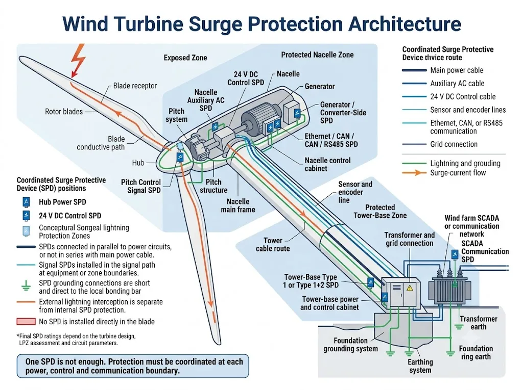
The following table shows the main protection questions at each turbine location.
| Localização | Typical circuits | Main surge concern | Engineering decision |
|---|---|---|---|
| Hub | Pitch power, backup supply, controller, encoder and bus lines | Close proximity to blade lightning-current paths | Protect each power and signal interface at the relevant boundary |
| Nacelle | Generator, auxiliary AC, PLC, yaw, cooling and weather equipment | Induced surges, equipment switching and cable entries | Coordinate nacelle distribution and equipment-level protection |
| Converter section | Machine side, DC link, grid side, feedback and control | Non-standard waveforms and semiconductor sensitivity | Confirm source type, waveform, grounding and fault conditions |
| Tower cable route | Main power, auxiliary supply, control and copper data | Long cable exposure and electromagnetic coupling | Review cable separation, shielding, bonding and both terminations |
| Tower base | Switchgear, controller, UPS and transformer interface | Protection boundary and incoming or outgoing surge energy | Evaluate Type 1, Type 1+2 or Type 2 duty from the actual current path |
| Wind-farm network | SCADA, Ethernet, RS485, alarms and monitoring | Potential differences transferred through copper lines | Match signal protection to protocol, bandwidth and wiring mode |
Procurement conclusion: physical location helps identify the risk, but the actual circuit conditions determine the SPD model.
Protection by Turbine Location
Blade receptors and internal conductive paths are part of the external lightning protection system. The design must carry lightning current toward the hub and structural current path without damaging blade materials or internal equipment.[1]
An SPD is not a substitute for the blade lightning-current path. SPDs protect the electrical circuits connected to equipment in or near the hub.
Pitch equipment may include drives, motors, batteries or capacitors, chargers, encoders, controllers and communication buses. These devices can operate at different AC, DC and signal levels.
Separate the motor power, controller supply, backup supply, encoder and communication interfaces before selecting protection.
The nacelle can contain the generator, converter, yaw system, lubrication equipment, cooling system, hydraulics, auxiliary distribution and the main turbine controller.
One nacelle AC SPD does not automatically protect every downstream DC supply, sensor input or data interface.
Long vertical cables can be exposed to induced voltage and potential differences between the nacelle and tower base. Cable routing, shield termination, bonding and separation from major lightning-current paths should be reviewed together.
The tower base commonly contains switchgear, the turbine controller, auxiliary distribution, a UPS, converter equipment or transformer connections. The exact arrangement varies by turbine platform.
Protection must follow the actual circuit boundary. Do not assume that every tower base requires the same Type 1 SPD configuration.
The transformer may be installed in the nacelle, tower or an external equipment area. Its position changes the low-voltage and medium-voltage protection interfaces.
Low-voltage SPDs and medium-voltage surge arresters are different product categories. The complete transformer and collection-system design requires project-specific engineering.
Main Power and Tower-Base SPD Selection
IEC 61643-11:2025 applies to SPDs connected to AC circuits and equipment rated up to 1,000 V RMS. It defines performance and safety requirements for devices intended to limit surge voltage and divert surge current.[3]
The required device cannot be selected from the turbine megawatt rating. The buyer must confirm the electrical conditions at the exact installation point.
Parameters to confirm for the main power circuit
- Nominal system voltage;
- Maximum continuous operating voltage;
- Voltage between live conductors and earth;
- Frequency and waveform;
- Earthing arrangement;
- Expected surge or partial lightning-current duty;
- Required voltage protection level;
- Equipment impulse withstand level;
- Prospective short-circuit current;
- SPD short-circuit withstand capability;
- Permitted backup fuse or circuit breaker;
- Temporary overvoltage conditions;
- Remote status contact requirement.
The SPD must match the real conductor-to-conductor and conductor-to-earth voltage. Using an unsuitable Uc can cause premature stress, unstable operation or an unnecessarily high protection level.
Uc must match the real operating condition
Uc is the maximum continuous operating voltage declared for the SPD. It must remain suitable during the expected normal operating condition of the circuit.
A higher Uc can provide more operating-voltage margin, but it does not automatically mean better protection. The achievable Up may also be higher, reducing the protection margin for downstream equipment.
Temporary overvoltage and neutral or grounding faults must also be considered. The detailed relationship between Uc, TOV and premature SPD failure is explained in the SPD TOV Withstand Guide.
Short-circuit conditions are part of SPD selection
Prospective short-circuit current can differ substantially between a low-power auxiliary circuit, a converter-fed circuit and a grid-connected switchboard. The SPD, its internal disconnector and any specified external backup protection must be suitable for that exact location.
IEC 61643-12 provides selection, location and coordination principles for SPDs connected to low-voltage AC systems.[4] The product manufacturer’s maximum backup-protection data must also be checked. For a detailed procurement workflow, see the SPD Backup Fuse and MCB Selection Guide.
Generator and Converter Surge Protection
The generator and converter section is where a wind turbine differs most clearly from a normal distribution board. Depending on the turbine topology, protection may need to be assessed at the generator stator, DFIG rotor, machine-side converter, DC section, grid-side converter and transformer interface.
IEC 61643-11 states that its AC test requirements assume a source with a linear voltage-current characteristic and preferred frequencies of 50/60 Hz. When an SPD is connected to a different source type or frequency, expected system and fault conditions require careful consideration.[3]
This is especially important for PWM converter outputs, variable-frequency machine-side circuits and other nonlinear sources.
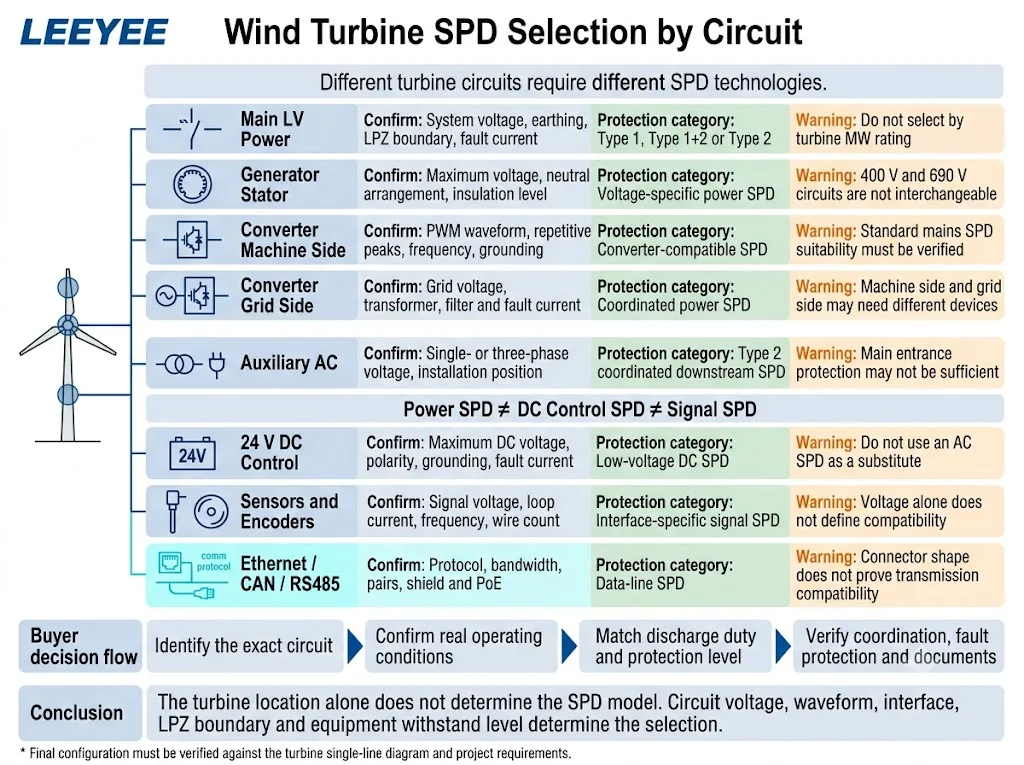
Each electrical side of the generator and converter system must be identified separately.
| Circuito | Informações necessárias | Por que isso importa |
|---|---|---|
| Generator stator | Rated voltage, maximum voltage, neutral arrangement and insulation level | Voltage to earth and equipment withstand determine Uc and Up requirements |
| DFIG rotor | Rotor voltage range, operating mode and converter limits | The rotor circuit is not equivalent to a utility-fed AC circuit |
| Machine-side converter | PWM waveform, repetitive peaks, switching frequency and grounding | Non-sinusoidal stress can affect SPD operating stability and heating |
| Grid-side converter | Grid voltage, filter, transformer and fault-current condition | System behaviour differs before and after the converter or transformer |
| DC circuit | Maximum DC voltage, polarity, grounding and fault current | DC interruption and fault behaviour differ from AC applications |
| Control and feedback | Interface voltage, signal type, bandwidth and reference potential | A power SPD cannot provide suitable signal protection |
Procurement conclusion: machine-side and grid-side circuits may require different devices even when they belong to the same converter assembly.
DC circuits require DC-rated protection
IEC 61643-41:2025 applies to SPDs connected to DC circuits and equipment rated up to 1,500 V DC. It also requires careful consideration when the source is nonlinear or has different fault characteristics from the assumed test source.[7]
A DC-rated label alone is not enough. Confirm maximum continuous DC voltage, polarity, earthing, available fault current and the source’s ability to sustain a DC arc.
The turbine designer or converter manufacturer should confirm acceptable SPD technology, capacitance, leakage current, clamping behaviour and installation position for converter-side applications. A standard mains SPD must not be assumed suitable from voltage rating alone.
Up must be evaluated at the equipment terminals
The declared SPD voltage protection level is not always the final voltage appearing at the converter or controller terminals. Connection inductance, cable length, routing and oscillation can add voltage to the protected circuit.
Keep connections short and direct. The IEC 60364-5-534 SPD Installation Guide explains how connection length and conductor routing affect practical protection.
If the distance or equipment immunity requires another protection stage, verify coordination between upstream and downstream devices instead of adding an untested combination.
Engineers evaluating converter interfaces may also use the PCS Inverter Surge Protection Guide as a related reference for separating AC, DC, control and communication boundaries. Final wind-turbine decisions must still follow the turbine and converter documents.
Nacelle Auxiliary Power and Control Cabinets
Nacelle systems can share the same physical enclosure while operating at different electrical levels. Typical circuits include three-phase auxiliary power, single-phase service supply, 24 V DC control, yaw drives, cooling, lubrication, hydraulics, heaters and aviation warning equipment.
The incoming nacelle AC SPD protects only the circuit to which it is connected. It does not automatically protect a remote 24 V sensor, controller input or Ethernet port.
Divide the nacelle by real electrical interfaces
- Three-phase auxiliary AC distribution;
- Single-phase service and control supply;
- Low-voltage DC control supply;
- Motor and drive circuits;
- External weather-equipment power;
- Controller input and output lines;
- Communication and remote-alarm lines.
One cabinet may require multiple SPD technologies. The correct number of devices follows the number of exposed electrical interfaces, not the number of enclosures.
External nacelle equipment needs separate review
Anemometers, wind vanes, aviation lights and other equipment mounted outside the main nacelle enclosure can be exposed to a different electromagnetic environment.
Review both the equipment power conductors and its data or measurement conductors. Their cable-entry point can form a separate protection boundary even when both cables terminate in the same cabinet.
Hub and Pitch-System Protection
The pitch system may include motors, drives, controllers, backup batteries or capacitors, chargers, encoders and communication interfaces. These circuits are located close to the blade and hub lightning-current path.
A complete pitch-system review should separate at least five interfaces:
- Pitch motor power: confirm AC or DC voltage and drive topology;
- Controller supply: confirm voltage range and grounding arrangement;
- Backup supply: confirm battery or capacitor voltage and fault behaviour;
- Encoder and feedback: confirm signal type, frequency and conductor count;
- Communication bus: confirm CAN, Ethernet or another protocol.
One generic “hub SPD” is unlikely to match all these interfaces. The hub wiring diagram and pitch-system documentation should be provided before quotation.
Ask the turbine or pitch-system supplier for the maximum operating voltage and interface data, not only the nominal controller voltage.
Sensor, Communication and SCADA Protection
A turbine can remain mechanically intact after a lightning event but stop producing because a sensor input, controller port or communication interface has failed.
IEC 61643-21:2025 covers SPDs connected to telecommunications and signalling networks rated up to 1,000 V RMS or 1,500 V DC. Its scope also includes networks that carry power and data on the same line, such as Power over Ethernet.[5]
IEC 61643-22 provides selection, location and coordination principles for signal-line SPDs.[6]
For signal protection, transmission performance can be as important as nominal voltage.
| Interface | Parâmetros a confirmar | Common procurement error |
|---|---|---|
| 4–20 mA | Loop voltage, current, wire count and grounding mode | Selecting only by a 24 V label without checking loop resistance |
| RS485 | Working voltage, pairs, data rate, reference and shield | Ignoring capacitance and transmission performance |
| CAN bus | CAN type, bus voltage, speed and conductor arrangement | Treating CAN and RS485 as identical interfaces |
| Ethernet Industrial | Category, bandwidth, shield, connector and PoE | Matching the RJ45 connector but not network performance |
| Encoder | Supply, output type, frequency and conductor count | Using a general signal SPD that distorts the pulse output |
| Weather station | Sensor supply, heater supply, analogue output and data interface | Protecting data but ignoring power and heater conductors |
Procurement conclusion: connector shape and nominal voltage do not prove compatibility with a data or sensor interface.
When protection may be needed at both cable ends
A long copper cable can transfer a surge or potential difference between two equipment locations. Depending on the protection-zone arrangement, bonding system and interface design, protection may be required at both terminations.
The two SPDs must be compatible with the same protocol and earthing concept. Installing unrelated devices at both ends can increase capacitance, reduce signal quality or create an unsuitable bonding path.
O Remote I/O Surge Protection Guide provides additional selection logic for 24 V DC, DI, DO, AI, AO and RS485 interfaces exposed through long field cables.
Fibre reduces one path but does not remove every risk
The optical fibre itself does not conduct a conventional electrical surge. However, the complete cable may contain metallic armour, strength members or tracing conductors. Media converters and their power supplies can also remain exposed.
Confirm the complete cable construction rather than assuming every fibre link provides total galvanic isolation. For copper Ethernet and PoE interfaces, also verify category, data rate, pairs and shielding as explained in the Guia de Seleção de Protetores de Surto RJ45.
Tower Grounding, Bonding and Cable Installation
An SPD cannot control surge voltage without a suitable path for diverted current. The design must limit potential differences between the tower structure, nacelle frame, equipment cabinets, cable shields, PE conductors and local equipotential bonding bars.
IEC 62305-4 covers the design, installation, inspection, maintenance and testing of surge protection measures for electrical and electronic systems exposed to lightning electromagnetic impulse.[8]
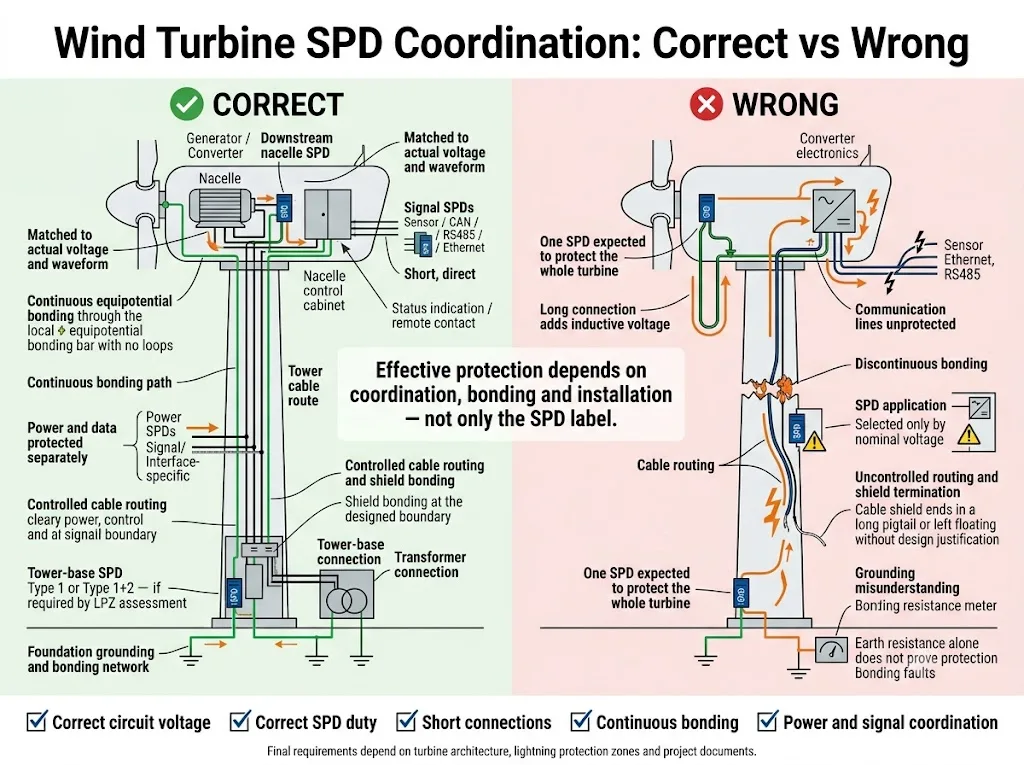
Review the complete surge-current path
- Blade and hub conductive path;
- Nacelle frame and machinery bonding;
- Tower-section electrical continuity;
- Foundation and wind-farm earthing network;
- Control-cabinet and switchgear bonding bars;
- SPD connection to the local bonding point;
- Cable-shield termination at the designed boundary;
- Transformer and collection-system bonding.
Low-frequency earth resistance is only one part of the design. Lightning-current distribution, conductor geometry, bonding continuity, soil conditions, foundation construction, touch and step voltage and high-frequency impedance also require evaluation.
Keep SPD connections short and direct
During a fast surge, connecting-conductor inductance can create additional voltage. Long loops or remote PE connections can therefore increase the voltage at the protected equipment.
Position the SPD close to the cable entry or protected boundary. Follow the manufacturer’s connection arrangement and avoid unnecessary conductor length and loops.
Shield termination must follow the EMC design
Cable shields can reduce electromagnetic coupling when selected and terminated correctly. The suitable termination method depends on the protocol, EMC requirement, bonding network and turbine design.
Do not apply a universal rule that every shield must always be bonded at one end or always at both ends. The project designer must confirm the required method.
How Type 1 and Type 2 SPDs Are Coordinated
SPD coordination means that each protection stage operates within its capability and reduces the remaining stress for the next stage and the protected equipment.
A Type 1 or Type 1+2 SPD may be required where conductors can carry partial lightning current. A Type 2 SPD is generally used for downstream protection against residual or induced surges. The final arrangement must follow the lightning protection concept and actual circuit conditions.[3][4]
Determine whether the circuit may carry partial lightning current, induced surge current or only residual transient energy.
Check conductor-to-conductor and conductor-to-earth voltage, waveform, fluctuation and temporary overvoltage.
Use the turbine risk assessment and current-sharing concept instead of applying one generic Iimp or In value.
Compare the coordinated protection level, including installation effects, with the equipment impulse withstand level.
Use combinations supported by manufacturer coordination data or obtain project-level verification where required.
Confirm prospective short-circuit current, SPD fault behaviour and the permitted external backup fuse or circuit breaker.
For a deeper explanation of protection levels, separation distance and energy coordination, see the Type 1, Type 2 and Type 3 SPD Coordination Guide.
When is Type 3 protection relevant?
Type 3 protection may be useful close to sensitive equipment when the upstream system and installation conditions cannot reduce the remaining surge voltage sufficiently.
It is not automatically required at every PLC or controller. Confirm equipment immunity, cable distance, upstream protection and coordination data for the selected devices.
Type 1, Type 2 and Type 3 describe protection duties and test classifications. They do not create a universal rule that every wind turbine must use one fixed type at the tower base, nacelle and equipment terminals.
Wind Turbine SPD Selection Matrix
Use this matrix as an enquiry guide, not as a substitute for the turbine electrical design.
| Ponto de proteção | Circuito Típico | Initial SPD direction | Project confirmation |
|---|---|---|---|
| Tower-base entrance | Main low-voltage supply | Evaluate Type 1, Type 1+2 or Type 2 | LPZ boundary, system voltage, current sharing and fault current |
| Nacelle cabinet | Auxiliary AC distribution | Coordinated downstream Type 2 | Upstream protection, cable route and equipment withstand |
| Generator | Stator or rotor circuit | Voltage- and topology-specific protection | Maximum voltage, waveform, insulation and neutral arrangement |
| Converter | Machine side, DC or grid side | Converter-compatible AC or DC SPD | Source type, PWM stress, grounding and fault behaviour |
| Hub and pitch | Motor, controller and backup supply | Separate power and signal protection | Interface voltage, topology and rotating connection |
| Weather sensors | 24 V, 4–20 mA or data | Interface-specific signal SPD | Loop parameters, bandwidth and shielding |
| SCADA network | Ethernet, RS485 or telecom | Data-line SPD or galvanic isolation | Protocol, bandwidth, PoE and cable construction |
| Transformer interface | Low- or medium-voltage connection | LV SPD or project-specific MV arrester | Transformer location and collection-grid design |
The location identifies where to investigate. Voltage, waveform, LPZ boundary, interface and equipment withstand determine what to install.
Onshore and Offshore Environmental Requirements
Electrical suitability is only part of the selection. Wind turbine equipment can also be exposed to temperature variation, humidity, condensation, vibration and restricted maintenance access.
Fixed offshore wind turbines have additional site and design requirements under IEC 61400-3-1.[9] Offshore SPD installations may require particular attention to corrosion, salt exposure, enclosure design and maintenance logistics.
| Condition | What to verify |
|---|---|
| Temperatura | Operating and storage range inside the actual enclosure |
| Umidade e condensação | Cabinet heating, ventilation, coating and terminal protection |
| Salt and corrosion | Offshore atmosphere, enclosure, terminals and material compatibility |
| Vibration and shock | Mounting security, plug-in module retention and terminal stability |
| Altitude | Manufacturer limits and insulation coordination |
| Acesso para manutenção | Status indication, remote contact, replaceable modules and safe isolation |
Do not specify an enclosure rating without defining the installation
Many DIN-rail SPDs are installed inside a cabinet. The cabinet may provide the required environmental protection rather than the SPD housing itself.
State whether the device is installed in a protected nacelle cabinet, tower-base switchboard, converter enclosure or exposed outdoor box before setting an IP or corrosion requirement.
Remote signalling supports maintenance
A remote contact can allow the turbine controller or maintenance system to detect a change in SPD status. Confirm the contact rating, normal logic and alarm interpretation.
A dry contact normally indicates device or disconnector status. It should not be described as a lightning-event counter unless the product includes that separate function.
Common Wind Turbine Surge Protection Mistakes
Installing only one SPD at the tower base
A tower-base device cannot automatically control locally induced surges, residual voltage and switching transients near the nacelle, hub or converter.
Selecting from the turbine megawatt rating
Turbine power does not reveal circuit voltage, waveform, grounding, short-circuit current or equipment immunity.
Using one AC SPD on both converter sides
The machine side and grid side can have different frequencies, waveforms, operating voltages and fault conditions.
Ignoring sensor and communication lines
A failed controller port or sensor circuit can stop turbine operation even when the main power equipment remains functional.
Selecting a signal SPD only by voltage
Bandwidth, capacitance, protocol, conductor arrangement and shield connection can determine whether the interface operates correctly.
Using long or looped SPD connections
Additional conductor inductance increases the voltage reaching protected equipment during a fast transient.
Assuming one earth reading proves protection
A complete assessment also requires bonding continuity, current paths, conductor geometry, foundation design and high-frequency behaviour.
Replacing every SPD on one fixed calendar
Service life depends on surge exposure, operating stress, environment and product design. Use status indication, maintenance instructions and event inspection rather than one universal interval.
Commissioning and Maintenance Checks
SPD installation should be verified as part of the complete turbine protection system. IEC 62305-4 includes inspection, maintenance and testing within the scope of surge protection measures.[8]
Before energisation
- Confirm the installed model against the approved circuit schedule;
- Verify Uc, protection mode and SPD type;
- Check backup fuse or circuit-breaker requirements;
- Confirm torque values and conductor terminations;
- Inspect connection length and routing;
- Verify PE and equipotential-bonding continuity;
- Check remote-contact wiring and alarm logic;
- Record product model, batch and installation position.
During routine maintenance
- Inspect visual status indicators;
- Review remote alarms and maintenance records;
- Check terminals for loosening, corrosion or overheating;
- Inspect plug-in modules for secure retention;
- Check tower and cabinet bonding connections;
- Review protection after significant lightning events or electrical faults;
- Replace devices according to verified condition and manufacturer instructions.
Keep spare modules identified by exact model and protection mode. Similar-looking cartridges may not have the same Uc, discharge capability or internal connection.
Documents to Verify Before Model Approval
An OEM or EPC approval should be based on the exact proposed model. Do not assume that a family brochure or general certificate covers every voltage, pole configuration or protection mode.
Verify Uc, Up, Iimp, In, Imax, protection mode, remote contact and dimensions.
Confirm conductor arrangement, backup protection, torque and mounting limits.
Check that the submitted model and rating appear within the actual document scope.
Verify approved upstream and downstream combinations where staged protection is required.
Confirm bandwidth, capacitance, working voltage, conductor pairs and transmission standard.
Record model, label, terminal layout, packaging, drawings and project-specific deviations.
For a LEEYEE proposal, the quotation and approval package should identify the exact proposed model and the available supporting documents. Buyers should confirm that each document applies to the ordered configuration.
Before Ordering Wind Turbine SPDs
Send enough technical information for each circuit. A reliable quotation should be based on the turbine design rather than a general request for a “wind turbine surge protector.”
Request a Wind Turbine SPD Configuration Review
Share the single-line diagram, circuit voltages, installation positions, converter information, signal interfaces and required standards. LEEYEE can review the available data and recommend suitable SPD parameters for OEM or project confirmation.
CNSPD is LEEYEE’s surge protection-focused technical and product platform for global buyers. Final turbine approval should remain with the responsible turbine designer, converter supplier or project engineer.
Perguntas mais frequentes
Can one SPD protect a complete wind turbine?
Usually not. A utility-scale wind turbine contains multiple power, converter, DC, sensor and communication circuits across different protection boundaries. Each exposed conductive interface must be assessed separately.
Does every tower base require a Type 1 SPD?
Not automatically. Type 1 duty is selected where connected conductors may carry partial lightning current or where the project lightning protection concept requires it. The protection boundary and current path must be reviewed.
Is Type 2 protection normally needed in the nacelle?
Type 2 protection is commonly used for downstream power distribution and equipment protection. The exact location depends on upstream protection, cable routing, residual voltage and equipment withstand level.
Can a normal 690 V SPD protect a wind turbine converter?
Suitability cannot be assumed from voltage alone. Confirm converter side, waveform, repetitive peaks, frequency, grounding, fault conditions and converter-manufacturer requirements.
Do the machine side and grid side need different SPDs?
They may. The two sides can operate with different waveforms, frequencies, grounding arrangements and fault behaviour. Each side should be reviewed independently.
Do wind turbine sensors need separate signal SPDs?
Sensors connected through exposed or long copper cables may require interface-specific protection. Confirm signal voltage, loop current, bandwidth, wiring and grounding before selection.
Does fibre-optic communication eliminate surge risk?
Fibre removes conduction through the optical core, but metallic armour, strength members, media-converter supplies and parallel copper cables can still introduce bonding or surge risks.
What grounding resistance is required for a wind turbine?
One universal value cannot be applied to every turbine. The requirement depends on foundation design, soil, wind-farm earthing, touch and step voltage, current paths and applicable project rules.
How often should a wind turbine SPD be replaced?
There is no universal replacement interval. Follow the product instructions, inspect status indicators and remote alarms, and review the system after significant lightning or electrical events.
Which documents should an OEM buyer request?
Request model-specific datasheets, drawings, installation instructions, declared ratings, backup-protection requirements, certificate or test documents within their actual scope, and a sample-approval record where required.
Referências
- International Electrotechnical Commission, IEC 61400-24:2019+AMD1:2024 CSV, Wind energy generation systems — Part 24: Lightning protection.
- International Electrotechnical Commission, IEC 61643-01:2024, Low-voltage surge protective devices — Part 01: General requirements.
- International Electrotechnical Commission, IEC 61643-11:2025, Surge protective devices connected to AC low-voltage power systems — Requirements and test methods.
- International Electrotechnical Commission, IEC 61643-12:2020, Surge protective devices connected to low-voltage power systems — Selection and application principles.
- International Electrotechnical Commission, IEC 61643-21:2025, Surge protective devices connected to telecommunications and signalling networks — Requirements and test methods.
- International Electrotechnical Commission, IEC 61643-22:2015, Surge protective devices connected to telecommunications and signalling networks — Selection and application principles.
- International Electrotechnical Commission, IEC 61643-41:2025, Surge protective devices connected to DC low-voltage power systems — Requirements and test methods.
- International Electrotechnical Commission, IEC 62305-4:2024, Protection against lightning — Part 4: Electrical and electronic systems within structures.
- International Electrotechnical Commission, IEC 61400-3-1:2019, Wind energy generation systems — Part 3-1: Design requirements for fixed offshore wind turbines.
Technical scope note: wind turbine architecture, lightning-current distribution, SPD ratings, installation methods and certification obligations vary by turbine platform and project. Verify the final configuration against current project documents, applicable standards, product instructions and approval by the responsible engineer.
