
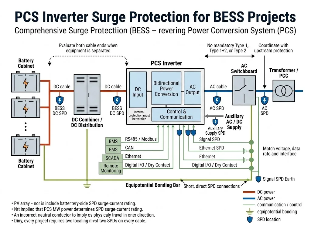
Um sistema de conversão de energia BESS conecta o circuito DC do lado da bateria a um quadro de distribuição AC, transformador, rede ou carga local. O mesmo PCS também pode se conectar a um BMS, EMS, plataforma SCADA, suprimento auxiliar e várias redes de comunicação.
Cada interface condutiva pode se tornar um caminho de entrada de surto. A proteção contra surto do inversor PCS deve, portanto, ser revisada como um problema de coordenação de interfaces — não como um pedido de um SPD genérico selecionado apenas com base na potência ou tensão nominal do PCS.
Índice
Um inversor PCS em um BESS precisa de proteção contra surto?
As interfaces AC, DC da bateria, de comunicação e auxiliares de um PCS BESS devem ser avaliadas para proteção contra surto coordenada.
A disposição final depende do manual do PCS, tensões de operação máxima, arranjos de aterramento, corrente de falta prospectiva, roteamento de cabos, exposição a raios, proteção interna do PCS e especificações do projeto.[1][2]
| Interface PCS | Direção de proteção | Confirmação principal |
|---|---|---|
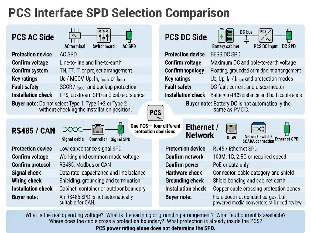
| Entrada DC | SPD DC do BESS selecionado para o circuito do lado da bateria atual | Tensão DC máxima, tensão pólo-terra, topologia de aterramento e corrente de falha |
| Conexão CA | SPD CA coordenado na PCS relevante ou limite do painel de controle | Tensão CA, sistema de aterramento, LPS, SPD a montante e posição de instalação |
| RS485 / CAN | SPD de sinal compatível com o circuito | Tensão de trabalho, taxa de dados, capacitância, blindagem e aterramento |
| Ethernet | SPD de rede onde o cabeamento de cobre cruza uma fronteira de proteção | Velocidade da rede, status PoE, conector, categoria de cabo e aterramento do escudo |
| Fonte auxiliar | SPD CA ou DC de acordo com o circuito auxiliar real | Tensão de alimentação, fonte, exposição do cabo e nível de resistência do equipamento |
Significado do comprador: “1 MW PCS” ou “1.500 V PCS” não é informação suficiente para seleção de SPD. O fornecedor precisa de dados elétricos e de instalação específicos para a interface.
Escopo: Este guia enfoca SPDs externos e de nível de gabinete para interfaces de potência, comunicação e auxiliar do PCS. Não cobre o design de circuito de surto de nível de componente como TVS, MOV, GDT ou PCB dentro do conversor.
Nesta página
- Defina o limite de proteção do PCS
- Proteção contra surtos do lado AC do PCS
- Proteção de entrada DC do PCS
- O SPD interno do PCS é suficiente?
- Interfaces de comunicação e auxiliares
- Aterramento e posição de instalação
- Processo de seleção de projeto
- Layouts comuns de BESS
- Erros comuns
- Checklist de OEM e projeto
- Perguntas frequentes
Defina o limite de proteção em torno do PCS
Um PCS é um conversor de energia bidirecional entre uma fonte de armazenamento de energia DC e um sistema elétrico AC. A IEC 62909-1:2025 abrange aspectos gerais e de segurança dos conversores de energia bidirecionais conectados à rede relevantes, com tensões de sistema que não ultrapassam 1.000 V AC ou 1.500 V DC.[1]
IEC 62477-1:2022 provides a broader safety framework for power electronic converter systems and their associated control, protection, monitoring and measurement functions.[2]
For surge protection, the PCS should not be treated as one closed box. The project team should identify every conductive line entering or leaving its enclosure.
Give special attention to cables that leave one cabinet, container, building or bonded zone and enter another. These routes can expose the PCS to conducted or induced transients even when the main enclosure already contains internal protection.[10]
The practical question is not only “Does the PCS contain an SPD?” The project should ask:
Which interfaces cross an external or internal protection boundary, what protection already exists, and what voltage can the PCS terminal safely withstand?
Como deve ser protegido o lado AC do PCS?
The PCS AC interface may connect to a low-voltage switchboard, transformer, point of common coupling or local microgrid. The correct SPD position depends on where a surge can enter and where the protected PCS terminal is located.
IEC 61643-11:2025 applies to SPDs connected to AC low-voltage power systems. IEC 61643-12:2020 provides selection, location, operation and coordination principles for AC power SPDs.[4][5]
Common AC-side evaluation points
| Posição | Protection purpose | O que deve ser confirmado |
|---|---|---|
| Main LV board or AC service boundary | Limits surges entering from the supply, transformer or external AC route | Lightning risk, LPS, supply arrangement, fault current and project rules |
| PCS AC terminal or local PCS panel | Limits residual or locally induced voltage close to the PCS interface | Distance from upstream SPD, cable route, coordination and PCS manual |
| Auxiliary AC distribution | Protects controllers, fans, HVAC, heaters, UPS and monitoring supplies | Separate source, voltage, earthing and cable exposure |
These are evaluation positions. They do not mean that every BESS needs an SPD at all three points.
Confirm voltage across each protection mode
Do not select the AC SPD only from the line-to-line voltage. The supplier needs the voltage across each intended protection mode, including line-to-neutral or line-to-earth where applicable.
The earthing arrangement must also be identified. TN-S, TN-C-S, TT and IT systems can require different connection configurations and different treatment of the neutral-to-earth path.
Do not state that every PCS AC connection requires Type 1, Type 1+2 or Type 2 protection. The required SPD Type depends on the installation boundary, lightning-current path, external LPS, upstream protection and applicable project rules.[5][10]
Check short-circuit safety separately from surge ratings
In, Imax and Iimp describe surge-test performance. They do not describe whether the SPD remains safe during a power-frequency fault.
Confirm the prospective short-circuit current, upstream fuse or breaker and the SPD manufacturer’s backup-protection conditions. The related SPD SCCR and Isccr guide explains this project check in more detail.
Como deve ser protegida a entrada DC do PCS?
The PCS DC input may connect directly to battery racks, a battery cabinet, a DC combiner or a separate DC distribution cabinet. This page focuses on the protection boundary at the PCS input and its coordination with the battery-side equipment.
IEC 61643-41:2025 applies to SPDs for DC power circuits and equipment rated up to 1,500 V DC. IEC 61643-01:2024 contains common SPD requirements used together with the relevant circuit-specific parts of the IEC 61643 series.[3][6]
A device marked “1,500 VDC” is not automatically suitable for a PCS battery input. Its declared application, continuous operating voltage, DC topology, protection modes, fault-current capability and disconnection method must be verified.
Battery DC is not automatically the same as PV DC
IEC 61643-31:2018 applies to SPDs connected to the DC side of photovoltaic installations. IEC 61643-41:2025 addresses SPDs for non-PV DC low-voltage power systems.[6][7]
A PV SPD should not be approved for a battery-side PCS interface merely because its voltage rating appears suitable. The manufacturer must declare the exact product suitable for the intended battery DC circuit and connection arrangement.
PCS DC-input data to confirm
- maximum DC input voltage, including maximum charging voltage;
- normal PCS operating range;
- voltage from each pole to earth;
- floating, grounded, bipolar or midpoint arrangement;
- prospective short-circuit current at the PCS terminal;
- existing protection inside the battery cabinet and PCS;
- required backup fuse, breaker or coordinated disconnector.
Uc must remain suitable during normal operation and the defined system conditions. Uc that is too low can increase stress and premature ageing. An unnecessarily high Uc can increase the voltage protection level reaching the PCS.
Battery cabinet protection and PCS input protection are different boundaries
| Ponto de proteção | Main protected area | Project decision |
|---|---|---|
| Battery cabinet output | Battery terminals, nearby BMS circuits and outgoing cable | Check whether local protection is already included and documented |
| DC combiner or distribution cabinet | Collection bus, branches and connected cable routes | Review the changed fault-current and bonding conditions |
| PCS DC input | PCS input terminals and nearby power electronics | Check residual voltage, local induction and coordination with remote SPDs |
Where the battery and PCS share one compact bonded enclosure, one coordinated arrangement may be sufficient. Where they are separated by external cables, different containers or exposed routes, both ends should be evaluated.
There is no universal cable-distance threshold for every BESS architecture. The decision must follow the actual protection zones, cable route, induced-voltage risk, equipment withstand level and project coordination study.[10]
Do not install an AC-only SPD on a battery DC bus unless the exact product and connection mode are explicitly rated for that DC application. DC fault interruption and disconnection conditions must be addressed by the declared product design.
For detailed selection across the complete battery-side system, use the separate BESS DC SPD guide. This page remains focused on the PCS input interface.
O SPD dentro do PCS é suficiente?
Some PCS products contain an internal AC SPD, DC SPD, PCB-level suppressor or another overvoltage-limiting component. This can protect a defined internal circuit, but it does not automatically prove that every external cable and remote cabinet is protected.
Internal protection may not cover:
- a remote battery cabinet;
- a long inter-container DC cable;
- the main AC service or upstream switchboard;
- a separately supplied auxiliary circuit;
- communication lines entering from another cabinet or building;
- surges induced outside the internal device’s coordination boundary.
Confirme estes itens antes de remover a proteção externa
A brochure statement such as “surge protection included” is not enough for project approval. Request the PCS circuit diagram, component schedule, SPD datasheet or technical manual.
External SPD removal should be supported by documented coordination. It should not be based only on a product feature icon or an assumption that internal protection covers the complete BESS.
Proteja interfaces de comunicação e auxiliares
A PCS can remain undamaged on its main power stage but still become unavailable because a communication port, controller input or auxiliary power supply has failed.
IEC 61643-21:2025 applies to SPDs connected to telecommunications and signalling networks. It also covers networks that provide power and data on the same conductors, including PoE applications. IEC 61643-22:2015 provides selection and application principles for these networks.[8][9]
| Interface PCS | Selection checks | Typical boundary to review |
|---|---|---|
| RS485 / Modbus | Working voltage, common-mode voltage, data rate, capacitance and shielding | Cable leaving the cabinet, container or building |
| CAN bus | CAN voltage, transmission rate, topology and line balance | Connection between PCS and remote battery controller |
| Ethernet / PoE | Network speed, PoE standard, cable category, connector and shield | Copper link between cabinets, containers or buildings |
| Digital I/O and dry contacts | Circuit voltage, current, signal behaviour and controller withstand | External alarms, emergency circuits and remote contacts |
| 24 VDC / 48 VDC auxiliary power | Maximum supply voltage, source, load withstand and grounding | External PLC, HMI, gateway or sensor supply |
An RS485 SPD is not automatically suitable for CAN. A battery-bus SPD is not suitable for a 24 V controller merely because both circuits are DC. Each interface requires its own voltage and signal review.
Use the dedicated Modbus surge protection guide e guia de seleção de protetores contra surto RJ45 when protocol-level model selection is required.
Optical fibre does not conduct a surge through the fibre itself. However, the media converter, power supply, metallic armour and nearby copper connections may still require protection.
Aterramento, ligação e posição de instalação
An SPD limits voltage through its complete connection path. Long or looped conductors add inductive voltage during a fast transient and can reduce the effective protection at the PCS terminal.
IEC 62305-4:2024 provides requirements for the design, installation, inspection, maintenance and testing of surge protection measures for electrical and electronic systems within structures.[10]
Install close to the intended boundary
Place the SPD near the cable entry, bus connection or equipment terminal that defines the intended protection boundary. Follow the PCS and SPD manufacturers’ instructions for the exact mounting position.
Keep connections short and direct
Avoid unnecessary loops and detours. Route the SPD connections to the protected conductors and bonding point as directly as practical.
Integrate all cabinets into the bonding design
Battery cabinets, PCS enclosures, AC switchboards, communication cabinets, cable screens and metallic containers should be included in the project equipotential-bonding design.
An SPD cannot compensate for a missing or poorly designed protective-earth and bonding system.
Review power and signal entries together
AC, DC and communication cables often follow different routes. Protecting the power entries while leaving an externally routed RS485 or Ethernet cable unreviewed can leave another surge path into the PCS controller.
Exact conductor length, cross-section, separation, backup protection and connection method must follow the applicable installation rules, PCS manual, SPD instructions and approved project drawings.
Um processo prático de seleção de SPD para PCS
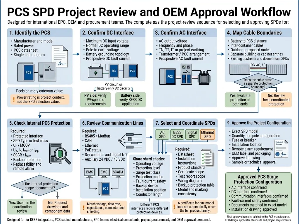
Map every conductive interface
List the main DC input, AC connection, auxiliary supplies, RS485, CAN, Ethernet, dry contacts, sensors and emergency circuits. Identify which cables leave the bonded enclosure.
Record the actual operating limits
Obtain the maximum DC voltage, AC voltage, pole-to-earth voltage, auxiliary voltage, signal voltage and equipment impulse-withstand information.
Confirm earthing and grounding
Identify the AC earthing system, DC grounding topology, insulation-monitoring arrangement, cable-shield method and equipotential-bonding structure.
Identify surge exposure and boundaries
Review the external LPS, outdoor routes, container separation, cable length and existing upstream or downstream SPDs.
Check surge and fault coordination
Verify Uc or MCOV, Up, surge test class, protection modes, prospective fault current, backup device and coordination with other SPDs.
Complete technical approval
Compare the proposed models and wiring with the PCS manual, EPC single-line diagram, applicable standards and project specification before ordering.
Como a lógica de proteção muda com o layout do BESS
Battery and PCS in One Container
Internal power routes may be short and remain within one bonded enclosure. Verify the protection already installed at each external entry before adding duplicate devices.
Separate Battery and PCS Containers
External DC and communication cables create separate boundaries. Review both cable ends, route exposure, bonding and coordination between local SPDs.
Utility-Scale PCS with Transformer
Review the PCS low-voltage AC terminal, transformer arrangement, main switchgear, available fault current, upstream protection and lightning-risk design.
Hybrid PV and BESS Project
Keep PV strings, battery DC circuits and converter interfaces clearly separated. Do not treat every 1,500 VDC circuit as the same SPD application.
IEC 62933-5-1:2024 provides general safety considerations for grid-integrated electrical energy storage systems. IEC 62933-5-2:2025 adds safety requirements for electrochemical energy storage systems across their life cycle.[11][12]
These standards establish the wider BESS safety context. The exact SPD must still be selected using the relevant AC, DC or signal product standard and the approved project design.
Erros comuns na proteção contra surto de PCS
| Erro | Por que cria risco | Better project practice |
|---|---|---|
| Selecting from PCS power only | MW or kW does not define voltage, fault current, grounding or exposure | Collect interface-specific electrical data |
| Using one SPD category everywhere | AC, battery DC and communication circuits have different conditions | Select each interface separately |
| Treating battery DC as PV DC automatically | Application scope, source behaviour and fault conditions can differ | Verify the declared BESS DC application |
| Assuming the internal SPD covers everything | The internal device may protect only one circuit or terminal | Request the circuit diagram and component data |
| Protecting only power lines | A communication or auxiliary transient can disable the controller | Review every externally routed conductor |
| Ignoring prospective fault current | The SPD or backup device may not safely clear a fault | Verify SCCR or Isccr and backup protection |
| Using long SPD connections | Connection inductance increases the voltage reaching the PCS | Use short, direct connections and proper bonding |
Informações necessárias antes de um pedido de SPD para PCS
A useful recommendation requires more than “BESS PCS” or “1,500 V inverter.” Prepare the following data before requesting a quotation, sample or OEM configuration.
Documents to Verify Before Model Approval
- PCS datasheet and interface schedule;
- AC and DC single-line diagrams;
- internal SPD or surge-protection component details;
- prospective AC and DC fault-current calculations;
- SPD datasheet and installation instructions;
- model-specific certificate or test-report scope;
- backup fuse or breaker coordination table;
- approved cabinet layout and wiring drawing.
A certificate for one model does not automatically cover every voltage, pole arrangement or module in the same product family. Match the model marking, report scope and project configuration.
Envie esses parâmetros para o fornecedor de SPD
LEEYEE can use these details to prepare a model shortlist and identify conditions that still require confirmation by the PCS manufacturer, system integrator or EPC.
CNSPD is LEEYEE’s surge protection-focused platform for global technical buyers. Final project approval remains subject to the PCS documentation, applicable standards and responsible engineering review.
Compartilhe seus requisitos de interface de PCS
Send the PCS datasheet, DC voltage range, AC single-line diagram, cable routes, communication interfaces, prospective fault currents and required project standard.
LEEYEE can review the AC, battery DC, signal, Ethernet, backup-protection and remote-alarm requirements before an OEM model or project sample is confirmed.
Perguntas mais frequentes
Does every BESS PCS need an SPD on both the AC and DC side?
Both interfaces should be assessed, but the final number and position of SPDs depend on the internal PCS protection, cable routing, upstream protection, lightning exposure, earthing, bonding and project specification.
Can a PV DC SPD be used at the battery input of a PCS?
Do not assume suitability from the voltage rating alone. Verify that the exact product is declared for the battery DC application, topology, fault current and required disconnection method.
Is a Type 2 SPD enough for the PCS AC side?
It may be appropriate at some local equipment or distribution positions, but it is not a universal answer. The required SPD Type depends on the installation boundary, LPS, upstream protection and applicable project rules.
Should an SPD be installed at both the battery cabinet and PCS?
Evaluate both ends when the equipment is separated by external or exposed cables, or when the ends form different protection boundaries. A compact system inside one bonded enclosure may use a different coordinated arrangement.
Does PCS power determine the SPD surge-current rating?
No. PCS power and SPD surge-current capability describe different conditions. SPD selection depends on surge exposure, installation position, test class, coordination and project risk.
Can the PCS internal SPD replace all external SPDs?
This cannot be concluded without documentation. Confirm which interface the internal device protects, its ratings, connection mode, coordination limits and whether remote equipment remains outside its protection boundary.
Does a fibre communication link need a signal SPD?
The optical fibre itself does not conduct a surge. The associated power supply, media converter, metallic armour, Ethernet patch cable and other conductive connections still need to be reviewed.
What information is most important for a PCS DC SPD quotation?
Provide the maximum DC voltage, operating range, grounding arrangement, pole-to-earth voltage, prospective fault current, cable route, installation position and existing protection.
Should a signal SPD be selected only by protocol name?
No. Protocol name alone is insufficient. Confirm the working voltage, common-mode voltage, data rate, capacitance, connector, shielding and grounding arrangement.
Referências
- International Electrotechnical Commission, IEC 62909-1:2025, Bi-directional grid-connected power converters — Part 1: General and safety requirements. Página de publicação oficial da IEC.
- International Electrotechnical Commission, IEC 62477-1:2022, Safety requirements for power electronic converter systems and equipment — Part 1: General. Página de publicação oficial da IEC.
- International Electrotechnical Commission, IEC 61643-01:2024, Low-voltage surge protective devices — Part 01: General requirements. Página de publicação oficial da IEC.
- International Electrotechnical Commission, IEC 61643-11:2025, Low-voltage surge protective devices — Part 11: Surge protective devices connected to AC low-voltage power systems — Requirements and test methods. Página de publicação oficial da IEC.
- International Electrotechnical Commission, IEC 61643-12:2020, Low-voltage surge protective devices — Part 12: Surge protective devices connected to low-voltage power systems — Selection and application principles. Página de publicação oficial da IEC.
- International Electrotechnical Commission, IEC 61643-41:2025, Low-voltage surge protective devices — Part 41: Surge protective devices connected to DC low-voltage power systems — Requirements and test methods. Página de publicação oficial da IEC.
- International Electrotechnical Commission, IEC 61643-31:2018, Low-voltage surge protective devices — Part 31: Requirements and test methods for SPDs for photovoltaic installations. Página de publicação oficial da IEC.
- International Electrotechnical Commission, IEC 61643-21:2025, Low-voltage surge protective devices — Part 21: Surge protective devices connected to telecommunications and signalling networks — Requirements and test methods. Página de publicação oficial da IEC.
- International Electrotechnical Commission, IEC 61643-22:2015, Low-voltage surge protective devices — Part 22: Surge protective devices connected to telecommunications and signalling networks — Selection and application principles. Página de publicação oficial da IEC.
- International Electrotechnical Commission, IEC 62305-4:2024, Protection against lightning — Part 4: Electrical and electronic systems within structures. Página de publicação oficial da IEC.
- International Electrotechnical Commission, IEC 62933-5-1:2024, Electrical energy storage systems — Part 5-1: Safety considerations for grid-integrated EES systems — General specification. Página de publicação oficial da IEC.
- International Electrotechnical Commission, IEC 62933-5-2:2025, Electrical energy storage systems — Part 5-2: Safety requirements for grid-integrated EES systems — Electrochemical-based systems. Página de publicação oficial da IEC.
- ABB, Switching & Protection of 1500 V DC Bus in Power Conversion Systems, application note addressing PCS used in PV, BESS and hydrogen applications. Official ABB application note.
