
Um automatic transfer switch for a generator backup system should not be selected as an isolated switch. The ATS must match the utility source, generator output, generator controller, backed-up load, phase and neutral arrangement, transfer sequence, protection design and project requirements.
Índice
Quick Answer: How Does a Generator ATS Work?
While utility power is acceptable, the ATS keeps the backed-up load on the normal source. If the utility becomes unacceptable for the configured start delay, the ATS or associated controller can issue a generator-start request. The generator controller then starts the genset and builds voltage and frequency.
The ATS should transfer the load only after the generator source reaches the controller's acceptable conditions and any configured transfer delay has expired. When utility power returns and remains acceptable for the retransfer delay, the load returns to utility. A stop or cooldown delay can then allow the generator to run unloaded before shutdown.[2]
Do not assume that every automatic transfer switch includes a generator engine-start output. Some transfer-switch controllers provide dedicated engine-start contacts; other compact source-transfer devices only transfer between AC sources that have already become available. The actual generator-start interface must be confirmed before ordering.[3]
Generator ATS Selection at a Glance
Before comparing ATS models, confirm these project conditions first.
| Confirm First | Why It Changes ATS Selection |
|---|---|
| Generator voltage and phase | Determines compatible ATS voltage and pole configuration |
| Maximum backed-up load current | Determines the continuous-current requirement of the ATS |
| Generator controller model | Determines whether and how generator auto-start can be coordinated |
| Neutral and earthing arrangement | Affects whether the neutral must be switched and whether 3P or 4P is appropriate |
| Motor / transformer loads | Starting and inrush current can affect switching duty and generator performance |
| Maximum acceptable interruption | Determines whether ordinary open-transition transfer is sufficient |
| ATS device or complete panel | Defines whether the supplier provides only the transfer device or an engineered cabinet |
Where Does the ATS Sit in a Generator Backup System?
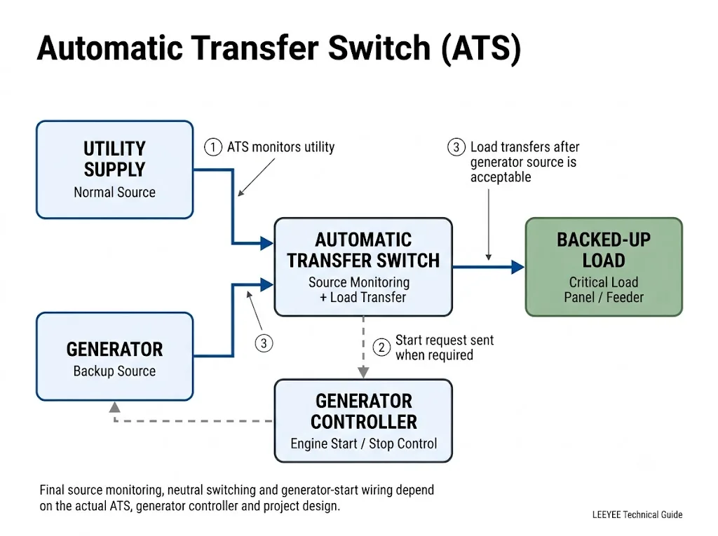
The ATS is installed at the point where a backed-up load must select between the normal utility source and the generator source. Its location is determined by the electrical distribution architecture, not simply by how close it is to the generator.
In a whole-section backup design, the ATS can feed an entire backed-up distribution section. In a selected-load design, it can feed only a critical-load panel or dedicated feeder while non-critical loads remain outside the generator-backed path.
What Happens When Utility Power Fails?
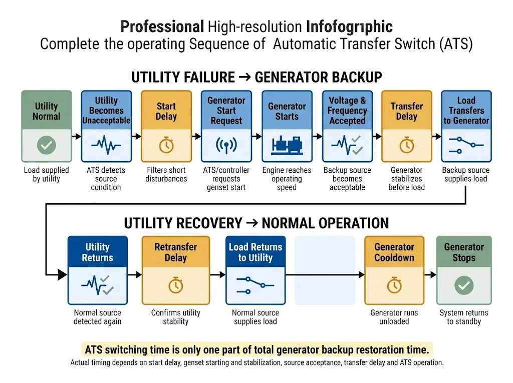
A professional generator backup sequence involves several decisions. “Utility fails, generator starts, ATS switches” is only the simplified summary.
- The ATS monitors the normal source. Depending on the controller, monitoring can include voltage, frequency and phase-related conditions. The available functions and trip or pickup settings are product-specific.[2]
- A start delay can filter short disturbances. Cummins describes a start time delay as a means of preventing unnecessary generator starts or transfer sequences for short-duration disturbances of the normal source.[2]
- The generator receives a start request. If the transfer-control system includes an engine-start interface, the ATS/controller changes the required contact state or sends the specified start command to the generator controller. Schneider Electric / ASCO documentation shows that contact logic can differ by equipment.[3]
- The generator starts and builds its output. The genset controller handles engine starting and generator operation. Engine running status alone does not prove that the generator source is ready to carry the load.
- The ATS verifies that the backup source is acceptable. Generator voltage and, where monitored, frequency must reach the controller's acceptable limits before the transfer sequence proceeds.[2]
- The transfer delay expires. A transfer delay can allow the generator output to stabilize before the load is applied.[2]
- The ATS transfers the load. In a conventional open-transition arrangement, the connected source is opened before the alternative source is connected. Other transition modes require transfer equipment and controls specifically designed for those functions.[1]
What Happens When Utility Power Returns?
A generator ATS does not necessarily return the load to utility the instant normal voltage reappears. A recently restored source may still be unstable.
- The ATS detects the returning normal source. Utility power must return to the controller's acceptable source conditions.
- The retransfer delay begins. The delay allows the normal source to remain stable before the load is moved away from generator power and helps reduce repeated transfer/retransfer cycles when utility power is unstable.[2]
- The load returns to utility. After the retransfer conditions are satisfied, the normal source again supplies the backed-up load.
- The generator can continue running unloaded. A generator stop or cooldown delay can keep the genset operating without load after retransfer.[2]
- The generator returns to standby. The generator controller completes its shutdown sequence and waits for the next valid start request.
How Long Does Generator Backup Transfer Take?
There is no single universal transfer time from utility failure to generator-powered load. Total restoration time depends on the control settings and the generator itself.
This is why a catalogue value such as “transfer switching time” should not be presented as the complete outage-to-generator recovery time.
ATS Controller vs Generator Controller: Who Does What?
A useful way to understand the system is to treat the ATS controller as the source decision controller and the genset controller as the generator machine controller.
The responsibility split below is typical rather than universal. The actual controller and wiring documentation takes priority.
| Função | Typical Responsibility | Confirmação do projeto |
|---|---|---|
| Monitor utility source | ATS / transfer controller | Voltage, frequency and phase-monitoring functions actually provided |
| Request generator start | ATS/controller if an engine-start output is provided | Contact logic, terminals and interface requirements |
| Crank and start engine | Generator controller | Generator controller model and remote-start input |
| Engine protection | Generator controller | Use the genset manufacturer's control documentation |
| Accept emergency source | ATS / transfer controller | Generator voltage and frequency acceptance settings |
| Transfer the load | Transfer switching equipment | Transition type, poles, current rating and switching duty |
| Cooldown / shutdown | Coordinated ATS and generator control | Where the stop delay is implemented and how shutdown is commanded |
Procurement conclusion: the generator controller model becomes an important ATS enquiry parameter whenever automatic genset starting is part of the project.
Does Every Automatic Transfer Switch Start the Generator?
No. Automatic source transfer and automatic engine starting are related functions, but they should not be treated as the same feature.
ASCO transfer-switch documentation identifies dedicated engine-start terminals and shows that contact logic and terminal arrangements vary by transfer-switch model.[3] A compact source-transfer device may instead depend on a separate controller or another system to make the generator source available.
How Should You Select an ATS for a Generator Backup System?
1. Confirm Utility and Generator Voltage
The utility voltage, generator output voltage and ATS rated operating voltage must be compatible with the intended system. Confirm the actual line-to-line and line-to-neutral arrangement rather than relying only on a country-level nominal voltage.
2. Confirm Frequency
Confirm whether the project operates at 50 Hz or 60 Hz and whether both the ATS controller and generator are suitable for that system. Source-monitoring functions must also be configured for the intended frequency.
3. Confirm Single-Phase or Three-Phase Architecture
Single-phase and three-phase generator systems require different conductor and pole arrangements. However, phase count alone does not determine whether the neutral should be switched.
4. Decide Whether the Neutral Must Be Switched
Neutral switching depends on the facility grounding arrangement, generator neutral treatment and any ground-fault protection scheme. Cummins notes that the choice between a solid neutral connection and a switched neutral depends on how the distribution system is grounded and whether ground-fault protection is used.[2]
5. Select ATS Current From the Load It Must Carry
ATS continuous-current selection starts from the current carried by the transfer equipment. Cummins describes continuous current as being selected according to the total connected-load requirement in a manner comparable to conductor sizing.[2]
Generator nameplate capacity remains useful because it establishes the available source capacity, but generator kVA and ATS amperes are different ratings.
For example, a 30 kVA, 400 V three-phase generator has a calculated full-load current of about 43 A. The final ATS selection must still consider the backed-up load, switching duty, utilization category, motor or transformer inrush, protection coordination and the equipment manufacturer's ratings.
6. Identify Motor, Pump, Compressor and Transformer Loads
High-inrush or inductive loads can affect both generator performance and transfer-switch application. Do not select an ATS only from steady-state current when the backed-up feeder includes large motors, pumps, compressors or transformers.
Confirm the actual utilization category, permitted load type and switching duty in the ATS technical documentation.
7. Confirm Short-Circuit and Upstream Protection
A transfer switch is part of a larger protection system. Its short-circuit withstand or conditional rating, the upstream overcurrent protective device and the installation fault level must be reviewed together.
Do not assume that an ATS provides overload, short-circuit or surge protection unless those functions are explicitly included and rated in the specific equipment.
Must Generator Capacity and ATS Current Rating Be the Same?
Não. Generator capacity is commonly expressed in kVA or kW. ATS continuous-current capability is expressed in amperes together with voltage, switching and short-circuit ratings.
A generator can supply several separately protected loads through more than one ATS. Conversely, one ATS may serve only a selected critical-load panel even when the generator has additional spare capacity.
Single-Phase vs Three-Phase Generator ATS Selection
Use this table as an initial engineering discussion only. Neutral switching remains project-specific.
| Sistema | ATS Arrangement to Evaluate | Main Confirmation |
|---|---|---|
| Monofásico | 2-pole switching may be used where both line and neutral are required to switch | Voltage, conductor arrangement and neutral treatment |
| Three-phase with solid neutral | 3-pole phase transfer may be possible | Grounding, generator neutral and ground-fault protection |
| Three-phase with switched neutral | 4-pole transfer arrangement | Generator neutral, earthing architecture and project requirements |
Procurement conclusion: pole count should follow the actual neutral and grounding design, not a simplified phase-count rule.
Open Transition, Delayed Transition or Closed Transition?
Open Transition
The connected source is opened before the alternative source is connected. This break-before-make approach is widely used where a short transfer interruption is acceptable.
Special Transition Requirements
Delayed, programmed or closed-transition systems require transfer equipment and controls specifically designed for those operating modes. Closed transition introduces source synchronization and paralleling considerations.
IEC 60947-6-1:2026 includes provisions for automatic transfer switching equipment, bypass/isolation transfer switching equipment, closed-transition ATSE and stand-alone ATS controllers.[1]
Do You Need an ATS Device or a Complete ATS Panel?
This is an important procurement question. A switchboard manufacturer may need only the transfer device. A generator integrator or project contractor may need a complete assembled cabinet.
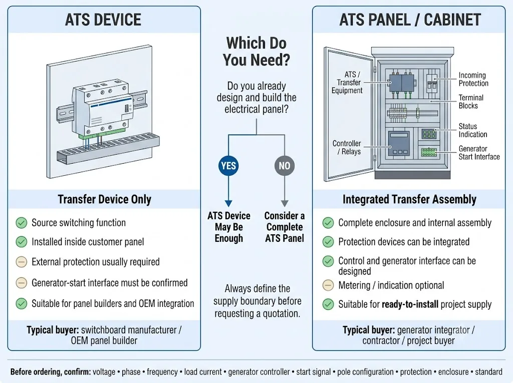
| Requisito | ATS Device | ATS Panel / Cabinet |
|---|---|---|
| Transfer switching equipment | Incluído | Included in the assembly |
| Invólucro | Provided by the panel builder | Normally part of the specified assembly |
| Incoming / outgoing protection | Normally external to the transfer device | Can be integrated when specified |
| Generator-start interface | Must be confirmed by model | Can be engineered around the generator controller |
| Metering / indication / communication | Product dependent | Can be included according to project scope |
Procurement conclusion: define the supply boundary before requesting a quotation. “ATS” can mean only the transfer device or a complete engineered transfer assembly.
When Are Manual Operation and Bypass Useful?
Funcionamento manual
Manual operation can support commissioning, maintenance, controlled testing and emergency service procedures. The exact method and safe operating conditions depend on the transfer-switch design and manufacturer's instructions.
Bypass / Isolation
Bypass/isolation becomes relevant when transfer equipment must be maintained while another controlled power path remains available. It is generally associated with engineered systems where maintainability and availability justify the additional equipment.
IEC 60947-6-1:2026 includes dedicated requirements for bypass/isolation transfer switching equipment.[1]
Can Several ATS Units Use One Generator?
Yes, this is possible in a properly engineered system. The generator-start control scheme, contact ratings, isolation and controller logic must be designed for the actual equipment.
Schneider Electric / ASCO publishes an example in which several transfer switches are connected to a common generator and their engine-start contacts are coordinated so that loss of normal power at a participating transfer switch can request generator start.[4]
Common Generator ATS Selection Mistakes
| Wrong Assumption | Possible Project Problem | What to Confirm Instead |
|---|---|---|
| Every automatic ATS starts a genset | Backup input never becomes available | Engine-start interface and controller logic |
| ATS current should copy generator kVA | Incorrect transfer-device sizing | Actual source current and backed-up load current |
| Three-phase always means one pole arrangement | Neutral or grounding mismatch | Earthing system and neutral treatment |
| Fast switching time equals fast generator recovery | Unrealistic interruption expectation | Full start, stabilization and transfer sequence |
| ATS replaces circuit protection | Incomplete protection design | Breakers, fuses, fault level, earthing and other required protection |
Where Can a Compact LEEYEE ATS Fit?
LEEYEE supplies compact low-voltage automatic transfer solutions for applications within the documented ratings of the selected model. A compact ATS can be appropriate where two compatible AC sources must be transferred and the required current, voltage, pole arrangement, utilization category and switching duty are within the product specification.
For a generator application, however, the transfer device must not be evaluated in isolation. If the generator normally remains stopped, the system also needs a valid method for requesting generator start and confirming that the backup source has become acceptable.
For current LEEYEE transfer-switch product information, model data and wiring details, review the LEEYEE automatic transfer switch product page.
Which Standards Should Be Checked for a Generator ATS Project?
For IEC-oriented projects, the current international transfer-switching standard is IEC 60947-6-1:2026, Edição 4.0. It covers transfer switching equipment and includes requirements relevant to automatic transfer switching, stand-alone ATS controllers, bypass/isolation equipment and closed-transition equipment.[1]
For North American projects, UL Solutions identifies UL 1008 for automatic transfer switches used in emergency systems and optional standby systems.[5]
Before Ordering an Automatic Transfer Switch for a Generator
A useful quotation starts with a complete system brief. Sending only “63 A ATS” or “100 kVA generator” leaves important engineering questions unanswered.
Generator ATS Project Checklist
Need a Generator ATS Configuration Review?
Send the utility voltage, generator voltage, phase, backed-up load current, generator controller model and start-signal information. LEEYEE can help review whether a suitable transfer-switch configuration matches the electrical requirements and identify which conditions still need project confirmation.
Frequently Asked Questions About Generator ATS Systems
Does an ATS automatically start the generator?
What signal does an ATS send to a generator?
Does the ATS transfer immediately when the generator starts?
How long does an ATS take to transfer to generator power?
Why does the generator keep running after utility power returns?
Should generator kVA equal the ATS ampere rating?
Do I need a 2P, 3P or 4P ATS for a generator?
Can one generator supply several ATS units?
Do I need an ATS device or a complete generator ATS panel?
When should bypass/isolation be considered?
Is a fast ATS the same as a UPS?
Referências
- International Electrotechnical Commission (IEC). IEC 60947-6-1:2026, Low-voltage switchgear and controlgear — Part 6-1: Multiple function equipment — Transfer switching equipment. Edition 4.0. Official IEC information: IEC 60947-6-1:2026.
- Cummins Power Generation. T-011 Transfer Switch Application Manual. Used for source monitoring, start delay, transfer delay, retransfer delay, generator stop/cooldown delay, continuous-current selection and neutral-switching application principles. Official document: Cummins Transfer Switch Application Manual.
- Schneider Electric / ASCO Power Technologies. Engine Start Signal and Transfer Switch Technical Guidance. Used for engine-start contact arrangements and model-dependent start-control logic. Official technical information: ASCO Engine Start Technical FAQ.
- Schneider Electric / ASCO Power Technologies. Multiple Transfer Switches With a Common Generator. Used as an equipment-specific example showing that several ATS units can coordinate generator-start contacts in an engineered system. Official technical information: ASCO Multiple ATS / Common Generator FAQ.
- UL Solutions. Serviços de certificação e avaliação de comutadores. Identifies UL 1008 for automatic transfer switches used in emergency and optional standby systems. Official UL information: UL Transfer Switch Information.
