
Not every automatic transfer switch needs or includes Modbus communication. A compact ATS can perform normal automatic source transfer, manual switching and source-status indication without having an RS485 or Modbus interface.
This guide is therefore not a claim that every LEEYEE compact ATS supports Modbus. It explains how BMS integrators, PLC panel builders and project engineers should verify communication capability when a project specifically requires ATS Modbus RTU communication over RS485.
Índice
Quick Answer: Does an ATS Support Modbus?
Only if the selected ATS controller is specifically designed and documented for it. An RS485 interface may be used for Modbus RTU communication, but the controller must explicitly support the protocol and provide the necessary communication documentation.[1][2]
For a BMS or PLC project, confirm the exact ATS controller model, RS485 terminals, Modbus RTU support, serial settings, register map and read/write permissions before the ATS is approved.
Remote monitoring also does not automatically mean remote transfer control. Some controllers allow reading only, while others may permit selected settings or transfer commands under defined operating conditions.[4][6]
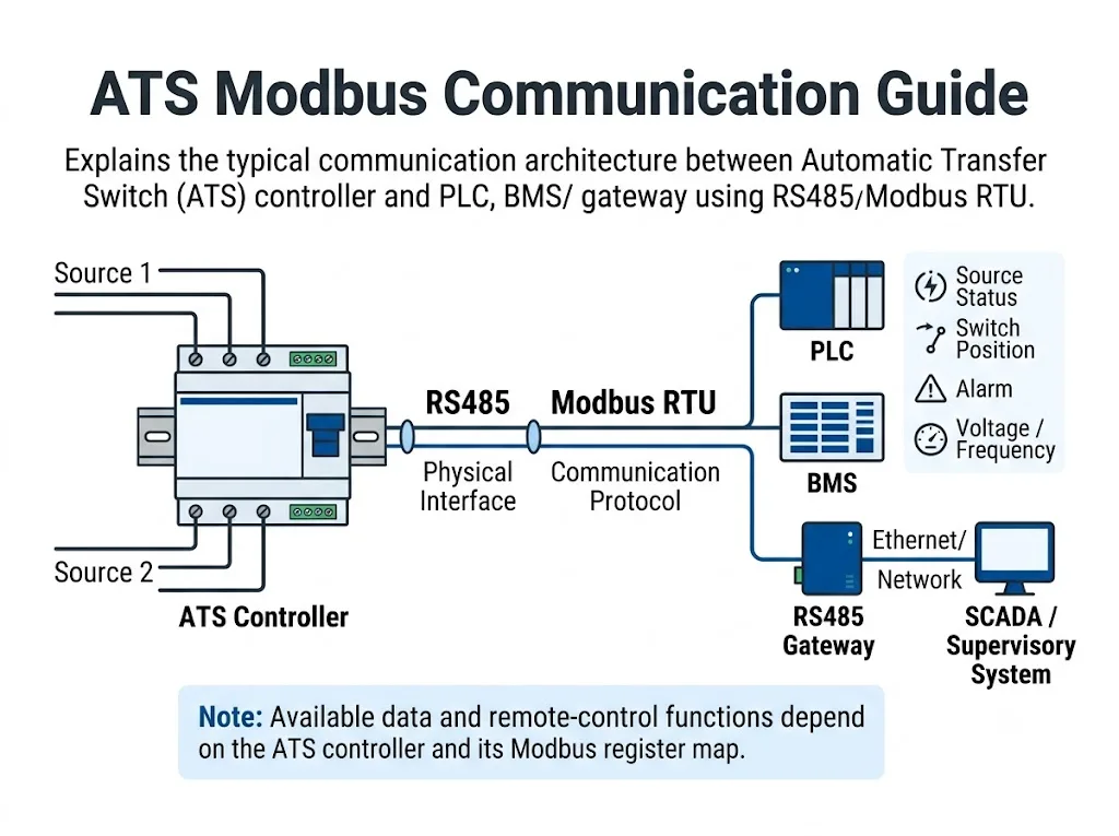
Standard ATS Function vs Communication Function
This distinction is important when selecting a compact ATS. The transfer-switch function and the communication function are separate engineering requirements.
| Requisito | Standard ATS Function | Needs Separate Communication Confirmation? |
|---|---|---|
| Automatic source transfer | Core ATS function | Não |
| Manual operation | Common compact ATS function | Não |
| Source / switch indication | May be shown locally on the device | Only if the status must be exported remotely |
| BMS monitoring | Not implied by normal transfer operation | Sim |
| PLC communication | Not implied by normal transfer operation | Sim |
| RS485 \/ Modbus RTU | Controller-dependent | Sim |
| Remote transfer command | Not universal | Yes, including control permissions and safety logic |
For a compact ATS project, first select the correct transfer-switch configuration. Add Modbus or BMS integration only when the project actually requires communication.
What Should Be Confirmed Before ATS Modbus Integration?
A specification that says only “RS485” is not enough for a BMS or PLC engineer to complete an integration. Before the panel design is frozen, confirm the following items.
The controller identity and communication documentation are the most important items to verify first.
| Verificar | Por que Isso Importa | O que Confirmar |
|---|---|---|
| Controller model | Registers and communication functions are controller-specific. | Exact controller model, hardware configuration and relevant software or firmware version. |
| Physical interface | The project needs a compatible serial electrical interface. | Whether the proposed controller actually provides RS485 terminals. |
| Protocolo | RS485 does not define the application protocol by itself. | Whether the controller specifically supports Modbus RTU. |
| Serial settings | The ATS and supervisory device must use compatible settings. | Device address, baud rate, parity and stop-bit options. |
| Register map | The register map tells the BMS or PLC what data is actually available. | Controller-specific addresses, data types, access rights and supported Modbus functions. |
| Remote control | Monitoring does not automatically include transfer commands. | Whether communication control is supported and under which operating conditions. |
If these documents are unavailable, do not treat the ATS as a confirmed Modbus-compatible device for the project.
RS485 vs Modbus RTU: What Is the Difference?
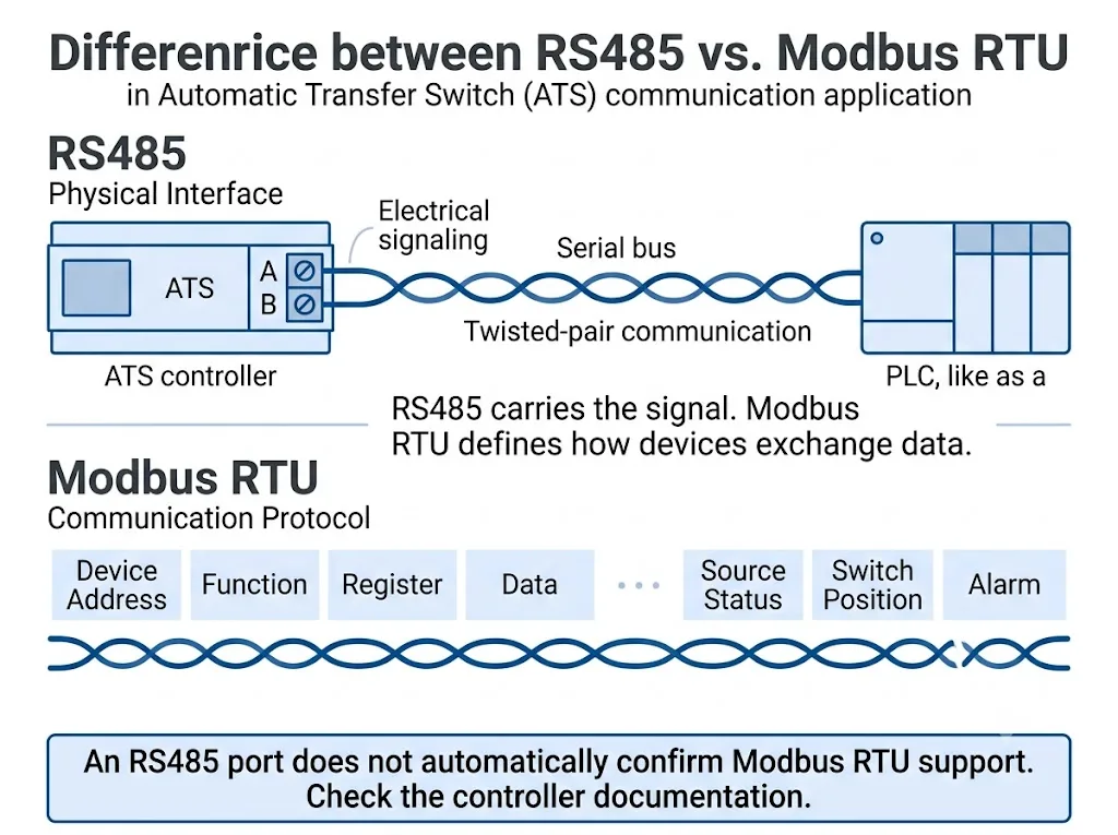
RS485 and Modbus RTU are related, but they are not the same thing. Modbus is an application-layer messaging protocol that defines requests, replies, data objects and function codes.[1] Modbus serial-line systems can use an EIA/TIA-485 electrical interface for device communication.[2]
Why the ATS Modbus Register Map Matters
The Modbus protocol defines how devices exchange data, but it does not define a universal register number for ATS-specific information such as Source 1 Available, Switch Position ou Transfer Fault. Those mappings are created by the controller manufacturer.[1]
Published ATS communication tables demonstrate why this matters. For example, Socomec publishes product-specific Modbus tables containing controller identification, version information, register addresses, data types and read/write functions.[5]
What ATS Data Can a BMS or PLC Read?
If the selected controller supports Modbus RTU, the available data may include source states, switch position, operating mode, alarms, electrical measurements, timers and other diagnostic information. The exact point list remains controller-specific.[3][5]
| Data Category | Possible Examples | Project Meaning |
|---|---|---|
| Source status | Source 1 / Source 2 available | Helps the supervisory system determine which incoming supply is healthy. |
| Switch position | Position 1, OFF/0, Position 2 | Shows which transfer-switch position is reported by the controller. |
| Operating mode | Automatic, manual, local or remote state | Helps identify how the ATS controller is currently operating. |
| Alarm / fault | Transfer fault, source fault, position error | Supports maintenance alarms and diagnostic logic. |
| Measurements | Voltage or frequency where supported | May provide additional source-condition information. |
| Timers / events | Timer states or transfer events | Can support commissioning and troubleshooting. |
These are possible categories, not guaranteed functions of a standard compact ATS.
Can Modbus Remotely Control an ATS?
Sometimes, but only when the controller explicitly supports communication-based control. Modbus support by itself does not prove that remote transfer commands are available.
Monitoring Only
The BMS or PLC reads ATS status and alarms but cannot issue switching commands.
Remote Configuration
Selected settings may be writable when the controller and access mode permit changes.
Communication Control
Some ATS controllers allow transfer commands under controller-specific operating and safety logic.
ABB ATS022 documentation is one example of this distinction. It separates Local and Remote configurations and applies different permissions to remote reading, parameter changes and commands.[4]
Schneider Electric's TransferPacT documentation also treats communication control as a specific function rather than an automatic consequence of Modbus support.[6]
ATS Modbus vs Dry Contact Monitoring
If a project only needs a few simple status signals, dry contacts may be sufficient. Modbus becomes more useful when the BMS or PLC needs many structured data points, detailed alarms, measurements or communication with multiple devices.
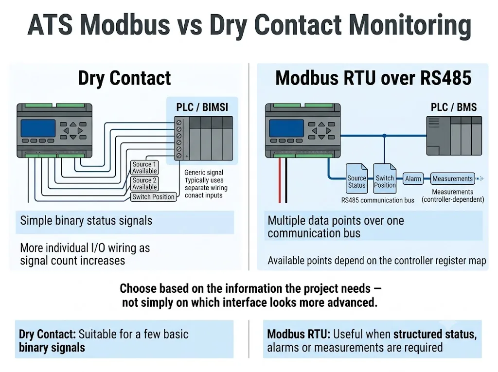
| Requisito | Dry Contact | Modbus RTU |
|---|---|---|
| Basic binary status | Simple where suitable auxiliary contacts are provided | Possible when corresponding registers are available |
| Many data points | Requires additional individual I/O wiring | Multiple mapped points can share one communication network |
| Measurements | Normally needs separate measuring signals or devices | Possible only if the controller measures and exposes the values |
| Remote commands | Requires a suitable external control circuit and inputs | Possible only when specifically supported |
For compact ATS applications, choose the simplest interface that meets the actual project requirement.
How Would a Modbus-Capable ATS Connect to a BMS or PLC?
When an ATS controller is confirmed to support Modbus RTU, typical integration may use one of the following architectures:
- ATS controller → RS485 / Modbus RTU → PLC for panel-level monitoring or automation logic.
- ATS controller → RS485 / Modbus RTU → BMS for building-level monitoring and permitted supervisory functions.
- ATS controller → RS485 / Modbus RTU → gateway → upper-level system where the project requires protocol conversion.
A gateway does not replace the ATS communication documentation. The integrator still needs the controller-specific register map and point definitions.
Utility-generator projects
A compact ATS can be used in a utility-generator transfer application without necessarily having Modbus communication. Generator-start control, ATS switching and BMS communication are separate control functions and should be verified independently.
If the project requires generator status, start commands, ATS position or source conditions to be shared with a supervisory system, define those points before selecting the final control architecture.
RS485 Wiring and Commissioning Checks
For controllers that are confirmed to support Modbus RTU, the Modbus Serial Line Protocol and Implementation Guide describes RS485 network principles including bus topology and line termination.[2] Product-specific terminal names, cable requirements and termination methods must still come from the selected controller documentation.
- Terminal identification: follow the controller wiring diagram instead of assuming A/B labels are identical across manufacturers.
- Network topology: use the topology required by the controller documentation and Modbus network design.
- Termination: verify whether termination is internal, selectable or external.
- Reference and shielding: follow the controller instructions for signal common and shield connection.
- Device address: configure each device according to the project's addressing plan.
- Serial parameters: baud rate, parity and stop bits must match across the network.
Why Is the ATS Not Responding to Modbus?
For a controller that has already been confirmed as Modbus-capable, communication problems usually need to be checked systematically.
| Symptom | Verificar primeiro | Por quê |
|---|---|---|
| No response | RS485 wiring, address and serial settings | A wiring or configuration mismatch can prevent communication completely. |
| Communication is intermittent | Topology, termination and interference | Physical-layer issues may appear as unstable communication. |
| Values appear incorrect | Register map, data type and controller version | Using the wrong documentation can cause incorrect interpretation. |
| Reading works but writing fails | Read/write permissions and controller operating mode | Some controllers intentionally restrict remote parameter changes or commands.[4] |
| Command is accepted but no transfer occurs | Source availability, communication-control enable and transfer conditions | Communication-capable ATS equipment may still apply transfer logic and safety conditions.[6] |
Before Ordering: Define the Communication Requirement First
For a normal compact ATS application, communication may not be necessary. If the project specifically requires BMS, PLC, RS485 or Modbus RTU integration, define that requirement before approving the ATS model.
Send the supplier these project requirements:
- Sistema monofásico ou trifásico
- 2P, 3P or 4P requirement
- Corrente nominal
- Utility-generator or utility-utility application
- Required ATS status points
- Required alarm points
- Dry-contact requirement
- RS485 requirement
- Modbus RTU requirement
- BMS or PLC interface requirement
- Monitoring-only or remote-control requirement
- Required communication documents
Does Your ATS Project Require RS485 or Modbus?
Send us the system voltage, pole configuration, rated current, application, required BMS or PLC points and whether remote communication is required. LEEYEE will confirm whether the requested communication function is available for the proposed ATS configuration or whether a different control solution should be considered.
ATS Modbus Communication FAQ
Does every compact ATS support Modbus?
No. A compact ATS can perform automatic source transfer without any Modbus interface. Communication capability depends on the controller configuration and must be confirmed separately.
O RS485 é o mesmo que Modbus RTU?
No. RS485 is an electrical serial interface, while Modbus is a communication protocol. An RS485 port alone does not prove Modbus RTU support.[1][2]
What ATS status can a BMS read?
If the controller supports Modbus, possible points may include source status, switch position, operating mode, alarms, voltage, frequency and timer information. The exact point list must come from the controller-specific register map.[3][5]
Can a PLC remotely transfer an ATS through Modbus?
Only if the controller explicitly supports communication-based control. Some controllers provide monitoring only, while others require remote-control permission and defined operating conditions.[4][6]
Do I need a Modbus register map?
Yes. The register map identifies which controller addresses correspond to status, alarms, measurements, settings or commands.
Should I choose Modbus or dry contacts for ATS monitoring?
Choose according to the project point list. Dry contacts can be sufficient for a few simple binary signals. Modbus is more useful when the project requires a larger structured data set.
Referências
- Modbus Organization. MODBUS Application Protocol Specification V1.1b3. View official specification.
- Modbus Organization. Modbus Serial Line Protocol and Implementation Guide V1.02. View Modbus specifications.
- Eaton. ATC-300+ Modbus Communications Guide, IB140004EN. View Eaton guide.
- ABB. ATS022 Installation and Operating Instructions, 1SDH000760R0002. View ABB documentation.
- Socomec. ATyS Modbus Communication Tables. View Socomec communication table.
- Schneider Electric. TransferPacT Active Automatic and Automatic User Guide — Modbus Communication and Communication Control. View Modbus communication documentation.
