
Dual-Source ATS Selection for B2B Projects
A dual power automatic transfer switch transfers a load between two alternative power sources. But “dual power” alone is not enough to specify the correct ATS. For a real panel, generator or OEM project, the source pair, neutral arrangement, pole count, electrical ratings, controller logic, load duty and short-circuit coordination all affect the final configuration.[1]
This guide is for panel builders, distributors, electrical contractors, generator integrators and OEM buyers who need to convert a two-source requirement into a usable ATS specification—not simply understand what an automatic transfer switch is.
Índice
How Should You Select a Dual Power Automatic Transfer Switch?
Start with the two power sources, not the ampere rating. A utility–utility system and a utility–generator system can use the same basic transfer concept, but they may require different source-priority logic, neutral treatment, controller functions and transfer sequences.
The items below are the core decisions a buyer should clarify before fixing the ATS model.
| Confirm First | Typical Options | Why It Changes Selection |
|---|---|---|
| Source pair | Utility–utility; utility–generator; other approved AC source combinations | Changes source priority, failure logic, return logic and control interfaces |
| Sistema elétrico | Monofásico ou trifásico | Affects voltage arrangement and pole selection |
| Neutral treatment | Solid neutral or switched neutral | Must match the source, grounding arrangement and project design |
| Postes | 2P, 3P or 4P | Defines which circuit conductors are transferred |
| Classificações | Voltage, frequency, current and load duty | Must match the actual electrical system and application |
| ATS architecture | PC Class or CB Class where applicable | Changes the switching and short-circuit protection arrangement |
| Controller logic | Priority, delays, generator start and status I/O | Determines how the system behaves before, during and after transfer |
| Project documents | Applicable standard, datasheet, certificate or test-report scope | Compliance must be verified for the exact project and model |
Significado do comprador: “I need a 400 A dual power ATS” is not a complete RFQ. Add the source types, voltage, phase, neutral requirement, poles, load type, controller logic and project-document requirements before comparing quotations.
What Does “Dual Power” Mean in an ATS?
IEC 60947-6-1:2026 covers transfer switching equipment used to transfer a load between power supply sources, including automatic transfer switching equipment and stand-alone ATS controllers within its scope.[1] In procurement language, “dual power” emphasizes that the system has two alternative sources available to the load.
The important issue is not whether the sources are called Source I, Source II, normal, preferred, alternate or standby. The project needs to define which source normally supplies the load, what makes that source unacceptable, when the alternate source is allowed to take over and what happens after the preferred source returns.
Is a Dual Power ATS Different From a Standard ATS?
In many supplier catalogues and search queries, dual power ATS e interruptor de transferência automático describe the same basic two-source transfer function. “Dual power” is not enough by itself to identify a unique electrical configuration.
For B2B selection, compare the actual source pair, poles, neutral treatment, transfer-switch class, controller logic, electrical ratings and short-circuit coordination rather than relying on the product name alone.
Two mains or feeder sources. The main decisions are source priority, source-acceptance criteria, transfer delay and retransfer logic.
The standby source may need to be started and confirmed stable before the load can be transferred.
Start With the Source Pair: Utility–Utility or Utility–Generator?
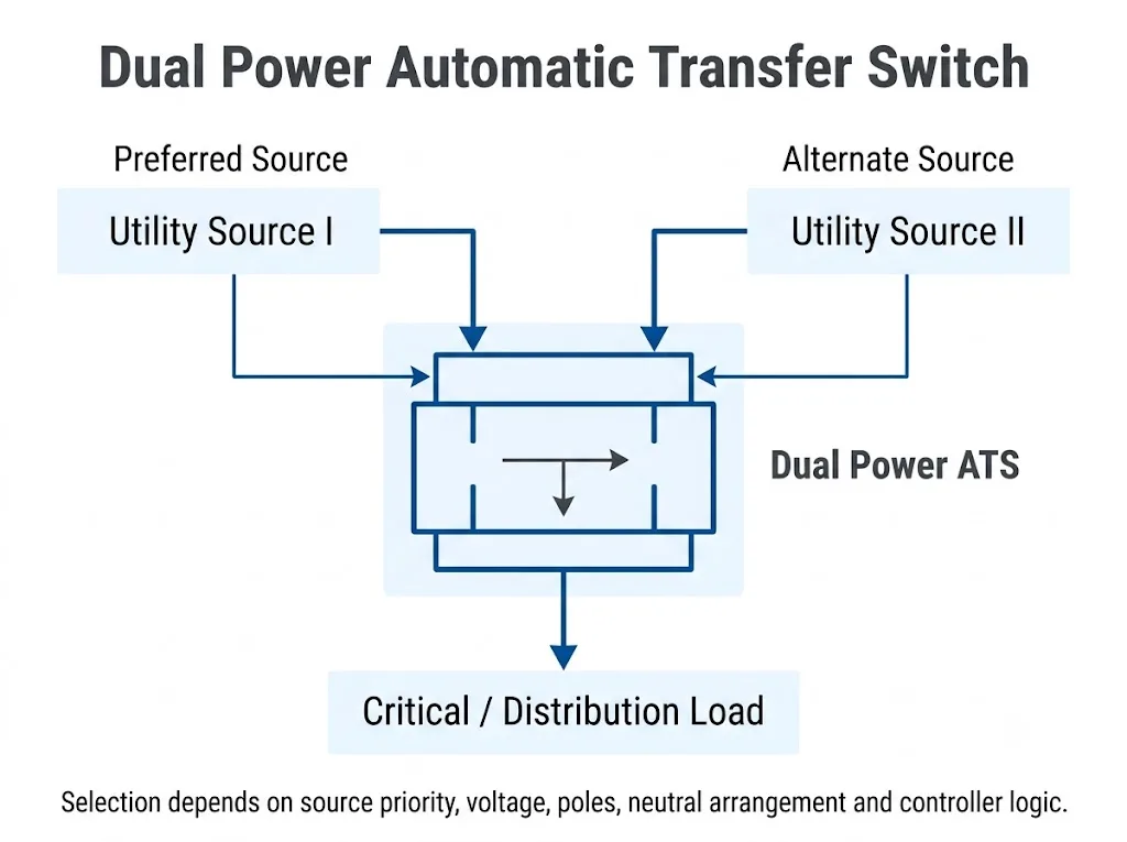
Utility–Utility: Define Source Priority and Return Logic
In a utility–utility arrangement, both incoming sources may already be energized. The project should therefore define which source is preferred, what voltage or frequency conditions make it unacceptable, whether a transfer delay is required and whether the load should automatically return after the preferred source becomes acceptable again.
Available priority modes and monitoring functions depend on the selected controller. They must be checked in the actual ATS/controller documentation rather than assumed from the words “dual power.”
Utility–Generator: Confirm the Generator Interface and Transfer Sequence
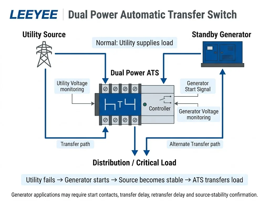
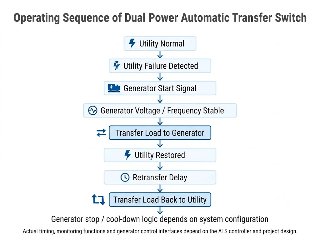
A utility–generator system normally involves more than switching the power contacts. Depending on the controller and generator system, the sequence can include utility-failure detection, a generator-start command, source-acceptance checks, transfer delay, retransfer delay and generator stop or cool-down logic.[5]
Do not assume every automatic transfer switch provides every generator-control function. Confirm the controller outputs, generator-start interface, sensing functions, timers and generator-controller requirements before approving the model.
How Do You Choose 2P, 3P or 4P?
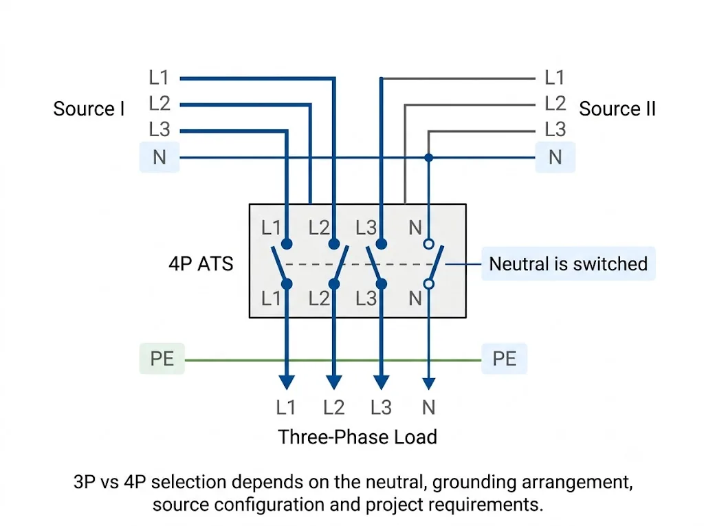
Pole count should follow the conductors that must be transferred. It should not be selected from phase count alone.
| Configuração | Typical Interpretation | O que o Comprador Deve Confirmar |
|---|---|---|
| 2P | Commonly used where two conductors of a single-phase circuit are transferred | Whether neutral must be switched and what the approved project wiring requires |
| 3P | Three phase conductors are switched while neutral, if present, remains outside the transfer poles | Whether a solid neutral is suitable for the source and grounding arrangement |
| 4P | Three phase conductors and neutral are switched | Whether switched neutral is required by the source, grounding design and project rules |
ASCO's transfer-switch guidance distinguishes solid and switched neutral configurations and explains that selection depends on the electrical distribution and whether the alternative source uses a separately derived ground.[2] That is why a simple rule such as “three phase always means 4P” is not technically reliable.
Rated Current Matters, but It Is Not the Whole ATS Specification
The ATS rated current must suit the circuit design, but increasing the ampere rating does not correct an unsuitable source arrangement, pole configuration, controller or short-circuit coordination strategy.
For procurement, confirm the rated operational voltage, frequency, current, load duty and the manufacturer's short-circuit performance data together with the upstream protective device and available fault level. These items need to be evaluated as a system rather than as isolated catalogue numbers.[3]
PC Class or CB Class: Why Does It Matter?
IEC-based transfer-switch projects may distinguish between different equipment classes and short-circuit performance arrangements. ABB's ATS selection guidance discusses Class PC and Class CB architectures as part of ATS selection and short-circuit performance evaluation.[3]
For the buyer, the practical question is not simply “Which class is better?” It is how the switching equipment, upstream protective device and available fault level are coordinated for the actual panel.
If the tender, single-line diagram or panel specification already defines PC Class or CB Class, follow that requirement and verify the selected model accordingly. If it does not, provide the supplier with the protection arrangement and project fault information for technical review.
Which Controller Functions Should You Confirm?
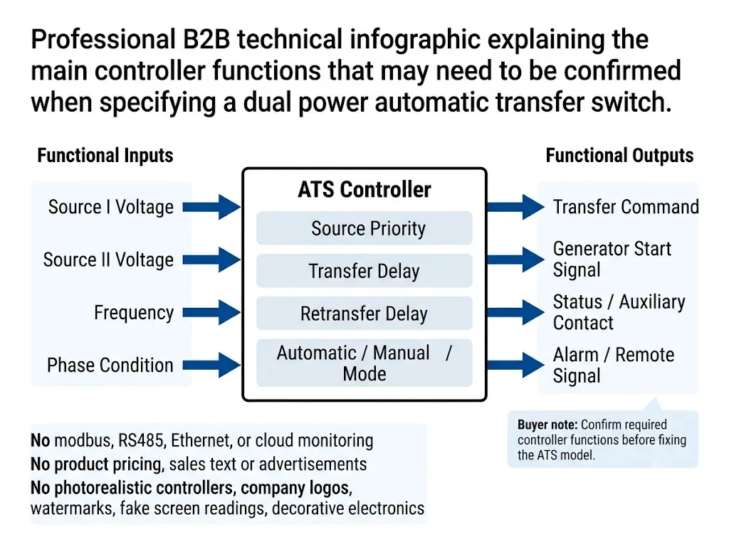
The controller determines much of the real behaviour of a dual power automatic transfer switch. Depending on the selected model, relevant functions can include source-voltage monitoring, frequency monitoring, phase-condition monitoring, source priority, transfer delay, retransfer delay, generator-start output, status contacts, alarm outputs and remote-control functions.
These are procurement items to confirm, not a statement that every compact LEEYEE ATS includes every function. Check the exact controller datasheet and I/O list before fixing the model, particularly where a tender requires generator control, remote indication, communication or a specific source-return sequence.
What Does a Typical Utility–Generator Transfer Sequence Look Like?
A typical utility–generator application can move through source-failure detection, generator start, source acceptance, load transfer, utility return, retransfer and generator stop or cool-down. The actual sequence and timer values are not universal and should be taken from the selected ATS controller and generator documentation.[5]
Automatic Mode and Manual Operation Are Different Requirements
Compact dual-power ATS products may provide both automatic operation and a local manual operating method. These two functions should be evaluated separately.
Automatic mode allows the controller to evaluate source conditions and execute the configured transfer sequence. Manual operation provides a local method of operating the switching mechanism, but the permitted procedure and operating conditions depend on the specific ATS design.
For procurement, ask two separate questions: What does the ATS perform automatically? e How is the switching mechanism operated locally when automatic control is intentionally unavailable?
Do not assume that an “Auto/Manual” marking defines the complete electrical-isolation or maintenance procedure. Those procedures must follow the equipment documentation and the approved project safety rules.
Common Ordering Mistakes That Lead to the Wrong ATS
| Incomplete Request | What Is Missing | Abordagem melhor |
|---|---|---|
| “Need 400 A ATS” | Source pair, voltage, poles, neutral, load duty and controller logic | Send the full electrical and source configuration |
| “Three phase, so 4P” | Neutral and grounding decision | Provide the single-line diagram and earthing arrangement |
| “Generator ATS; automatic is enough” | Generator-start interface, sensing and transfer/retransfer logic | Define the required generator operating sequence |
| “IEC compliant” | Standard edition, exact model and required certificate/report scope | State the project requirement and required evidence |
Which Standards and Documents Should a B2B Buyer Verify?
IEC published IEC 60947-6-1:2026, Edição 4.0 on 2 April 2026. It applies to transfer switching equipment for transferring a load between power supply sources and covers ATSE, including the controller, as well as stand-alone ATS controllers and several defined transfer-switch variants.[1]
The 2026 fourth edition cancels and replaces the third edition published in 2021.[1] However, publication of a new IEC edition does not mean that every existing product, certificate or project specification automatically moves to the new edition.
For project approval, verify the exact model designation, rating, applicable standard edition and the scope of any certificate or test report. If a tender or approved drawing cites a specific edition, confirm the contractual requirement before substituting another edition.
For North American projects, UL Solutions lists multiple transfer-switch categories evaluated to UL 1008, including automatic transfer switches for emergency systems, automatic transfer switches for optional standby systems and nonautomatic transfer switches.[4] The required listing and installation rules should therefore be checked for the actual application rather than inferred from IEC documentation.
A Practical Dual Power ATS Selection Sequence
- Define Source I and Source II. Identify whether each source is utility, generator or another approved AC source.
- Define source priority. State which source normally supplies the load and what should happen after it returns.
- Confirm voltage, frequency and phase. Use the actual project electrical system.
- Confirm neutral treatment. Decide solid or switched neutral from the approved source and grounding arrangement.
- Confirm 2P, 3P or 4P. Pole count follows the conductors that must be transferred.
- Confirm current and load duty. Include motor or high-inrush information where relevant.
- Confirm ATS class and short-circuit coordination. Check the upstream protective device and available fault information.
- Define controller functions. Include only the priority, timers, generator interface, status contacts and remote signals required by the project and supported by the selected model.
- Verify project documents. Confirm the exact model, standard and evidence required before final approval.
Dual Power ATS RFQ Checklist
Send these details before requesting a final model recommendation. A complete RFQ makes quotations easier to compare on the same technical basis.
- Source I type
- Source II type
- Preferred source / priority logic
- Rated system voltage
- Frequência
- Monofásico ou trifásico
- Design / load current
- Requisito de 2P / 3P / 4P
- Disposição do neutro e da ligação à terra
- Informações sobre o tipo de carga e a corrente de arranque
- PC Class / CB Class requirement if specified
- Transfer and retransfer logic
- Generator-start interface if required
- Auxiliary contacts / remote signals if required
- Dispositivo de proteção a montante
- Available fault information where required
- Applicable standard and documents
- Quantidade
- Requisito de etiqueta OEM
- OEM packaging requirement
Need help confirming the dual-power ATS configuration?
Send the two source types, system voltage, current, phase, pole requirement, neutral arrangement, load type and required control logic. LEEYEE can review the configuration information before model confirmation.
Perguntas Frequentes sobre Aquisição
Is a dual power automatic transfer switch different from a normal ATS?
Not necessarily. “Dual power ATS” is commonly used to emphasize that the load can transfer between two power sources. The name alone does not define poles, current, neutral arrangement, ATS class or controller functions.
Can the same ATS be used for utility–utility and utility–generator systems?
Possibly, but this should not be assumed. The power-switching device may be suitable while the controller or I/O configuration is not. A utility–generator application can require generator-start control, source-acceptance logic and timer functions that are unnecessary in a basic utility–utility arrangement.
Should a three-phase dual power ATS be 3P or 4P?
There is no universal answer based only on the words “three phase.” The decision depends on whether neutral must be switched and on the source, grounding and neutral arrangement of the project.[2]
Does every compact ATS support all controller functions listed in this guide?
No. Monitoring, timing, generator control, auxiliary contacts, alarms, communication and remote functions depend on the exact ATS and controller configuration. Confirm them from the selected model documentation before ordering.
Does a dual power ATS automatically start a generator?
Only when the selected ATS/controller and generator-control system provide and use the required interface. Confirm the generator-start contact or control signal, source sensing and controller logic for the exact equipment.
Can a dual power ATS also be operated manually?
Many compact ATS designs provide a manual operating method. The permitted procedure and operating conditions still depend on the specific model and manufacturer instructions.
Is a higher-current ATS always a safer choice?
No. The current rating must suit the circuit, but a larger ampere rating does not correct the wrong neutral treatment, controller logic, load duty or protection coordination.
What is the difference between PC Class and CB Class ATS?
The classes relate to transfer-switch architecture and short-circuit/protection arrangements. Do not identify the class from product appearance alone. Verify the selected model documentation and evaluate it with the upstream protective device, fault level and project specification.[3]
What information is required for an accurate dual power ATS quotation?
Send the two source types, voltage, frequency, phase, design current, neutral and earthing arrangement, poles, load type, source priority, required controller functions, protection information, project documents, quantity and OEM requirements.
Turn your two-source requirement into a model-ready specification
A clear specification reduces technical back-and-forth and makes supplier quotations easier to compare. Share the project parameters when you are ready to confirm the ATS configuration.
Referências
- IEC. IEC 60947-6-1:2026 — Aparelhagem de baixa tensão — Parte 6-1: Equipamentos multifuncionais — Equipamentos de comutação de transferência. Edition 4.0, published 2 April 2026. Página de publicação oficial da IEC.
- Schneider Electric / ASCO Power Technologies. Configurações do neutro em comutadores de transferência. Data Bulletin ASC-DB-NCTS, Version 1.0, 2 August 2024. Official Schneider Electric / ASCO document page.
- ABB. Como selecionar uma classe de comutador de transferência automática. Technical White Paper, document 1SCC303022C0201. Documento técnico da ABB.
- Soluções UL. Serviços de certificação e avaliação de comutadores. Includes transfer-switch categories evaluated to UL 1008. Official UL Solutions page.
- Schneider Electric / ASCO Power Technologies. Timing Delays for ATS Transition Modes. White Paper ASC-TS-WP-123-TD-ATS, 13 October 2020. Official Schneider Electric / ASCO document page.
