
O comprimento do cabo SPD afeta diretamente a proteção fornecida dentro de um quadro de distribuição completo. Um dispositivo de proteção contra surtos pode ter um Up declarado baixo, mas longas conexões podem adicionar tensão indutiva e expor equipamentos a jusante a uma tensão mais alta do que a sugerida apenas pela ficha técnica do SPD.
Mantenha o caminho de conexão completo do SPD o mais curto e direto possível. A regra comumente referenciada A regra de 0,5 m se aplica à fiação total relevante entre os pontos de conexão do conjunto de SPD,, não automaticamente a cada condutor individual.
Quando um fusível ou disjuntor de backup separado é instalado, o total pode incluir o condutor da barra coletora ao dispositivo de backup, o condutor do dispositivo de backup ao SPD, e o condutor do SPD ao PE, PEN ou neutro.
Em instalações baseadas na BS 7671, o total não deve preferencialmente exceder 0,5 m e não deve exceder 1,0 m. Outros mercados devem seguir as regras nacionais aplicáveis e as instruções do fabricante do SPD.
Índice
Por que os cabos de conexão SPD devem ser curtos?
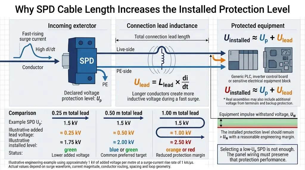
A corrente de surto aumenta muito mais rapidamente do que a corrente de operação normal de 50 Hz ou 60 Hz. A esta alta taxa de variação, a indutância dos condutores de conexão gera tensão adicional.
Uma aproximação de engenharia comumente usada é de cerca de 1 μH de indutância por metro de condutor. Em um exemplo de corrente de surto de 8/20 μs, isso pode corresponder a aproximadamente 1 kV de tensão adicional por metro de cabo de conexão.
A tensão adicional real depende da magnitude do surto, forma de onda, trajeto do condutor, espaçamento do condutor, área do loop, terminais e montagem completa do SPD. Não é correto afirmar que cada metro sempre adiciona exatamente 1 kV.
Caminho mais longo
Uma conexão mais longa geralmente tem mais indutância e, portanto, produz mais tensão adicional durante um surto rápido.
Área do loop maior
Condutores posicionados muito distantes ou ao redor de grandes laços de gabinete podem aumentar ainda mais o efeito da instalação.
Cabo mais grosso não é suficiente
A seção transversal correta é necessária, mas um cabo mais grosso não remove o efeito indutivo de um trajeto desnecessariamente longo.
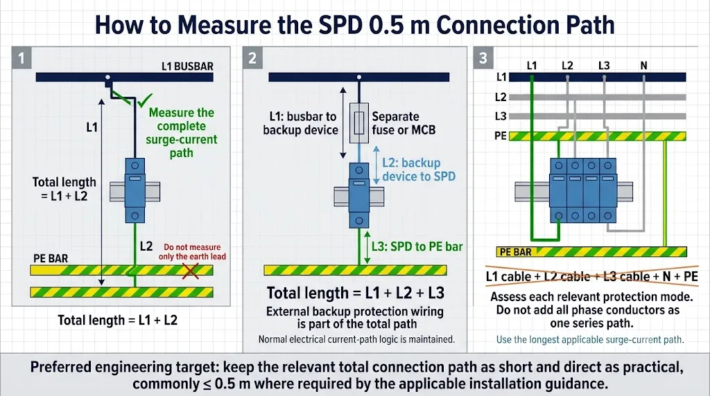
Como é medida a comprimento da conexão SPD de 0,5 m?
As seções exatas dos condutores dependem da disposição de conexão do SPD. No diagrama abaixo, L1, L2 e L3 identificam seções de condutores..Elas não representam as três fases elétricas.
Sem um Dispositivo de Backup SPD Separado
Onde o fabricante do SPD permite que o dispositivo de proteção a montante forneça a proteção de backup necessária, pode não haver uma seção L1 separada. O total relevante pode, portanto, ser:
Barramento ou ponto de ramificação para SPD + SPD para PE, PEN ou neutro.
Com um Fusível ou Disjuntor de Backup Separado
Onde um dispositivo de proteção de backup dedicado é necessário, todas as seções de conexão aplicáveis devem ser consideradas:
Barramento para dispositivo de backup + dispositivo de backup para SPD + SPD para PE, PEN ou neutro.
Painéis Trifásicos
Não some os comprimentos físicos de todos os três condutores de fase como se fossem um único cabo contínuo. Avalie o caminho de proteção aplicável para cada modo e use a rota mais longa relevante.
Não meça a distância em linha reta entre as carcaças dos dispositivos. Siga a rota real do cabo através de terminais, proteção de backup e dutos de fios.
 Abrir Imagem em Tamanho Real
Exemplo de comprimento de cabo SPD trabalhado
Um SPD Tipo 2 está instalado ao lado de um MCB de backup dedicado. O barramento PE está localizado abaixo do SPD.
Medida do Painel Concluída
Os mesmos componentes podem não atender à meta se o disjuntor de backup for movido para outra seção de trilho DIN ou se o condutor PE for roteado através de todo o gabinete. É por isso que a posição do SPD deve ser decidida durante a disposição do painel - não depois que os componentes restantes já tenham sido colocados.
Como o comprimento do cabo altera o nível de proteção instalado?
Para cima é o nível de proteção de tensão declarado para o SPD sob condições de teste definidas. O equipamento a montante pode ver uma tensão mais alta após a inclusão dos efeitos de conexão.
| Comprimento Total da Conexão | Tensão Adicional Ilustrativa | Exemplo com SPD Up = 1,5 kV | Interpretação do Painel |
|---|---|---|---|
| 0,25 m | Aproximadamente 0,25 kV | Aproximadamente 1,75 kV | Conexão curta com uma penalidade de instalação menor. |
| 0,50 m | Aproximadamente 0,50 kV | Aproximadamente 2,00 kV | Meta comum de comprimento deConexão preferencial. |
| 1,00 m | Aproximadamente 1,00 kV | Aproximadamente 2,50 kV | A margem de proteção pode ser significativamente reduzida. |
A tabela utiliza uma aproximação ilustrativa de cerca de 1 kV por metro. Não se trata de um produto garantido ou de um cálculo de desempenho em campo.
 Abrir Imagem em Tamanho Real
Não pergunte apenas, “O que é o SPD Up?” Pergunte, “Qual nível de proteção o SPD selecionado e o arranjo proposto de conexão do painel fornecerão juntos?”
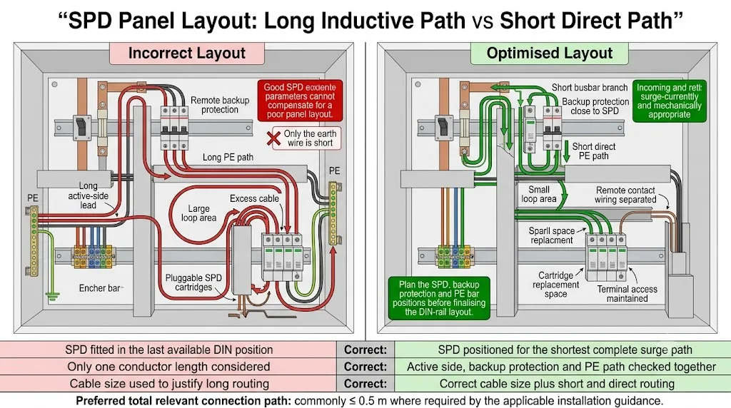
Como um SPD deve ser posicionado dentro de um quadro de distribuição?
O SPD, dispositivo de proteção de backup e conexão de PE devem ser planejados como uma única montagem funcional. Instalar o SPD na última posição disponível do trilho DIN muitas vezes cria um caminho de conexão ruim.
Identifique o Ponto de Conexão Protegido
Confirme onde o ramo do SPD deixará o condutor de entrada, barra coletora ou terminal de distribuição.
Posicione o Dispositivo de Backup ao Lado do SPD
Onde a proteção de backup dedicada é necessária, um fusível remoto ou disjuntor pode consumir a maior parte do comprimento de conexão permitido.
Mantenha o Caminho de PE Curto e Direto
Coloque o SPD próximo a uma conexão apropriada de PE, PEN ou aterramento ao invés de conduzir o condutor através do gabinete.
Evite Laços e Rotas Desnecessárias de Canal de Fiação
Não armazene cabo em excesso ao lado do SPD. Corte os condutores para o comprimento exigido e minimize a área cercada pelo caminho de corrente de surto.
Reserve Espaço de Manutenção
Mantenha o indicador, terminais, contato remoto e cartucho plugável acessíveis após a fiação ser concluída.
 Abrir Imagem em Tamanho Real
E se a conexão SPD não puder ser mantida dentro de 0,5 m?
Não tente resolver um caminho de conexão excessivo apenas aumentando a seção transversal do cabo. Revise primeiro o arranjo físico.
Reposicione o SPD
Mova o SPD mais perto tanto da barra coletora protegida quanto da conexão PE, PEN ou neutra relevante.
Mova a Proteção de Backup
Coloque o fusível ou disjuntor dedicado diretamente ao lado do SPD onde as instruções do produto permitirem.
Use uma Conexão V-Permitida
Uma conexão do tipo V adequada ou uma conexão de passagem pode reduzir o efeito de condutores de ramificação longos, mas apenas quando os terminais do SPD e as instruções do fabricante o permitirem.
Use uma Montagem Integrada
Um SPD com proteção de backup integrada pode remover seções externas de condutores e simplificar a conformidade com o alvo de comprimento de conexão.
Não remova a proteção de backup requerida, exceda as classificações de corrente dos terminais ou trate um SPD paralelo normal como um dispositivo em série de carga total apenas para encurtar a fiação.
Lista de verificação de confirmação para montadores de painéis e OEMs
O comprimento da conexão deve ser considerado antes do desenho do painel e da lista de materiais serem liberados.
Por favor, confirme a largura do módulo SPD, a necessidade de proteção de backup, a capacidade do condutor do terminal, o arranjo de conexão permitido e o desenho de instalação. Nosso alvo para o painel é um caminho de conexão SPD completo dentro de 0,5 m.
Perguntas mais frequentes
Todo condutor do SPD deve ser mais curto do que 0,5 m?
Não. O valor comumente referenciado de 0,5 m normalmente diz respeito ao caminho de conexão total aplicável entre os pontos de conexão da montagem do SPD.
Somente o cabo de aterramento do SPD está incluído na medição?
Não. O condutor do lado ativo e a fiação através de um dispositivo de proteção de backup separado também podem fazer parte do caminho total.
Um cabo mais grosso pode compensar uma conexão de SPD longa?
Não completamente. O tamanho correto do condutor é necessário, mas aumentar a seção transversal não remove o efeito indutivo de comprimento e área de laço excessivos.
Os comprimentos dos três condutores de fase devem ser somados?
Normalmente não. Os três condutores de fase são geralmente caminhos paralelos alternativos, não um caminho contínuo em série. Verifique cada modo de proteção aplicável e use o caminho relevante mais longo.
O que acontece se o caminho de conexão total for 1 m?
A tensão induzida pela conexão pode aumentar significativamente o nível de proteção instalado. Em instalações baseadas na BS 7671, 1 m é declarado como o limite externo em vez da meta de design preferida.
Qual é a diferença entre a regra de 0,5 m e a regra de 10 m?
A orientação de 0,5 m refere-se ao próprio caminho de conexão do SPD. O conceito separado de 10 m refere-se à distância entre um SPD e equipamentos remotos ou outro ponto de distribuição, onde proteção coordenada adicional pode precisar ser avaliada.
Guias técnicos relacionados ao SPD
Referências técnicas
- IEC 60364-5-53:2019+AMD1:2020+AMD2:2024, instalações elétricas de baixa tensão e seleção e instalação de equipamentos elétricos. Página de publicação oficial da IEC .
- IEC 61643-11:2025, dispositivos de proteção contra surtos conectados a sistemas elétricos de baixa tensão - requisitos e métodos de teste. Página de publicação oficial da IEC .
- IET, BS 7671:2018 Webinar de Desmistificação Q&A, explicação do comprimento preferido do condutor de 0,5 m e máximo de 1,0 m. Ver documento do IET .
- Guia de Instalação Elétrica, Conexão do Dispositivo de Proteção Contra Sobretensão, incluindo comprimento total da conexão, indutância do cabo e nível de proteção instalado. Ver guia técnico .
- Mersen, Soluções de Proteção Contra Sobretensão, orientação sobre o efeito de comprimentos de cabo SPD mais longos no desempenho de clamping. Ver orientação da Mersen .
Precisa confirmar um layout de SPD para o seu painel?
Envie o desenho do painel, tensão do sistema, arranjo de aterramento, posição do SPD, arranjo de proteção de backup e posição da barra PE. A LEEYEE pode ajudar a confirmar a configuração do produto e as informações necessárias para uma cotação OEM ou de projeto.
Este artigo fornece orientações gerais de engenharia e aquisição. A seleção final do SPD, fiação, dimensionamento do condutor, proteção de backup e verificação devem seguir o projeto do projeto, regulamentos nacionais aplicáveis, requisitos de montagem do painel e as instruções específicas do fabricante do SPD.
