
Guia de Painéis de Controle Industriais
A proteção contra surtos de VFD normalmente começa no lado de entrada de energia do inversor de frequência variável, e não na saída do motor PWM. Um SPD tipo 2 corretamente selecionado pode ajudar a limitar transientes induzidos por relâmpago e de comutação que entram no painel de controle. No entanto, não pode resolver todos os problemas de tensão entre o VFD e o motor.
A chave é separar a sobretensão transitória de entrada do PWM repetitivo, ondulação refletida e estresse dV/dt gerados na saída do inversor. Este guia explica onde um SPD normalmente pertence, quando as linhas de controle e comunicação precisam de proteção separada, e o que os construtores de painéis devem confirmar antes de fazer um pedido.
Resposta Rápida
Instale o SPD de potência principal no lado de entrada do painel de controle do VFD ou no lado de entrada do drive. Linhas expostas RS485, Modbus, Ethernet, analógicas e de controle remoto podem exigir SPDs de sinal separados.
Não conecte um SPD AC baseado em MOV padrão diretamente à saída PWM do VFD, a menos que o fabricante do drive e o fabricante do dispositivo de proteção aprovem explicitamente essa aplicação. Problemas de cabo de motor longo e onda refletida normalmente exigem reatores de saída aprovados pelo drive, filtros dV/dt ou filtros de onda senoidal.
Índice
Um VFD precisa de proteção contra surtos?
Nem toda instalação de VFD necessita do mesmo arranjo de proteção. A decisão depende do sistema de energia, exposição a raios, localização do painel, SPDs a montante, fiação de campo conectada e as consequências da falha do drive.
A proteção contra surtos externa é particularmente relevante para estações de bombeamento ao ar livre, sistemas de tratamento de água, equipamentos de mineração, plantas industriais com condutores de energia longos, instalações alimentadas por linhas aéreas e processos onde uma falha no drive causaria um tempo de inatividade caro.
Alguns VFDs incluem MOVs internos ou outros componentes de resistência a transientes. Estes podem melhorar a própria resistência a surtos do equipamento, mas não são automaticamente um substituto para um SPD de nível de painel devidamente selecionado.
MOVs embutidos não respondem à questão toda
Verifique a documentação do VFD. A proteção interna pode apoiar a classificação de resistência do equipamento do drive, enquanto um SPD externo é selecionado para a instalação de entrada, especificação do projeto, corrente de descarga e condições de curto-circuito.
Onde o SPD deve ser instalado em um sistema VFD?
A posição de proteção deve seguir o caminho pelo qual o transiente pode entrar. Para a maioria dos armários de VFD, a primeira prioridade é a conexão de energia de entrada. Condutores de sinal e comunicação externos devem ser avaliados separadamente.
| Ponto de instalação | Principal risco | Decisão típica |
|---|---|---|
| Quadro de distribuição principal | Surto de energia mais alto entrando na instalação | Tipo 1 ou Tipo 1+2 quando exigido pelo projeto de proteção contra raios |
| painel de entrada VFD | transientes residuais de raios e comutação a montante | SPD tipo 2 coordenado com proteção a montante |
| PLC ou fonte de controle | Transiente alcançando a eletrônica de controle de baixa tensão | proteção CA ou CC compatível com a tensão de controle real |
| RS485, Modbus ou I/O de campo | Surto entrando através de cabos de sinal externos | SPD de sinal com interface correspondente próximo ao limite de entrada do cabo |
| saída do motor VFD | PWM, onda refletida e estresse dV/dt | Não use um SPD CA comum por padrão; siga as instruções de ambos os fabricantes |
Deslize horizontalmente para ver a tabela completa.
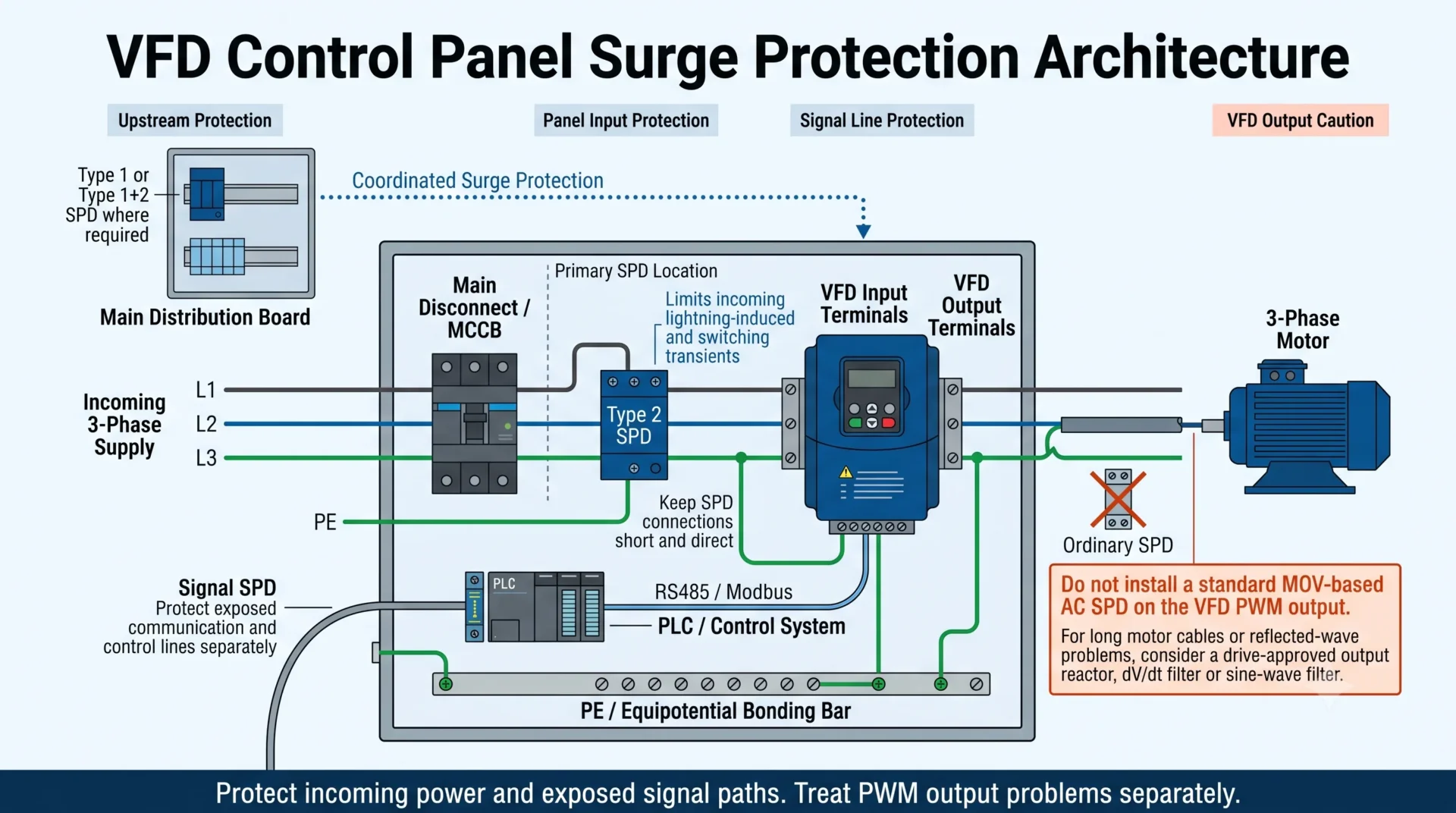
Por que o lado de entrada do VFD é a localização primária para o SPD?
Transientes induzidos por raios, eventos de comutação de utilidade e distúrbios de outras cargas industriais normalmente entram através do fornecimento do VFD. Instalar o SPD antes do inversor ajuda a limitar o transiente antes que ele alcance o retificador de entrada, barramento CC e eletrônica de controle.
Em um gabinete VFD dedicado, o SPD está comumente conectado na entrada do painel ou próximo ao ponto de distribuição de entrada do inversor. A posição exata ainda deve respeitar o roteamento do condutor, layout do invólucro, proteção de backup, corrente de curto-circuito e as instruções de instalação do fabricante do VFD.
Não escolha o SPD apenas com base na classificação em quilowatts ou cavalos-vapor do VFD. O SPD deve corresponder ao sistema elétrico, incluindo tensão de linha a linha, tensão de linha a neutro quando presente, tensão máxima contínua de operação e arranjo de aterramento.
Veja o Guia de Seleção de Uc do SPD para princípios de seleção de tensão.
O que um SPD tipo 2 faz em um painel de controle VFD?
Um SPD tipo 2 é comumente utilizado em nível de distribuição ou painel de controle. Em um VFD gabinete, ele pode ajudar a limitar picos residuais de raios e transientes de comutação que chegam através do fornecimento de entrada.
Um SPD de Tipo 2 selecionado corretamente pode ajudar a proteger:
- O retificador de entrada do VFD e o barramento CC.
- A placa de controle do drive e a fonte de alimentação auxiliar.
- PLCs, HMIs, relés e fontes de alimentação de controle conectados ao mesmo painel.
- O gabinete contra estresse transitório repetido e paradas não planejadas.
Um SPD não é um regulador de voltagem.
Ele é projetado para responder a sobretensões transitórias de curta duração. Não pode manter uma fornecimento instável em uma voltagem fixa ou absorver continuamente uma tensão anômala sustentada.
Surtos de relâmpago, surtos de comutação e estresse PWM do VFD são diferentes
A expressão “pico de voltagem” é frequentemente usada para vários eventos elétricos diferentes. Isso pode levar a decisões de proteção incorretas, pois o mesmo dispositivo não pode resolver todas as formas de sobretensão.
| Perturbação | Fonte típica | Um SPD de entrada pode ajudar? | Outras medidas |
|---|---|---|---|
| Surto induzido por raios | Relâmpago próximo ou um condutor exposto que está chegando | Sim, como parte da proteção contra surtos coordenada. | Tipo 1 ou Tipo 1+2 a montante, onde necessário, aterramento e conexões curtas. |
| Transiente de comutação | Transformador, contator, banco de capacitores ou carga indutiva grande. | Frequentemente sim | Supressão da fonte e projeto de painel correto também podem ser necessários. |
| Sobretensão temporária | Falha de fornecimento, problema de neutro ou voltagem incorreta. | Não como uma solução completa | Corrija a falha e confirme o SPD Uc ou MCOV |
| Pulso de saída PWM | Comutação normal em alta velocidade dentro do VFD | Não | Motor, cabo e projeto de filtro de saída aprovados pelo drive |
| Sobretensão de onda refletida | Cabo de motor longo e desajuste de impedância | Não | Reator de saída, filtro dV/dt ou filtro de onda senoidal |
| EMI de alta frequência | Comutação PWM, acoplamento de cabo e má ligação | Não por si só | Cabo EMC, terminação de blindagem, roteamento e aterramento equipotencial |
Deslize horizontalmente para ver a tabela completa.
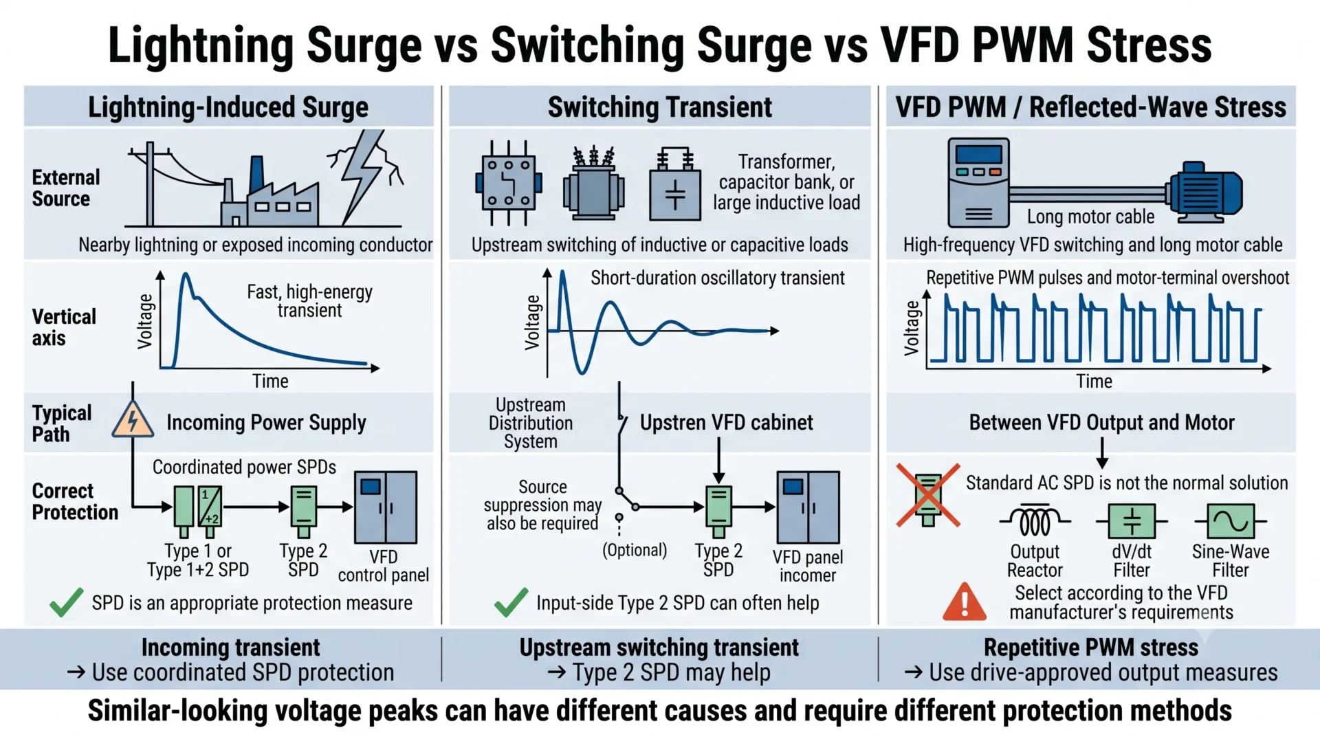
Um SPD pode ser instalado no lado de saída de um VFD?
Não trate a saída do VFD como um suprimento de CA ordinário de 50/60 Hz
A saída de um VFD é uma forma de onda PWM repetitiva e de alta frequência. Um convencional SPD de CA baseado em MOV selecionado para um circuito de distribuição normal pode conduzir repetidamente, superaquecer, envelhecer ou falhar quando exposto a essa forma de onda.
Um SPD Tipo 2 padrão em trilho DIN não deve, portanto, ser conectado diretamente entre as fases de saída do VFD ou entre as fases de saída e a terra.
Produtos especializados podem existir para aplicações específicas de saída de VFD, mas eles não são intercambiáveis com SPDs de distribuição de CA ordinários. Use um produto de proteção do lado de saída apenas quando:
- O fabricante do VFD permite a disposição.
- O fabricante do dispositivo de proteção aprova explicitamente o uso de saída PWM.
- A forma de onda repetitiva e a capacidade de tensão combinam com o inversor.
- O método de instalação está documentado para essa aplicação exata.
O que deve ser usado para cabos de motor longos?
Se o problema for o aumento excessivo nos terminais do motor, alto dV/dt ou onda refletida causada por um cabo longo de VFD para motor, use as medidas recomendadas do fabricante do inversor do lado do motor.
- Reator de saída: adiciona impedância e pode reduzir a severidade da borda de tensão.
- Filtro dV/dt: diminui a borda de tensão PWM e limita o aumento excessivo nos terminais do motor.
- Filtro de onda senoidal: converte a saída mais próxima de uma forma de onda senoidal.
- Cabo de motor classificado VFD: suporta o aterramento correto e caminhos de retorno de alta frequência.
- Motor para inversor: fornece isolamento projetado para o estresse relacionado ao PWM.
Esses dispositivos resolvem um problema diferente de um SPD Tipo 2 de entrada. Algumas instalações requerem tanto proteção contra surtos de entrada quanto filtragem do lado do motor.
As linhas de controle e comunicação do VFD precisam de SPDs de sinal?
Um SPD de potência na entrada do painel não pode proteger contra um transiente que entra através de um condutor de comunicação ou controle de campo separado. A proteção de sinal torna-se mais importante quando os cabos saem do gabinete, conectam equipamentos externos, correm entre edifícios ou passam por diferentes zonas de aterramento.
As interfaces que podem exigir avaliação separada incluem:
- RS485 e Modbus RTU.
- CAN bus e redes seriais industriais.
- Ethernet industrial.
- Controle analógico de 0–10 V.
- Laços de corrente de 4–20 mA.
- Partida remota, parada, alarme e I/O digital.
- Sensores externos de pressão, fluxo, temperatura e nível.
O SPD de sinal deve corresponder à tensão de trabalho, tipo de interface, taxa de transmissão, arranjo de cabeamento e perda de inserção aceitável. Um SPD Tipo 2 da rede elétrica nunca deve ser substituído por um protetor de linha de sinal.
Aterramento, ligação e comprimento de conexão
Mesmo um SPD corretamente selecionado pode fornecer proteção insuficiente se seus condutores de conexão forem longos, em laços ou conectados de forma inadequada. A tensão desenvolvida ao longo dos condutores durante um surto rápido adiciona ao nível de proteção do SPD.
- Mantenha o condutor protegido e as conexões do SPD curtas e diretas.
- Mantenha a conexão do SPD para o PE curta e livre de laços desnecessários.
- Não enrole o comprimento excessivo do condutor.
- Use o painel PE ou a barra de aterramento equipotencial pretendida.
- Evite roteamento paralelo longo de condutores protegidos e não protegidos.
- Separe a fiação de sinal sensível dos cabos de entrada do VFD e da alimentação do motor.
- Termine o aterramento dos cabos do motor de acordo com as instruções de EMC do fabricante do VFD.
Baixo nível de proteção não é suficiente se a fiação for ruim.
O nível de proteção instalado inclui o efeito dos condutores de conexão. Compare o SPD Up com o nível de suportabilidade do equipamento, mas também controle o comprimento, roteamento e aterramento dos condutores.
O que um SPD não pode consertar em uma instalação VFD
Um SPD maior não é uma resposta universal para todas as falhas do drive. Separe os danos transitórios de problemas de qualidade de energia, térmicos, de instalação e do lado do motor.
| Problema | Por que um SPD não é a solução completa | O que investigar |
|---|---|---|
| Harmônicos | Um SPD não remodela a corrente nem corrige a distorção harmônica | Reator de linha, filtro passivo, filtro ativo ou acionamento de baixa harmônica |
| Sobretensão sustentada | Um SPD é projetado para transientes, não para tensão anormal contínua | Transformador, neutro, tensão do sistema e Uc ou MCOV |
| Estresse dV/dt do motor | O estresse é produzido pela comutação PWM repetitiva | Cabo do motor, comprimento do cabo, reator de saída ou filtro |
| Corrente de rolamento | Está relacionado à tensão de modo comum e a caminhos de corrente de alta frequência | Aterramento, aterramento do eixo, rolamentos isolados e design de filtro |
| Superaquecimento | Um SPD não pode corrigir o fluxo de ar bloqueado ou a temperatura excessiva do gabinete | Ventilação, desclassificação, filtros, ventiladores e design de invólucro |
| Parâmetros de VFD incorretos | Um SPD não pode corrigir configurações inadequadas de aceleração, motor ou controle | Comissionamento do acionamento e dados da placa de identificação do motor |
Deslize horizontalmente para ver a tabela completa.
Como selecionar um SPD para um painel de controle VFD
Não selecione o SPD apenas com base na “aplicação de VFD”. O VFD é a carga protegida, mas o SPD deve primeiro corresponder ao sistema elétrico no qual o painel está instalado.
| Informações para confirmação | Por que isso importa | Consequência de seleção |
|---|---|---|
| Tensão nominal de entrada | Define a tensão normal na localização do SPD | Determina a faixa básica de Uc ou MCOV |
| Tensão contínua máxima | Fornecimentos industriais podem operar acima de seu valor nominal | Prevenção da seleção de Uc ou MCOV muito baixos |
| Fonte de três fios ou quatro fios | O VFD pode não usar neutro, enquanto os controles do painel ainda podem | Determina a contagem de pólos e modos de proteção |
| Sistema TN, TT, IT ou delta | A aterramento altera a tensão linha-terra e os modos requeridos | Determina se 3P, 4P, 3+1 ou outro arranjo é adequado |
| Exposição a raios | Sistemas externos e aéreos podem enfrentar uma corrente de surto maior | Influencia a coordenação Tipo 1 e Tipo 2 |
| SPD a montante | O SPD do painel deve coordenar com o serviço ou o quadro principal | Prevenir que cada SPD seja selecionado como um dispositivo isolado |
| Corrente de curto-circuito | O painel pode ter uma alta corrente de falha disponível | Confirma os requisitos da SCCR e do fusível ou disjuntor de backup |
| Up ou VPR requeridos | A tensão residual deve atender ao equipamento protegido | Confirma o nível de proteção efetivo |
| Interfaces de controle | Condutores de potência e sinal requerem proteção diferente | Identifica as necessidades de SPD de RS485, Ethernet, sinal analógico ou digital |
| Norma exigida | Projetos IEC e UL utilizam sistemas de marcação e listagem diferentes | Determina a gama de produtos e documentação elegíveis |
| Requisito de alarme remoto | As equipes de manutenção podem precisar monitorar a condição do SPD | Determina se é necessário um contacto remoto NA/NF |
Deslize horizontalmente para ver a tabela completa.
Painéis VFD de 400 V e 480 V não são automaticamente iguais
Um painel IEC de 400 V e um painel norte-americano de 480 V podem exigir diferentes tensões nominais de SPD, modos de proteção, normas e coordenação de curto-circuito. Não os trate como intercambiáveis apenas porque ambos são sistemas trifásicos.
Não escolha automaticamente o Uc mais elevado
Um Uc mais elevado pode melhorar a tolerância à tensão contínua do sistema, mas também pode resultar num nível de proteção mais elevado. A seleção deve equilibrar o funcionamento estável com a resistência ao impulso do VFD e do equipamento de controlo próximo.
Direção de proteção LEEYEE para painéis VFD
A tabela seguinte é uma orientação de seleção e não substitui a verificação do sistema elétrico. Um modelo específico só deve ser confirmado após a revisão da tensão, esquema de ligação à terra, proteção de reserva, layout do quadro e norma do projeto.
| Ponto de proteção | Orientação de produtos LEEYEE | O comprador deve confirmar |
|---|---|---|
| Alimentação AC de entrada de VFD |
SPD Tipo 2 para calha DIN AC
Ver orientação de SPD Tipo 2 |
Tensão, sistema de ligação à terra, polos, Uc, Up, In, Imax e proteção de reserva |
| Quadro de entrada de maior exposição |
SPD Tipo 1+2 para calha DIN quando o projeto exige capacidade de corrente de relâmpago
Ver orientação de SPD Tipo 1+2 |
Proteção externa contra relâmpagos, alimentação aérea, SPD a montante e Iimp necessário |
| Linha RS485 ou Modbus |
SPD de sinal compatível com a interface
Verificar requisitos de proteção RS485 |
Tensão de sinal, cablagem, taxa de transmissão, blindagem, ligação à terra e limite de instalação |
| Monitorização do estado do SPD |
SPD de potência com contacto de alarme remoto onde a monitorização é necessária
Verificar cablagem de contacto remoto do PLC |
Lógica NA/NF, tensão de entrada digital do PLC e estratégia de alarme à prova de falhas |
| saída do motor VFD | Nenhuma recomendação de SPD AC padrão | Aprovação do fabricante do inversor, compatibilidade PWM, comprimento do cabo do motor e requisitos de filtro de saída |
Deslize horizontalmente para ver a tabela completa.
Não selecione com base apenas na potência nominal do VFD
Um VFD de 30 kW e um de 75 kW ligados ao mesmo sistema elétrico podem utilizar a mesma configuração de SPD de entrada. A tensão do sistema, a ligação à terra, a corrente de defeito e o nível de proteção necessário são normalmente mais importantes do que a potência nominal do motor.
Cenários típicos de proteção de painéis VFD
Armário interior de 400 V
Um SPD Tipo 2 no entrada do armário pode ser adequado quando coordenado com o quadro a montante. Confirme o esquema TN ou TT e se o neutro é utilizado.
Estação de bombagem exterior
Avalie a proteção Tipo 1 ou Tipo 1+2 a montante, proteção Tipo 2 local, linhas de sensores remotos, linhas de comunicação e equipotencialidade do armário.
MCC de três fios de 480 V
Selecione a proteção para o esquema real de três fios e ligação à terra. Não especifique um SPD de quatro polos apenas porque o sistema é trifásico.
Informações para confirmar antes de solicitar um SPD para o painel VFD
Fornecer as informações seguintes permite ao fornecedor recomendar uma configuração adequada em vez de adivinhar com base numa fotografia do armário ou na potência nominal do VFD.
- Tensão de entrada do VFD e gama de funcionamento.
- Frequência do sistema.
- Alimentação trifásica ou tetrafásica.
- Sistema TN-S, TN-C-S, TT, IT ou delta.
- Sistema externo de proteção contra descargas atmosféricas.
- Alimentação de entrada aérea ou subterrânea.
- Tipo de SPD a montante e ponto de instalação.
- Corrente de curto-circuito prospectiva.
- Fusível ou disjuntor de reserva disponível.
- Classificação Tipo 1, Tipo 2 ou Tipo 1+2 necessária.
- Uc, Up, In, Imax ou Iimp necessários.
- Espaço disponível em calha DIN.
- Interfaces RS485, Ethernet, analógicas ou de I/O de campo.
- Requisito de contacto de alarme remoto.
- Documentação IEC, CE, TÜV, UL ou do projeto.
- Quantidade, rotulagem, embalagem e requisitos OEM.
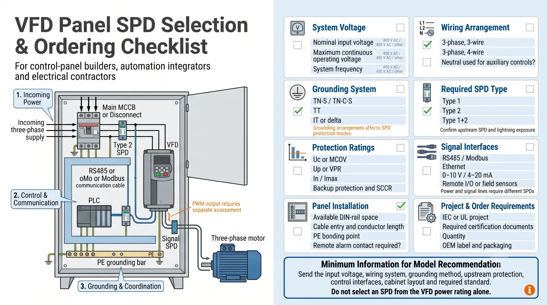
Precisa de ajuda para selecionar um SPD para um painel VFD?
Envie-nos a tensão de entrada do VFD, o esquema de cablagem, o sistema de ligação à terra, a proteção a montante, a disposição do painel e a norma necessária. A LEEYEE pode ajudar a confirmar a direção do SPD de potência de entrada e identificar se deve ser considerada uma proteção de sinal separada.
Perguntas mais frequentes
Todos os VFDs precisam de um SPD externo?
Nem todas as instalações necessitam do mesmo esquema. A decisão depende da exposição a descargas atmosféricas, da alimentação de entrada, da proteção a montante, da cablagem de campo, dos requisitos do projeto e da proteção integrada do fabricante do VFD.
O SPD deve ser instalado antes ou depois do VFD?
Um SPD de distribuição CA normal é geralmente instalado antes do VFD, na entrada do quadro ou na entrada do variador. Não coloque um SPD convencional na saída PWM, a menos que ambos os fabricantes aprovem essa aplicação específica.
Um SPD de Tipo 2 pode proteger um VFD?
Um SPD Tipo 2 corretamente selecionado pode limitar as descargas atmosféricas residuais e os transientes de comutação que entram através da fonte de alimentação. Deve corresponder à tensão, ao sistema de ligação à terra, aos modos de proteção e às condições de curto-circuito.
Posso instalar um SPD normal na saída do VFD?
Normalmente não. A saída do VFD é uma forma de onda PWM repetitiva em vez de uma alimentação de rede sinusoidal comum. Utilize apenas uma solução do lado da saída especificamente aprovada para o VFD e para o ambiente PWM.
Um VFD com MOVs integrados ainda precisa de um SPD externo?
Pode melhorar. Os MOVs integrados podem melhorar a resistência do equipamento, mas podem não cumprir o tipo de SPD, a corrente de descarga, o SCCR, o VPR ou a especificação de monitorização exigidos pela instalação.
Um SPD protege o motor contra dV/dt?
Um SPD de entrada normal não resolve o stress dV/dt ou de onda refletida do lado do motor. Dependendo da aplicação, a solução pode ser um reator de saída, filtro dV/dt, filtro de onda sinusoidal, motor de serviço de inversor ou cabo classificado para VFD.
Deve uma conexão RS485 a um VFD ser protegida?
Considere um SPD RS485 quando o cabo sai do quadro, liga equipamento exterior, percorre uma longa distância ou atravessa edifícios ou zonas de ligação à terra diferentes.
Quão perto o SPD deve ser instalado em relação ao VFD?
Instale-o num ponto de ligação de entrada apropriado e mantenha os condutores do lado da potência e de PE curtos e diretos. Evite laços longos e o encaminhamento paralelo com condutores de entrada desprotegidos.
Qual voltagem de SPD deve ser utilizada para um VFD de 400 V ou 480 V?
Não pode ser selecionado apenas pela tensão nominal. Confirme a tensão contínua máxima, a tensão entre fases e entre fase e terra, a disposição do neutro, o sistema de ligação à terra e os requisitos IEC ou UL aplicáveis.
Um reator de entrada é o mesmo que um SPD?
Não. Um SPD limita a sobretensão transitória de curta duração. Um reator de entrada adiciona impedância e é utilizado para diferentes fins de qualidade de energia e proteção do acionamento.
Notas Técnicas e Âmbito
Este guia aplica-se a painéis de controlo de VFD de baixa tensão e a SPD de potência e sinal de calha DIN convencionais. Não substitui as instruções do fabricante do VFD, a folha de dados do SPD, uma avaliação de risco de descargas atmosféricas ou a norma elétrica local aplicável.
Assume-se que um SPD de CA convencional seja instalado no lado da entrada de energia. Qualquer produto utilizado na saída PWM de um VFD deve ser especificamente concebido e aprovado para esse ambiente. A seleção final deve ser confirmada relativamente à tensão real, sistema de ligação à terra, corrente de defeito, proteção a montante e nível de resistência do equipamento.
