
Industrial Control Panel Guide
VFD surge protection normally starts on the incoming power side of the variable frequency drive, not on its PWM motor output. A correctly selected Type 2 SPD can help limit lightning-induced and switching transients entering the control panel. However, it cannot solve every voltage problem between the VFD and the motor.
The key is to separate incoming transient overvoltage from the repetitive PWM, reflected-wave and dV/dt stress generated on the drive output. This guide explains where an SPD normally belongs, when control and communication lines need separate protection, and what panel builders should confirm before ordering.
Quick Answer
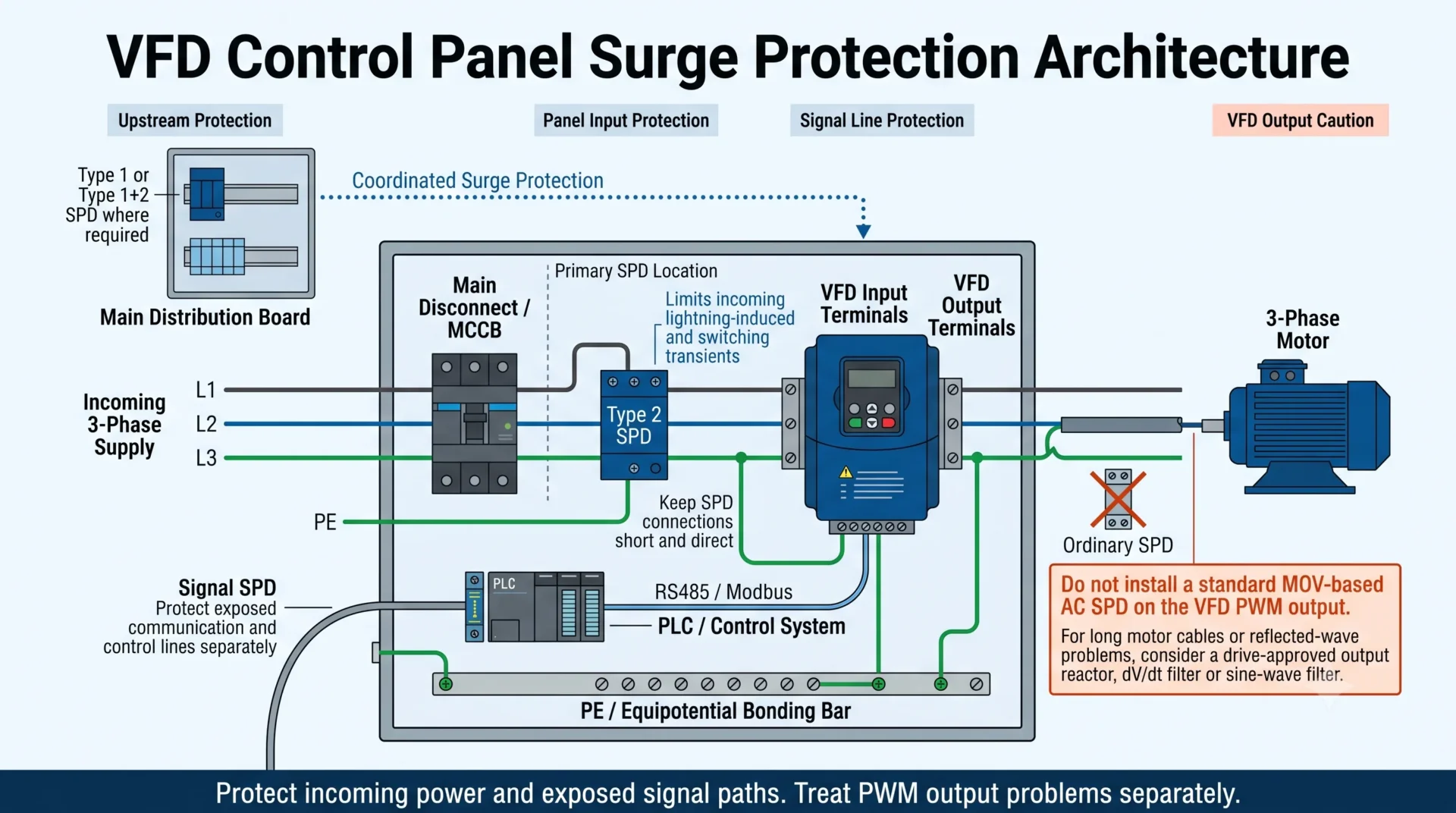
Install the main power SPD at the VFD control-panel incomer or on the incoming side of the drive. Exposed RS485, Modbus, Ethernet, analog and remote-control lines may require separate signal SPDs.
Do not connect a standard MOV-based AC SPD directly to the VFD PWM output unless the drive manufacturer and the protection-device manufacturer explicitly approve that application. Long motor cable and reflected-wave problems normally require drive-approved output reactors, dV/dt filters or sine-wave filters.
Table of Contents
Does a VFD Need Surge Protection?
Not every VFD installation needs the same protection arrangement. The decision depends on the power system, lightning exposure, panel location, upstream SPDs, connected field wiring and the consequences of drive failure.
External surge protection is particularly relevant for outdoor pump stations, water-treatment systems, mining equipment, industrial plants with long power conductors, installations supplied by overhead lines and processes where a failed drive would cause expensive downtime.
Some VFDs include internal MOVs or other transient-withstand components. These can improve the equipment's own surge withstand, but they are not automatically a substitute for a properly selected panel-level SPD.
Built-in MOVs do not answer the whole question
Check the VFD documentation. Internal protection may support the drive's equipment withstand rating, while an external SPD is selected for the incoming installation, project specification, discharge current and short-circuit conditions.
Where Should the SPD Be Installed in a VFD System?
The protection position should follow the path through which the transient can enter. For most VFD cabinets, the first priority is the incoming power connection. External signal and communication conductors must be assessed separately.
| Installation point | Main risk | Typical decision |
|---|---|---|
| Main distribution board | Higher-energy surge entering the installation | Type 1 or Type 1+2 where required by the lightning-protection design |
| VFD panel incomer | Residual lightning and upstream switching transients | Type 2 SPD coordinated with upstream protection |
| PLC or control supply | Transient reaching low-voltage control electronics | AC or DC protection matched to the actual control voltage |
| RS485, Modbus or field I/O | Surge entering through external signal cables | Interface-matched signal SPD near the cable-entry boundary |
| VFD motor output | PWM, reflected-wave and dV/dt stress | Do not use an ordinary AC SPD by default; follow both manufacturers' instructions |
Swipe horizontally to view the complete table.
Why Is the VFD Input Side the Primary SPD Location?
Lightning-induced transients, utility switching events and disturbances from other industrial loads normally enter through the VFD supply. Installing the SPD before the drive helps limit the transient before it reaches the input rectifier, DC bus and control electronics.
In a dedicated VFD cabinet, the SPD is commonly connected at the panel incomer or near the drive input distribution point. The exact position must still respect conductor routing, enclosure layout, backup protection, short-circuit current and the VFD manufacturer's installation instructions.
Do not choose the SPD only from the VFD kilowatt or horsepower rating. The SPD must match the electrical system, including line-to-line voltage, line-to-neutral voltage where present, maximum continuous operating voltage and earthing arrangement.
See the SPD Uc Selection Guide for voltage-selection principles.
What Does a Type 2 SPD Do in a VFD Control Panel?
A Type 2 SPD is commonly used at a distribution or control-panel level. In a VFD cabinet, it can help limit residual lightning surges and switching transients arriving through the incoming supply.
A correctly selected Type 2 SPD can help protect:
- The VFD input rectifier and DC bus.
- The drive control board and auxiliary power supply.
- PLCs, HMIs, relays and control power supplies connected to the same panel.
- The cabinet against repeated transient stress and unplanned downtime.
An SPD is not a voltage regulator
It is designed to respond to short-duration transient overvoltage. It cannot hold an unstable supply at a fixed voltage or continuously absorb a sustained abnormal system voltage.
Lightning Surge, Switching Surge and VFD PWM Stress Are Different
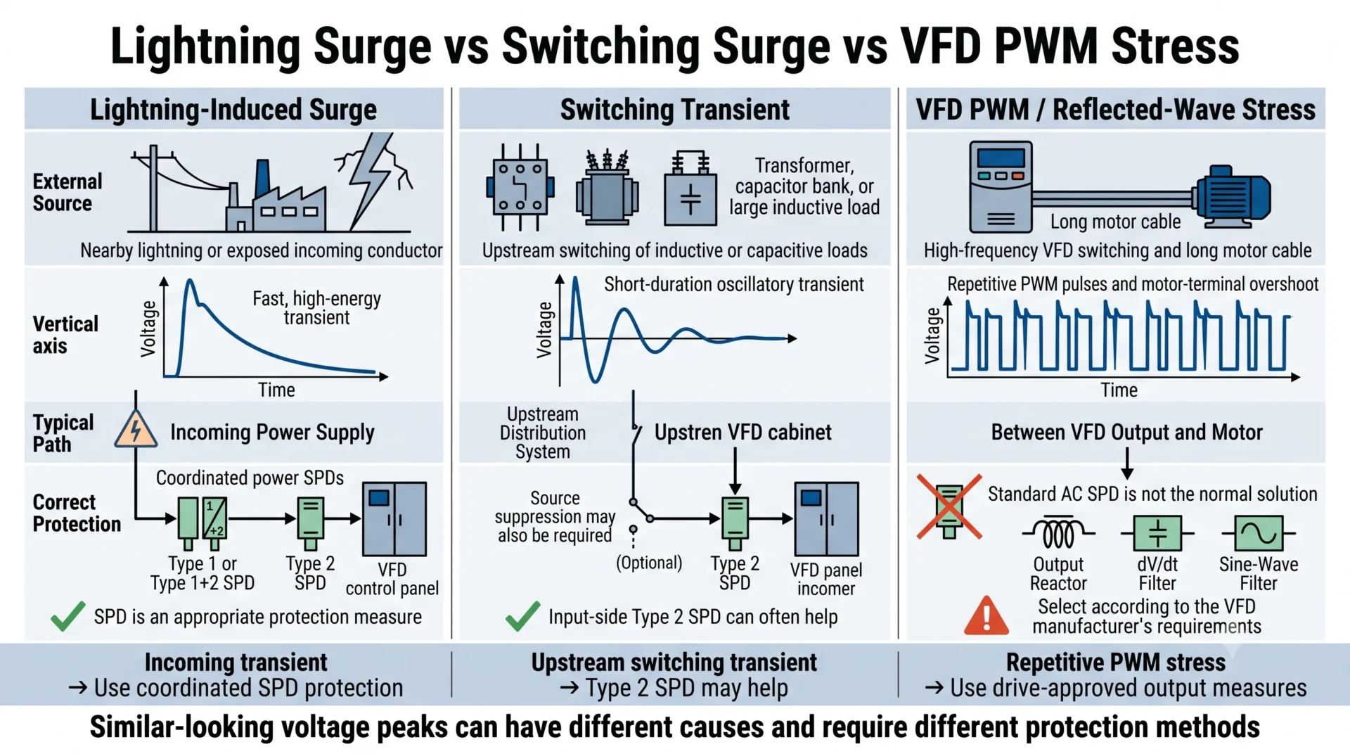
The phrase “voltage spike” is often used for several different electrical events. This can lead to incorrect protection decisions because the same device cannot solve every form of overvoltage.
| Disturbance | Typical source | Can an input SPD help? | Other measures |
|---|---|---|---|
| Lightning-induced surge | Nearby lightning or an exposed incoming conductor | Yes, as part of coordinated surge protection | Upstream Type 1 or Type 1+2 where required, bonding and short connections |
| Switching transient | Transformer, contactor, capacitor bank or large inductive load | Often yes | Source suppression and correct panel design may also be required |
| Temporary overvoltage | Supply fault, neutral problem or incorrect voltage | Not as a complete solution | Correct the fault and confirm the SPD Uc or MCOV |
| PWM output pulse | Normal high-speed switching inside the VFD | No | Drive-approved motor, cable and output-filter design |
| Reflected-wave overvoltage | Long motor cable and impedance mismatch | No | Output reactor, dV/dt filter or sine-wave filter |
| High-frequency EMI | PWM switching, cable coupling and poor bonding | Not by itself | EMC cable, shield termination, routing and equipotential bonding |
Swipe horizontally to view the complete table.
Can an SPD Be Installed on the Output Side of a VFD?
Do not treat the VFD output as an ordinary 50/60 Hz AC supply
A VFD output is a repetitive, high-frequency PWM waveform. A conventional MOV-based AC SPD selected for a normal distribution circuit may repeatedly conduct, overheat, age or fail when exposed to this waveform.
A standard DIN-rail Type 2 SPD should therefore not normally be connected directly between the VFD output phases or between the output phases and earth.
Specialist products may exist for particular VFD output applications, but they are not interchangeable with ordinary AC distribution SPDs. Use an output-side protection product only when:
- The VFD manufacturer permits the arrangement.
- The protection-device manufacturer explicitly approves PWM output use.
- The repetitive waveform and voltage capability match the drive.
- The installation method is documented for that exact application.
What should be used for long motor cables?
If the problem is motor-terminal overshoot, high dV/dt or reflected wave caused by a long VFD-to-motor cable, use the drive manufacturer's recommended motor-side measures.
- Output reactor: adds impedance and can reduce voltage-edge severity.
- dV/dt filter: slows the PWM voltage edge and limits motor-terminal overshoot.
- Sine-wave filter: converts the output closer to a sinusoidal waveform.
- VFD-rated motor cable: supports correct shielding and high-frequency return paths.
- Inverter-duty motor: provides insulation designed for PWM-related stress.
These devices solve a different problem from an incoming Type 2 SPD. Some installations require both input surge protection and motor-side filtering.
Do VFD Control and Communication Lines Need Signal SPDs?
A power SPD at the panel incomer cannot protect a transient entering through a separate communication or field-control conductor. Signal protection becomes more important when cables leave the cabinet, connect outdoor equipment, run between buildings or pass through different grounding zones.
Interfaces that may require separate assessment include:
- RS485 and Modbus RTU.
- CAN bus and industrial serial networks.
- Industrial Ethernet.
- 0–10 V analog control.
- 4–20 mA current loops.
- Remote start, stop, alarm and digital I/O.
- External pressure, flow, temperature and level sensors.
The signal SPD must match the working voltage, interface type, transmission rate, wiring arrangement and acceptable insertion loss. A mains Type 2 SPD must never be substituted for a signal-line protector.
See the RS485 SPD Wiring and Selection Guide .
Grounding, Bonding and Connection Length
Even a correctly selected SPD can provide poor protection if its connecting conductors are long, looped or routed incorrectly. The voltage developed along the conductors during a fast surge adds to the SPD's own protection level.
- Keep the protected-conductor and SPD connections short and direct.
- Keep the SPD-to-PE connection short and free from unnecessary loops.
- Do not coil excess conductor length.
- Use the intended panel PE or equipotential bonding bar.
- Avoid long parallel routing of protected and unprotected conductors.
- Separate sensitive signal wiring from VFD input and motor power cables.
- Terminate motor cable shielding according to the VFD manufacturer's EMC instructions.
Low Up is not enough if the wiring is poor
The installed protection level includes the effect of the connection conductors. Compare the SPD Up with the equipment withstand level, but also control conductor length, routing and bonding.
See the SPD Up Voltage Protection Level Guide .
What an SPD Cannot Fix in a VFD Installation
A larger SPD is not a universal answer to every drive failure. Separate transient damage from power-quality, thermal, installation and motor-side problems.
| Problem | Why an SPD is not the complete solution | What to investigate |
|---|---|---|
| Harmonics | An SPD does not reshape current or correct harmonic distortion | Line reactor, passive filter, active filter or low-harmonic drive |
| Sustained overvoltage | An SPD is designed for transients, not continuous abnormal voltage | Transformer, neutral, system voltage and Uc or MCOV |
| Motor dV/dt stress | The stress is produced by repetitive PWM switching | Motor cable, lead length, output reactor or filter |
| Bearing current | It is related to common-mode voltage and high-frequency current paths | Grounding, shaft grounding, insulated bearings and filter design |
| Overheating | An SPD cannot correct blocked airflow or excessive cabinet temperature | Ventilation, derating, filters, fans and enclosure design |
| Incorrect VFD parameters | An SPD cannot correct unsuitable acceleration, motor or control settings | Drive commissioning and motor nameplate data |
Swipe horizontally to view the complete table.
How to Select an SPD for a VFD Control Panel
Do not select the SPD from “VFD application” alone. The VFD is the protected load, but the SPD must first match the electrical system in which the panel is installed.
| Information to confirm | Why it matters | Selection consequence |
|---|---|---|
| Nominal input voltage | Defines the normal voltage at the SPD location | Determines the basic Uc or MCOV range |
| Maximum continuous voltage | Industrial supplies may operate above their nominal value | Prevents Uc or MCOV from being selected too low |
| Three-wire or four-wire supply | The VFD may not use neutral, while panel controls still might | Determines pole count and protection modes |
| TN, TT, IT or delta system | Earthing changes line-to-earth voltage and required modes | Determines whether 3P, 4P, 3+1 or another arrangement is suitable |
| Lightning exposure | Outdoor and overhead systems may face greater surge current | Influences Type 1 and Type 2 coordination |
| Upstream SPD | The panel SPD must coordinate with the service or main board | Prevents each SPD from being selected as an isolated device |
| Short-circuit current | The panel may have high available fault current | Confirms SCCR and backup fuse or breaker requirements |
| Required Up or VPR | The residual voltage must suit the protected equipment | Confirms the effective protection level |
| Control interfaces | Power and signal conductors require different protection | Identifies RS485, Ethernet, analog or digital signal SPD needs |
| Required standard | IEC and UL projects use different marking and listing systems | Determines the eligible product and documentation range |
| Remote alarm requirement | Maintenance teams may need to monitor SPD condition | Determines whether an NO/NC remote contact is required |
Swipe horizontally to view the complete table.
400 V and 480 V VFD panels are not automatically the same
A 400 V IEC panel and a 480 V North American panel may require different SPD voltage ratings, protection modes, standards and short-circuit coordination. Do not treat them as interchangeable because both are three-phase systems.
Do not automatically choose the highest Uc
A higher Uc can improve tolerance to continuous system voltage, but it may also result in a higher protection level. Selection must balance stable operation with the impulse withstand of the VFD and nearby control equipment.
LEEYEE Protection Direction for VFD Panels
The following table is a selection direction, not a substitute for checking the electrical system. A specific model should only be confirmed after reviewing the voltage, earthing arrangement, backup protection, panel layout and project standard.
| Protection point | LEEYEE product direction | Buyer must confirm |
|---|---|---|
| VFD incoming AC power |
AC Type 2 DIN-rail SPD
View Type 2 SPD direction |
Voltage, earthing system, poles, Uc, Up, In, Imax and backup protection |
| Higher-exposure incoming panel |
Type 1+2 DIN-rail SPD where the project requires lightning-current capability
View Type 1+2 SPD direction |
External lightning protection, overhead supply, upstream SPD and required Iimp |
| RS485 or Modbus line |
Signal SPD matched to the interface
Check RS485 protection requirements |
Signal voltage, wiring, baud rate, shield, grounding and installation boundary |
| SPD status monitoring |
Power SPD with remote alarm contact where monitoring is required
Check PLC remote-contact wiring |
NO/NC logic, PLC digital-input voltage and fail-safe alarm strategy |
| VFD motor output | No standard AC SPD recommendation | Drive manufacturer approval, PWM compatibility, motor cable length and output-filter requirement |
Swipe horizontally to view the complete table.
Do not select from the VFD power rating alone
A 30 kW and a 75 kW VFD connected to the same electrical system may use the same incoming SPD configuration. The system voltage, earthing, fault current and required protection level are normally more important than the motor power rating.
Typical VFD Panel Protection Scenarios
Indoor 400 V Cabinet
A Type 2 SPD at the cabinet incomer may be suitable when coordinated with the upstream board. Confirm TN or TT arrangement and whether neutral is used.
Outdoor Pump Station
Assess upstream Type 1 or Type 1+2 protection, local Type 2 protection, remote sensor lines, communication lines and cabinet bonding.
480 V Three-Wire MCC
Select protection for the actual three-wire and grounding arrangement. Do not specify a four-pole SPD simply because the system is three-phase.
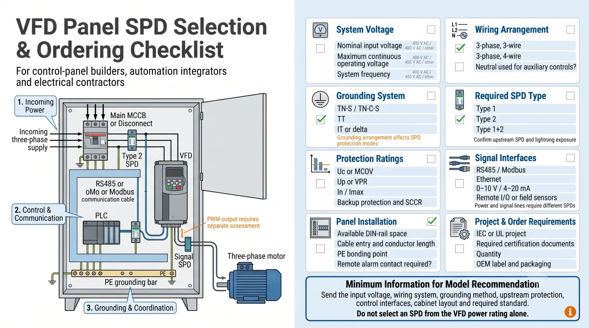
Information to Confirm Before Ordering a VFD Panel SPD
Providing the following information allows the supplier to recommend a suitable configuration instead of guessing from a cabinet photograph or VFD power rating.
- VFD input voltage and operating range.
- System frequency.
- Three-wire or four-wire supply.
- TN-S, TN-C-S, TT, IT or delta system.
- External lightning protection system.
- Overhead or underground incoming supply.
- Upstream SPD type and installation point.
- Prospective short-circuit current.
- Available backup fuse or breaker.
- Required Type 1, Type 2 or Type 1+2 classification.
- Required Uc, Up, In, Imax or Iimp.
- Available DIN-rail space.
- RS485, Ethernet, analog or field-I/O interfaces.
- Remote alarm contact requirement.
- IEC, CE, TÜV, UL or project documentation.
- Quantity, labeling, packaging and OEM requirements.
Need Help Selecting an SPD for a VFD Panel?
Send us the VFD input voltage, wiring arrangement, grounding system, upstream protection, panel layout and required standard. LEEYEE can help confirm the incoming power SPD direction and identify whether separate signal protection should be considered.
Frequently Asked Questions
Does every VFD need an external SPD?
Not every installation needs the same arrangement. The decision depends on lightning exposure, incoming supply, upstream protection, field wiring, project requirements and the VFD manufacturer's built-in protection.
Should the SPD be installed before or after the VFD?
A normal AC distribution SPD is generally installed before the VFD, at the panel incomer or drive input. Do not place a conventional SPD on the PWM output unless both manufacturers approve that exact application.
Can a Type 2 SPD protect a VFD?
A correctly selected Type 2 SPD can limit residual lightning and switching transients entering through the power supply. It must match the voltage, earthing system, protection modes and short-circuit conditions.
Can I install a normal SPD on the VFD output?
Normally no. The VFD output is a repetitive PWM waveform rather than ordinary sinusoidal mains power. Use only an output-side solution specifically approved for the VFD and PWM environment.
Does a VFD with built-in MOVs still need an external SPD?
It may. Built-in MOVs can improve equipment withstand, but they may not meet the installation's required SPD type, discharge current, SCCR, VPR or monitoring specification.
Does an SPD protect the motor from dV/dt?
A normal input SPD does not solve motor-side dV/dt or reflected-wave stress. Depending on the application, the solution may be an output reactor, dV/dt filter, sine-wave filter, inverter-duty motor or VFD-rated cable.
Should an RS485 connection to a VFD be protected?
Consider an RS485 SPD when the cable leaves the cabinet, connects outdoor equipment, runs a long distance or crosses between buildings or grounding zones.
How close should the SPD be installed to the VFD?
Install it at an appropriate incoming connection point and keep the power-side and PE conductors short and direct. Avoid long loops and parallel routing with unprotected incoming conductors.
What SPD voltage should be used for a 400 V or 480 V VFD?
It cannot be selected from nominal voltage alone. Confirm maximum continuous voltage, line-to-line and line-to-earth voltage, neutral arrangement, earthing system and the applicable IEC or UL requirements.
Is an input reactor the same as an SPD?
No. An SPD limits short-duration transient overvoltage. An input reactor adds impedance and is used for different power-quality and drive-protection purposes.
Technical Notes and Scope
This guide applies to low-voltage AC VFD control panels and conventional DIN-rail power and signal SPDs. It does not replace the instructions of the VFD manufacturer, the SPD datasheet, a lightning-risk assessment or the applicable local electrical standard.
A conventional AC SPD is assumed to be installed on the incoming power side. Any product used on a VFD PWM output must be specifically designed and approved for that environment. Final selection must be confirmed for the actual voltage, earthing system, fault current, upstream protection and equipment withstand level.
