
Industrial Automation Engineering Guide
A reliable factory automation surge protection plan must protect every conductive path into the control system—not only the incoming AC supply. This industrial automation surge protection guide coordinates protection for distribution boards, control-cabinet power, 24 V DC circuits, PLC I/O, field instruments, RS485 or Modbus links, industrial Ethernet, and long outdoor cables.
Table of Contents
Quick Answer
Do not treat a factory as one electrical circuit. Divide the automation system into protection zones and check every cable that crosses a zone boundary. At minimum, review five surge entry paths:
A single Type 2 SPD in the main distribution board cannot protect field signal ports or communication interfaces. Factory automation surge protection normally requires coordinated devices for power, control and communication circuits. Each path needs an SPD that matches its voltage, current, wiring, data rate, grounding method and equipment withstand level.
1. Factory Automation Surge Protection Architecture
The most useful way to design protection is to follow the system from the utility entrance to the field device. Each stage reduces surge energy or prevents a new surge path from bypassing upstream protection.
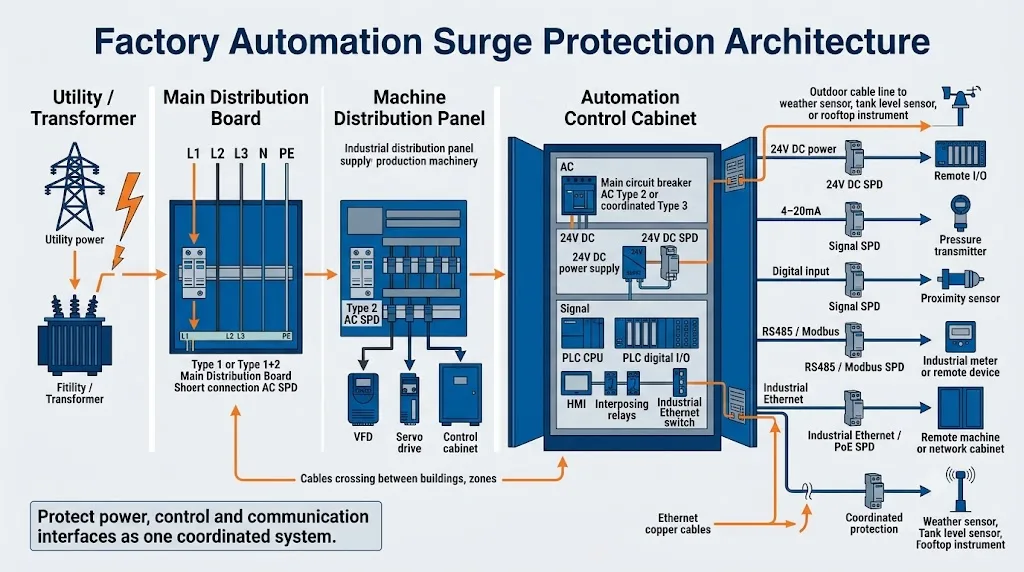
Conceptual architecture only. Final SPD type, rating and installation position must follow the site risk assessment, power system, cable routing, equipment immunity, local regulations and the selected manufacturer’s instructions.
Why this architecture matters: a surge can enter through the AC supply, but it can also arrive through a sensor cable, communication pair, shield, antenna line or copper link between buildings. Protecting one path does not automatically protect the others.
2. Where Surges Enter a Factory Automation System
Automation failures are often blamed on “bad power,” but the actual entry path may be outside the cabinet power circuit. The system review should trace every conductor connected to the PLC, HMI, controller, remote I/O or network switch.
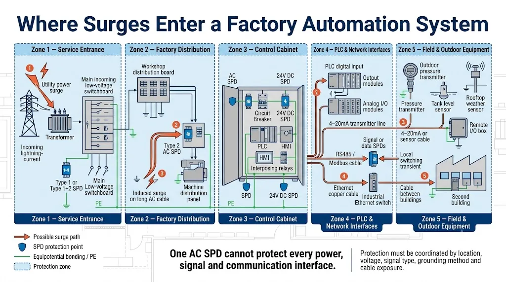
Utility and distribution transients
Lightning-induced surges, grid switching, fault clearing and upstream load changes can enter through the low-voltage supply.
Motors, contactors and inductive loads
Switching devices, coils, motors and other inductive loads can create transient overvoltages inside the facility.
24 V DC distribution
A shared DC bus can distribute a transient to several PLC modules, relays, sensors and remote I/O devices at once.
Outdoor sensor and actuator cables
Long copper runs can pick up induced energy and bring it directly to I/O terminals, bypassing the AC-side SPD.
RS485 and fieldbus lines
Differential communication ports remain vulnerable to common-mode and differential-mode transients.
Ethernet and inter-building copper
Copper Ethernet, including PoE, can conduct surge energy between cabinets, rooms or buildings with different local potentials.
Do not confuse surge protection with EMC filtering. An SPD limits short-duration transient overvoltage. Filters, shielding, segregation, ferrites and cable practices address continuous or repetitive high-frequency interference. Industrial systems may require both.
3. Protect the Power Path: Main Distribution, Control Cabinets and 24 V DC
3.1 Main low-voltage service entrance
The service entrance is the first power protection boundary. A Type 1 or Type 1+2 SPD may be required where lightning current can enter the installation—for example, because of an external lightning protection system, an exposed overhead supply or the result of a formal risk assessment. Do not specify Type 1 automatically for every factory; confirm the actual installation conditions and local rules.
3.2 Sub-distribution boards, MCCs and machine panels
Type 2 SPDs are commonly used downstream to limit residual incoming surges and switching transients. Selection must match the nominal voltage, earthing system, prospective short-circuit current, required backup protection, Uc, Up, discharge ratings and the coordination instructions of the selected SPD family.
3.3 Control-cabinet AC incoming feed
A local cabinet SPD can reduce the voltage reaching the control power supply, PLC and HMI, especially when the cabinet is remote from the upstream distribution SPD. The exact device may be Type 2, Type 2+3 or Type 3 depending on upstream protection, cable distance, equipment withstand and manufacturer coordination data.
3.4 24 V DC control power
Many automation systems convert AC to 24 V DC, but the DC side still needs its own review. The correct device depends on whether the circuit is a higher-current DC power feeder or a low-current signal loop.
24 V DC power bus
For a PLC or control-power distribution bus, confirm maximum continuous DC voltage, polarity, grounding arrangement, prospective fault current, operating temperature, Up, discharge capability and backup protection. General DC power SPDs are covered by IEC 61643-41:2025.[3]
24 V signal or sensor loop
A signal-line SPD is normally inserted in the signal path. It must also be checked for rated current, series resistance, voltage drop, leakage current, capacitance, line configuration and signal bandwidth under IEC 61643-21 and its application principles.[4][5]
Important VFD distinction: do not place a standard power SPD on a VFD motor output unless the drive and SPD manufacturers explicitly approve that application. PWM-related motor overvoltage is normally addressed with correct motor cable, grounding, output reactors, sine-wave filters or dV/dt filters. The cabinet supply side and control circuits remain separate surge-protection tasks.
For detailed upstream selection, see the SPD Selection Guide, SPD Uc Selection Guide and SPD Up Voltage Protection Level Guide.
4. PLC I/O, 4–20 mA and Sensor-Line Protection
PLC surge protection is not one product category with one universal voltage. The circuit function determines whether the protected path needs a power SPD, signal SPD or protocol-compatible data SPD.
| Interface | Typical use | Confirm before selecting | Common mistake |
|---|---|---|---|
| 24 V digital input | Limit switches, proximity sensors, dry-contact circuits | Line count, common reference, maximum normal voltage, input current, Up, grounding | Using a low-voltage data SPD that cannot carry the circuit current |
| 24 V digital output | Relays, solenoids, valve coils and indicator circuits | Load current, inductive load suppression, line configuration, voltage drop, follow current | Expecting the SPD to replace a flyback diode, RC snubber or coil suppression |
| 4–20 mA analog loop | Pressure, level, flow and temperature transmitters | Loop voltage, rated current, series resistance, leakage, HART compatibility where required | Selecting only by “24 V” and ignoring loop accuracy or communication overlay |
| RTD / thermocouple | Temperature measurement | Wire count, sensor type, measurement accuracy, low leakage and low thermal EMF requirements | Using a protector that adds unacceptable measurement error |
| Pulse / frequency input | Encoders, flow pulses and counters | Signal amplitude, pulse frequency, capacitance, insertion loss and shield connection | Choosing a device with insufficient bandwidth |
| Remote I/O trunk | Distributed I/O stations and field junction boxes | Power and data paths separately, cable route, outdoor exposure, local bonding and both endpoints | Protecting the control-room end but leaving the remote end exposed |
Where should signal SPDs be installed?
Install them where the field cable enters the cabinet or crosses a lightning protection zone boundary, with a short connection to the local bonding system. For exposed field devices or long external cables, protection may be required at both the control-system end and the field-device end. The two devices must be coordinated and compatible with the circuit.[5][8]
Practical panel-building rule: place the signal SPD near the cable-entry terminal section, not deep inside the cabinet beside the PLC after the unprotected cable has already crossed the cabinet.
5. RS485, Modbus, Fieldbus and Industrial Ethernet Protection
5.1 RS485 and Modbus RTU
RS485 and Modbus RTU use low-voltage differential signalling. The protector must be designed for the actual interface—not merely described as a “24 V SPD.” Confirm the working voltage, number of conductors, shield arrangement, data rate, capacitance, insertion loss and permissible residual voltage.
Install protection at exposed cable entry points and at endpoints that sit in different protection zones or local earth environments. Keep the RS485 termination and biasing design unchanged unless the network engineer approves a modification. An SPD does not replace correct termination, shielding or equipotential bonding.
5.2 CAN, PROFIBUS and other fieldbus systems
Protocol-compatible protection is essential. A device that works on a slow analog loop may distort a higher-frequency fieldbus. Check the manufacturer’s protocol approval or published transmission parameters rather than selecting only by connector shape.
5.3 Industrial Ethernet, PROFINET, EtherNet/IP and Modbus TCP
For copper Ethernet, confirm the supported category and data rate, shield continuity, connection method and PoE class. IEC 61643-21:2025 explicitly includes telecommunications and signalling networks that may carry power on the same line, such as PoE.[4]
When protection is especially important
Review copper links that leave a cabinet, run outdoors, cross buildings, approach roof-mounted equipment, connect remote cameras or pass between areas with different local bonding conditions.
Use fiber where practical
An optical-fiber link removes the conductive surge path between network nodes. Power supplies at each end still require local surge protection, but the data link itself no longer conducts lightning or ground-potential surge current.
For the RS485 subtopic, see the dedicated RS485 SPD Wiring and Selection Guide.
6. SPD Selection Matrix by Cabinet and Interface
This matrix is designed for project scoping and BOM preparation. It does not replace detailed product selection.
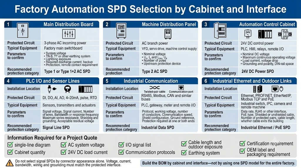
| Protection point | Typical equipment | Protection family | Key parameters to confirm | Applicable reference |
|---|---|---|---|---|
| Main LV switchboard | Factory service entrance | Type 1, Type 1+2 or Type 2 according to risk and installation | System voltage, TN/TT/IT arrangement, Iimp/In/Imax, Uc, Up, SCCR/backup protection | IEC 61643-11; IEC 60364 and local rules |
| Sub-distribution / MCC | Motor feeders, machine circuits, shop-floor boards | Coordinated Type 2 power SPD | Residual protection level, cable distance, earthing, backup fuse or MCB, remote contact | IEC 61643-11 |
| Control-cabinet AC input | PLC PSU, HMI, IPC, relays | Type 2, Type 2+3 or Type 3 as coordinated | Incoming voltage, upstream SPD, equipment withstand, installation lead length and available space | IEC 61643-11 |
| 24 V DC control bus | PLC, HMI, remote I/O and relay supply | DC power SPD | Maximum normal voltage, current, polarity, grounding, Up, fault current and backup protection | IEC 61643-41:2025 |
| 4–20 mA / analog loop | Transmitters and analog input cards | Signal-line SPD | Loop voltage/current, line count, series resistance, leakage, HART compatibility, field-end protection | IEC 61643-21 and IEC 61643-22 |
| Digital I/O | Sensors, switches, solenoids and relay interfaces | Signal or control-line SPD | Common/floating circuit, current, voltage drop, inductive suppression and wiring topology | IEC 61643-21 and IEC 61643-22 |
| RS485 / Modbus RTU | PLC, meter, gateway and remote I/O | Low-capacitance differential data SPD | Working voltage, data rate, A/B/COM/shield arrangement, grounding and endpoint placement | IEC 61643-21 and IEC 61643-22 |
| Industrial Ethernet / PoE | Switches, PLC ports, cameras, gateways and IPCs | RJ45 or DIN-rail network SPD | 10/100/1000 Mbps or higher, cable category, PoE type, shield, insertion loss and grounding | IEC 61643-21:2025 |
| Outdoor field device | Roof, tank farm, gate, water system or remote machine | Local power and signal protection | IP rating, temperature, cable exposure, enclosure, local bonding and coordinated protection at both ends | IEC 62305 LPZ concept; relevant SPD product standards |
Selection sequence: first identify the circuit; then identify the maximum normal operating conditions; then define the equipment withstand and required Up; only after that should you compare surge-current ratings, mounting format and optional features.
7. Example Protection Schedule for One PLC Control Cabinet
Engineering example — not a universal specificationThis example shows how a system integrator can convert a cabinet drawing into a preliminary protection schedule. It is intended to demonstrate the selection process, not to prescribe fixed SPD ratings for every factory.
| Circuit | Example interface | Example quantity | Protection requirement | Final data still required |
|---|---|---|---|---|
| Cabinet incoming power | 230 V AC, single phase | 1 circuit | Coordinated AC power SPD at the cabinet entry | Earthing system, upstream SPD, Uc, Up, short-circuit level and backup protection |
| PLC control-power bus | 24 V DC, 10 A | 1 bus | DC power SPD suitable for the maximum normal voltage and load arrangement | Maximum DC voltage, grounding, fault current, allowed voltage drop and installation temperature |
| Analog transmitters | 4–20 mA, two-wire | 8 loops | Low-resistance signal SPDs, with field-end protection reviewed for exposed cables | Loop voltage, HART requirement, shield connection, cable route and transmitter location |
| Digital field inputs | 24 V DC proximity sensors | 12 channels | Signal/control-line protection matched to the common and current arrangement | PNP/NPN topology, current, common reference, cable exposure and acceptable residual voltage |
| Remote meter network | RS485 / Modbus RTU | 1 bus | Low-capacitance differential data SPD at exposed endpoints | A/B/COM/shield arrangement, data rate, cable length, grounding and endpoint locations |
| Outdoor network link | 1 Gbps Ethernet with PoE | 1 link | Gigabit and PoE-compatible network SPD, or fiber conversion where practical | PoE class, cable category, shield, outdoor route, connector and local bonding |
Example only: the final SPD model and rating depend on the actual single-line diagram, normal operating conditions, equipment withstand, cable exposure, local standards and manufacturer coordination data.
8. What LEEYEE Can Support for Factory Automation Projects
LEEYEE is a specialized surge protection and low-voltage protection supplier. For factory automation projects, the practical starting point is to separate confirmed standard power-SPD requirements from interface-specific signal and network requirements that need technical review.
AC distribution and control-cabinet SPDs
Project matching can cover service entrance, sub-distribution, machine panels and cabinet incoming power according to the voltage, earthing system, installation category and required certification.
Project selection supportedLow-voltage DC power circuits
Selection requires the nominal and maximum DC voltage, load current, grounding arrangement, prospective fault current, required Up and mounting conditions.
Project selection supportedPLC I/O, 4–20 mA and sensor lines
Availability and matching must be confirmed from the exact interface data, including line count, current, series resistance, leakage, bandwidth, shielding and field exposure.
Technical confirmation requiredRS485, Modbus, Ethernet and PoE
Protocol, working voltage, data rate, conductor arrangement, PoE class, connector, cable category and grounding must be reviewed before a compatible device is proposed.
Technical confirmation requiredOEM and documentation support
For confirmed products and quantities, project discussions can include private labeling, packaging, datasheets, wiring information, sample approval and production scheduling. Availability depends on the selected product family and target-market certification requirements.
Best inquiry format: send the cabinet single-line diagram plus an interface list. LEEYEE can first organize the requirements by power, DC, signal and network circuit, then confirm which items are standard, which require a different product family and which need further engineering data.
9. Installation and Coordination Rules That Decide Real Protection
Do
- Keep SPD conductors short, direct and free of unnecessary loops.
- Bond to the local PE or equipotential bar with a suitable conductor.
- Separate protected wiring from unprotected incoming wiring.
- Place signal protection near the cable-entry terminal section.
- Use the manufacturer’s specified backup fuse or MCB arrangement.
- Confirm remote-status contact logic before wiring it to PLC monitoring.
Do Not
- Assume a main-board SPD protects PLC signal ports.
- Choose a signal SPD by nominal voltage alone.
- Mix a protected conductor back beside an unprotected cable.
- Use a standard AC/DC power SPD on a data interface.
- Use an SPD to solve normal VFD output PWM overvoltage or EMC noise.
- Daisy-chain a long earth path through unrelated cabinet devices.
Remote monitoring and maintenance
For unmanned or critical cabinets, specify visual status indication and a volt-free remote contact where available. Connect the contact to the PLC or monitoring system with clear alarm logic, and include inspection after major electrical events and during scheduled maintenance.
See How to Connect an SPD Remote Alarm Contact to a PLC and Common Causes of SPD Failure.
10. OEM and Project Ordering Checklist
A request such as “SPD for PLC cabinet” is not enough for reliable selection. Send the project information in groups so the supplier can build a cabinet-by-cabinet protection schedule.
Power system
- Nominal AC voltage and frequency
- Single-phase or three-phase
- TN-S, TN-C-S, TT or IT
- External LPS or overhead supply
- Prospective short-circuit current
- Upstream fuse or MCB details
DC control circuits
- Nominal and maximum DC voltage
- Maximum load current
- Positive, negative or floating grounding
- Power bus or signal loop
- Number of protected circuits
- Allowed voltage drop
Signal and network
- DI, DO, AI, AO, pulse or sensor type
- 4–20 mA, HART, RTD or thermocouple
- RS485, Modbus, CAN or PROFIBUS
- Ethernet speed and cable category
- PoE requirement
- Wire count, shield and connector
Installation environment
- Indoor or outdoor
- Cable length and route
- Inter-building or same-building link
- Temperature and humidity
- DIN-rail space
- Required enclosure or IP rating
Maintenance features
- Pluggable or fixed module
- Visual status indication
- Remote alarm contact
- Disconnect/test function
- Spare module quantity
- Replacement access requirements
Commercial requirements
- Cabinet quantity and annual forecast
- Required standards or certificates
- OEM label and packaging
- Datasheet and wiring diagram
- Sample approval process
- Target delivery schedule
Fastest way to request project matching
Send one cabinet drawing or a simple interface list. Mark each incoming and outgoing cable, then provide:
- AC system voltage
- 24 V DC load current
- PLC I/O types
- Communication protocols
- Outdoor cable lengths
- Cabinet quantities
- Required certificates
- OEM requirements
LEEYEE can review your power and signal interfaces and help organize a preliminary protection schedule for technical confirmation.
11. Frequently Asked Questions
Does a PLC control cabinet need surge protection?
It should be assessed whenever the cabinet is connected to an external power system, long field cables, remote sensors, motors, VFDs or copper communication networks. Protection normally covers the cabinet AC input, the DC control supply and exposed signal or data paths separately.
Is an SPD in the main distribution board enough to protect the PLC?
No. It can reduce surges entering through the power system, but it cannot stop a transient arriving through PLC I/O, RS485, Ethernet, sensor cables or another conductive path that bypasses the distribution board.
Where should a 24 V DC SPD be installed?
For a DC power bus, install the selected device close to the protected distribution point or equipment while following its wiring and backup-protection instructions. For a 24 V signal loop, use a signal SPD at the cable-entry or zone boundary and check current, resistance, leakage and bandwidth.
Should RS485 surge protection be installed at both ends?
Often yes for exposed, outdoor, inter-building or long links, because each endpoint may sit in a different electromagnetic or bonding environment. The final decision should follow the risk assessment, cable route and equipment arrangement. Both devices must be system-compatible and correctly bonded.
Can the same SPD protect 4–20 mA, digital I/O and RS485?
Not automatically. These circuits have different operating voltages, currents, bandwidths, line configurations and acceptable insertion characteristics. Use a device specifically selected for each interface.
Does an Ethernet surge protector reduce network speed?
A correctly selected network SPD should support the required Ethernet category and data rate with published insertion-loss and transmission performance. A mismatched or low-bandwidth device can reduce link quality, so confirm 100 Mbps, 1 Gbps, 10 Gbps and PoE compatibility as applicable.
Can an SPD solve VFD interference problems?
Not by itself. An SPD limits transient overvoltage. VFD-related EMC problems may require shielded motor cable, correct bonding, cable segregation, filters, reactors, ferrites or changes to the drive installation. Treat surge protection and EMC control as coordinated but separate tasks.
What information should a panel builder send for SPD selection?
Send the single-line diagram, AC voltage and earthing system, DC bus voltage and current, I/O list, communication protocols, cable lengths and routes, outdoor exposure, cabinet quantity, available DIN-rail space, required certifications and OEM requirements.
Related Engineering Guides
Technical References
- IEC 61643-01:2024 — Common requirements for low-voltage surge protective devices.
- IEC 61643-11:2025 — SPDs connected to AC low-voltage power systems.
- IEC 61643-41:2025 — SPDs connected to DC low-voltage power systems.
- IEC 61643-21:2025 — SPDs for telecommunications and signalling networks, including powered data lines such as PoE.
- IEC 61643-22:2015 — Selection and application principles for telecommunications and signalling network SPDs.
- Eaton / MTL: Protecting Against Electrical Surge in Industrial Applications — LPZ, equipotential bonding, power and signal protection principles.
- CITEL: Surge Protection for Programmable Logic Controllers — PLC power, I/O and network entry paths.
- Phoenix Contact: Surge Protection for MCR Technology and Signals — interface-specific protection for analog and digital field circuits.
- Phoenix Contact: Surge Protection for Information Technology — Ethernet, RS485 and high-speed network protection.
- Rockwell Automation Bulletin 4983 White Paper — surge and filter protection devices and industrial applications.
Engineering note: standards and local electrical rules can change. Confirm the current edition, national adoption and product certification requirements for the project market before final specification.
Send the Cabinet Drawing, Not Just a Voltage
A complete factory automation surge protection plan starts with the system architecture—not with a single SPD model. Send the incoming power, 24 V DC distribution, I/O list, communication interfaces and cable routes so LEEYEE can organize a preliminary cabinet-by-cabinet selection list for technical review and OEM ordering.
