
Ein Sicherungssymbol in einem Schaltplan kennzeichnet eine Sicherung im geschützten Strompfad. Die grafische Darstellung hilft Ihnen dabei, das Schutzorgan zu lokalisieren, doch das Symbol allein gibt keinen Aufschluss über Nennstrom, Nennspannung, Ausschaltvermögen, AC/DC-Eignung oder Sicherungskategorie. Dieser Leitfaden zeigt Ihnen, wie Sie das Symbol erkennen, gängige Kennzeichnungen wie F1lesen und eine Sicherung von anderen elektrischen Schutzsymbolen unterscheiden.
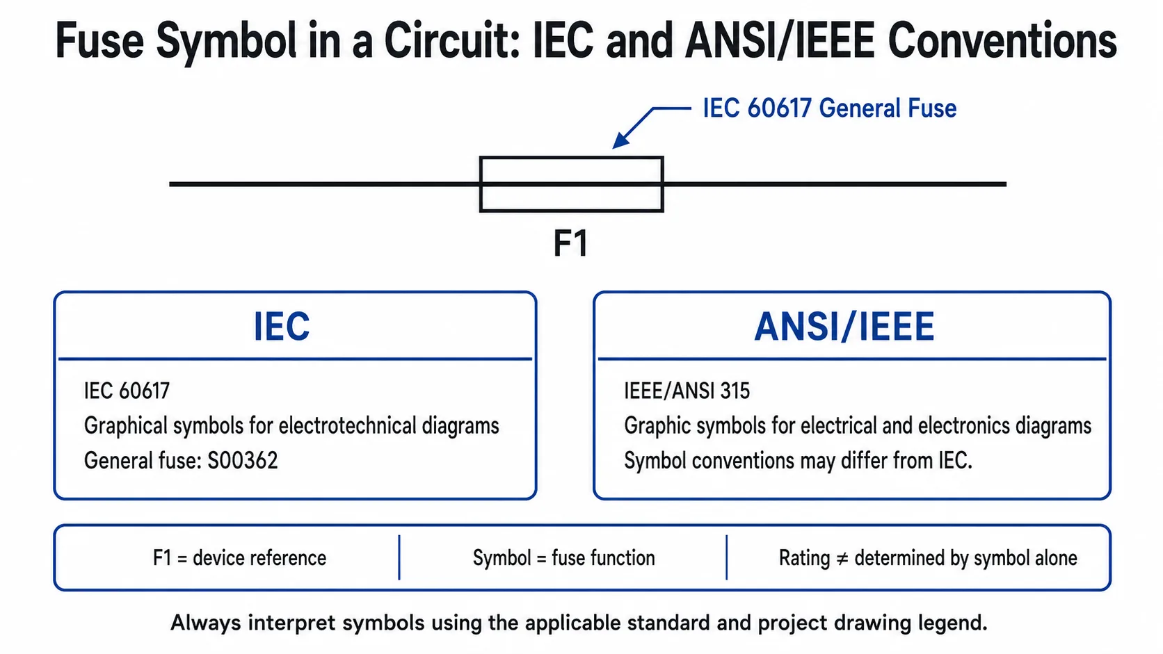
In Schaltplänen nach IEC-Norm wird die allgemeine Sicherungsfunktion durch das eingefügte Sicherungssymbol IEC 60617-S00362 dargestellt in Reihe mit dem Leiter, den sie schützt. Eine Referenz wie F1 identifiziert die jeweilige Sicherung in der Zeichnung. Das grafische Symbol zeigt an, dass eine Sicherungsfunktion vorhanden ist; Nennwerte und Anwendungsdetails müssen den beigefügten Anmerkungen, der Zeichnungslegende, dem Sicherungsplan, der Stückliste oder der Herstellerdokumentation entnommen werden.
Inhaltsübersicht
Wie sieht ein Sicherungssymbol in einem Schaltplan aus?
Der grundlegende Zweck des Symbols ist einfach: Es markiert den Punkt im Schaltplan, an dem eine Sicherung im Strompfad installiert ist. Gemäß IEC 60617 ist S00362 das allgemeine Sicherungssymbol. In einem horizontalen Schaltkreis wird das Symbol normalerweise in den Leiter gezeichnet; in einem vertikalen Schaltkreis kann dieselbe grafische Funktion in Richtung des Leiters ausgerichtet werden.
Dies unterscheidet sich von der Darstellung eines Fotos einer Glassicherung, NH-Sicherung, zylindrischen Sicherung, Flachsicherung oder PV-Sicherung. Ein Schaltplansymbol beschreibt den elektrische Funktion in der Zeichnung, nicht notwendigerweise die physische Konstruktion des installierten Produkts.
| Zeichnungselement | Was es üblicherweise vermittelt | Was es für sich genommen nicht beweist |
|---|---|---|
| Sicherungssymbol | In diesem Strompfad ist eine Sicherungsfunktion vorhanden. | Stromstärke, Spannung, Ausschaltvermögen, Sicherungsklasse, physikalische Abmessungen. |
| F1 | Referenzbezeichnung zur Identifizierung des Geräts in der Zeichnung. | Dass die Sicherung für 1 A ausgelegt ist oder einem bestimmten Sicherungstyp entspricht. |
| Bemessungsanmerkung | Zusätzliche ausgewählte Eigenschaften wie 32 A oder 500 V AC. | Alle Leistungsmerkmale, sofern sie nicht in der Zeichnung oder im Datenblatt anders angegeben sind. |
Sicherungssymbol in einem tatsächlichen Schaltplan
Der einfachste Weg, ein Sicherungssymbol zu verstehen, besteht darin, es nicht isoliert zu betrachten. In einem funktionsfähigen Schaltplan erscheint die Sicherung normalerweise in Reihe mit dem Leiter, der den geschützten Teil des Stromkreises speist.
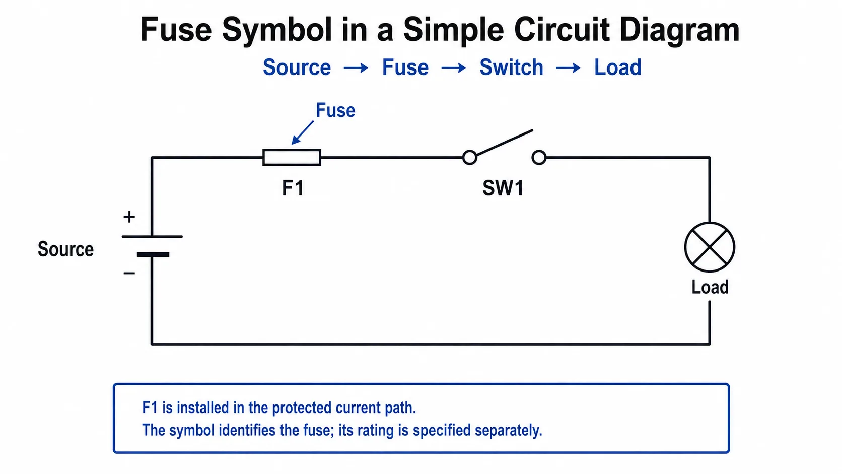
In diesem vereinfachten Beispiel lautet die Reihenfolge: Quelle → Sicherung F1 → Schalter SW1 → Last → Rückleitung. Der genaue physische Ort in einem realen System hängt vom Schaltungsdesign ab, die Zeichnung verdeutlicht jedoch die elektrische Beziehung der Sicherung zum geschützten Zweig.
Warum die Sicherung im Leiter erscheint
Der Strom des geschützten Stromkreises fließt durch den Sicherungseinsatz. Wenn Fehlerstrom- und Zeitbedingungen das Ansprechen des Sicherungselements bewirken, wird der Strompfad unterbrochen.
Warum die Position entscheidend ist
Ein Schaltplan ist mehr als nur eine Ansammlung von Symbolen. Die Konnektivität zeigt Ihnen, zu welchem Zweig die Sicherung gehört und welche nachgeschalteten Geräte diesem Schutzpfad zugeordnet sind.
Sicherungssymbol in einem industriellen Steuerstromkreis
In Schalttafeln kann eine Sicherung den Steuerspannungspfad schützen, der Schützspulen, Relais, Steuerungen, Transformatoren oder andere Steuergeräte versorgt. Das folgende Beispiel zeigt einen einfachen Reihenpfad von der Phase zum Neutralleiter.
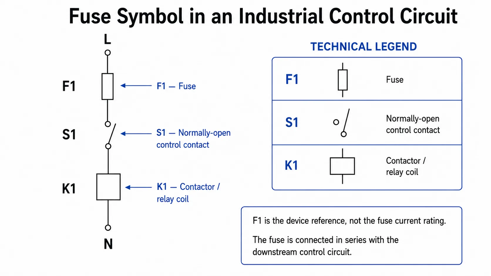
Hierbei F1 kennzeichnet die Sicherung, S1 identifiziert den Steuerkontakt und K1 identifiziert die Schütz- oder Relaisspule. Ihre Symbole haben unterschiedliche Funktionen, obwohl alle drei im selben Strompfad erscheinen.
IEC- im Vergleich zu ANSI/IEEE-Sicherungssymbolen
Elektroschaltpläne verwenden nicht immer dieselbe Symbolbibliothek. IEC 60617 ist die IEC-Datenbank für grafische Symbole, die in elektrotechnischen Schaltplänen verwendet werden. In nordamerikanischen und älteren technischen Dokumentationen können Sie auch auf Symbolkonventionen stoßen, die mit ANSI/IEEE 315 oder firmenspezifische CAD-Bibliotheken.
IEEE führt IEEE/ANSI 315-1975 als inaktiven, reservierten Standard. Bestehende Zeichnungen können dessen Konventionen noch verwenden; daher sollten Ingenieure, die ältere oder projektspezifische Dokumentationen lesen, nicht davon ausgehen, dass jeder Schaltplan dem aktuellen IEC-Symbolstandard entspricht.
| Frage | Zeichnung im IEC-Stil | ANSI/IEEE- oder Projektzeichnung |
|---|---|---|
| Symbolquelle | Datenbank für grafische Symbole nach IEC 60617. | Kann ANSI/IEEE-Referenzen, Altsystem-Konventionen oder Projektbibliotheken folgen. |
| Kann die Form variieren? | Verwenden Sie die zutreffende IEC-Symboldefinition. | Ja, die Konventionen können von der IEC abweichen. |
| Belegt das Symbol die Nennleistung? | Nein. | Nein. |
| Beste Interpretationsquelle | Anwendbare IEC-Norm sowie Projektlegende. | Zeichnungslegende, anwendbare Norm, Konstruktionsunterlagen. |
So lesen Sie F1, 32 A, gG und 500 V AC
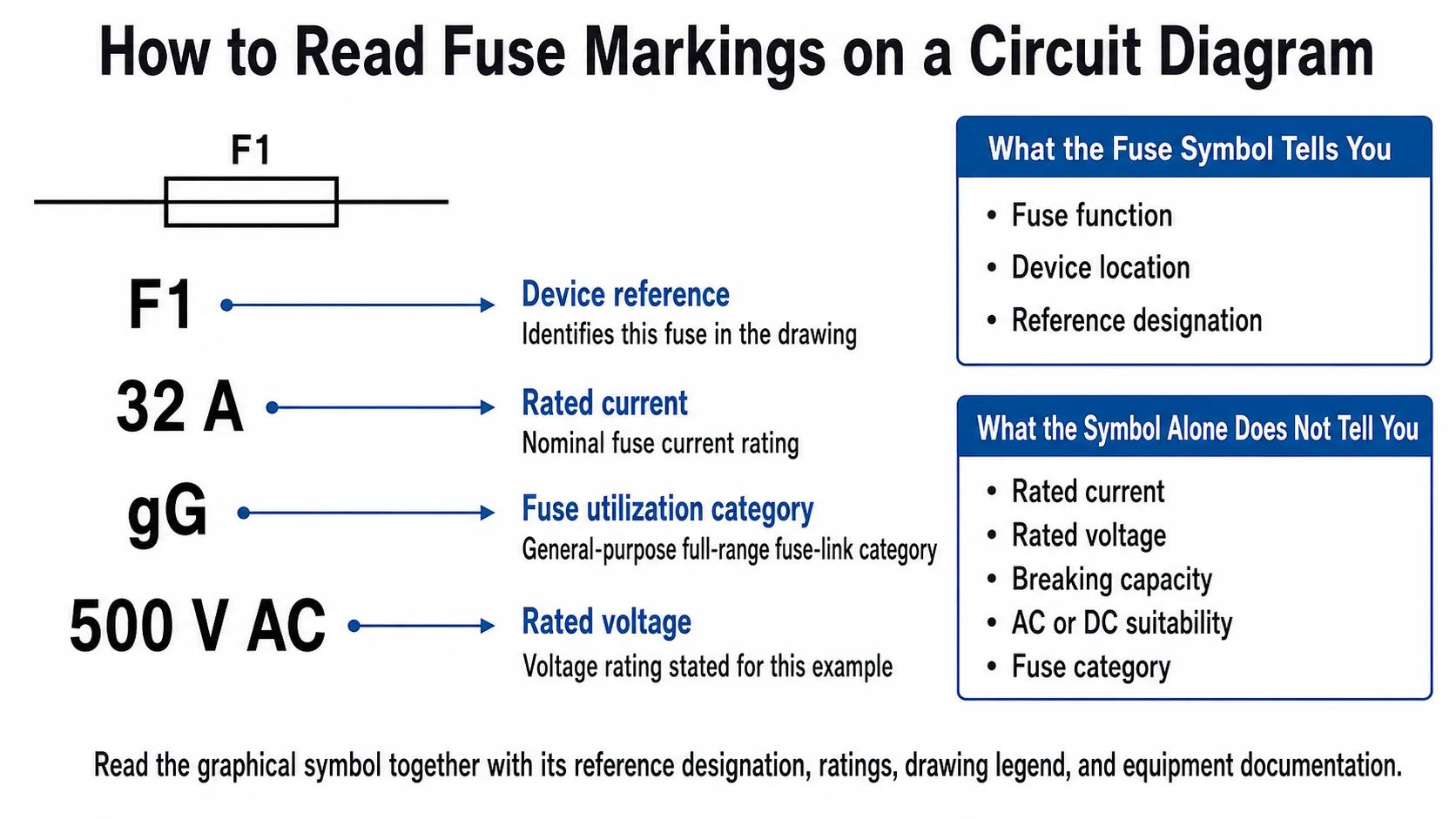
Ein Schaltplan wird oft wesentlich nützlicher, wenn das grafische Symbol mit einer Referenzkennzeichnung und Nennwerten kombiniert wird. Betrachten Sie das Beispiel:
F1 32 A gG 500 V AC
Was ein Sicherungssymbol aussagen kann – und was nicht
| Information | Kann das allgemeine Symbol Aufschluss darüber geben? | Wo dies zu bestätigen ist |
|---|---|---|
| Sicherungsfunktion ist vorhanden | Ja | Symbol- und Schaltkreisverbindung. |
| Geräteposition im Schaltplan | Ja | Schaltplanzeichnung. |
| Nennstrom | Nein | Anmerkung, Stückliste, Zeitplan, Datenblatt. |
| Nennspannung | Nein | Anmerkung oder Datenblatt. |
| Ausschaltvermögen | Nein | Sicherungsdatenblatt und geltende Norm. |
| Eignung für AC oder DC | Nein | Schaltungskontext, Spannungsbezeichnung, Produktdokumentation. |
| Sicherungskategorie | Nein | Kennzeichnung, Zeitplan, Datenblatt. |
| Physisches Format | Nein | Stückliste, Teilenummer oder Produktdokumentation. |
Aus diesem Grund reicht ein Schaltplan mit dem korrekten Symbol für die Beschaffung oder den Austausch nicht aus. Ein Techniker weiß zwar, wo die Sicherung hingehört, benötigt aber dennoch die genaue Teilenummer, die Abmessungen, die Nennspannung, den Nennstrom, die Nutzungskategorie, das Ausschaltvermögen und die Kompatibilität des Halters.
Sicherung vs. Sicherungshalter vs. Sicherungslasttrennschalter: Es sind nicht dieselben Komponenten
Ein weiterer häufiger Lesefehler besteht darin, jedes sicherungsbezogene Element als dieselbe Komponente zu betrachten. In der Praxis können Zeichnungen zwischen einem Sicherungseinsatz, dessen Halter und Sicherungskombinationsgeräten, die Schalt- oder Trennfunktionen hinzufügen, unterscheiden.
| Gerät | Hauptrolle | Wichtiger Interpretationspunkt |
|---|---|---|
| Sicherungseinsatz | Übernimmt die Funktion der Absicherung. | Wird üblicherweise nach dem Auslösen ersetzt. |
| Sicherungshalter | Hält und verbindet den kompatiblen Sicherungseinsatz elektrisch. | Der Halter selbst darf nicht mit dem austauschbaren Sicherungseinsatz verwechselt werden. |
| Sicherungslasttrennschalter | Kombiniert Sicherungsschutz mit Schaltfunktion. | Nicht als einfaches allgemeines Sicherungssymbol interpretieren. |
| Sicherungslasttrennschalter | Sicherungskombination mit Trennfunktion. | Die Trennfunktion ist bei der Interpretation der Gerätefunktion in einem Verteilerplan von Bedeutung. |
| Sicherungslasttrennschalter | Vereint Sicherungs-, Schalt- und Trennfunktionen. | Die genauen Geräteanforderungen sollten anhand der geltenden Norm und der Produktdokumentation überprüft werden. |
Die IEC 60947-3 deckt Lastschalter, Trennschalter, Lasttrennschalter und Sicherungslasttrennschalter ab, die in Niederspannungsverteilungen und Motorstromkreisen eingesetzt werden. Dies ist ein Grund, warum eine Zeichnung mehr als das einfache allgemeine Sicherungssymbol erfordern kann, wenn das Gerät zusätzliche Schalt- oder Trennfunktionen ausführt.
Suchen Sie nach dem physischen Gerät anstelle des Symbols?
Siehe das LEEYEE-Sortiment an Sicherungshalternoder informieren Sie sich im umfassenderen Bereich Was ist eine Sicherung? Leitfaden für Aufbau, Anwendung und Grundlagen der Auswahl von Sicherungen.
Verwenden AC- und DC-Sicherungen unterschiedliche Schaltzeichen?
Nicht unbedingt. Ein allgemeines Sicherungssymbol allein gibt keinen Aufschluss darüber, ob die installierte Sicherung für Wechsel- oder Gleichstrom zugelassen ist. Die gleiche allgemeine Sicherungsfunktion kann in Zeichnungen für verschiedene Systeme erscheinen, während die tatsächliche Konstruktion und die für diese Systeme erforderlichen Nennwerte der Sicherung sehr unterschiedlich sein können.
Systemkontext prüfen
Leitungs-/Neutralleiterbezeichnungen, Wechselspannungsbeschriftungen, Transformatorbeziehungen und der Geräteplan helfen dabei, das elektrische System zu bestimmen, in dem die Sicherung verwendet wird.
Auf Polarität und Gleichstromnennwerte achten
Positive/negative Leiter, DC-Bus-Beschriftungen, PV-String-Bezeichnungen, Batterieanschlüsse und explizite Gleichstromnennwerte sind aussagekräftiger als das allgemeine Sicherungssymbol allein.
Symbole für Sicherung, Leitungsschutzschalter und Widerstand im Vergleich
Diese drei Bauteile können alle in einem Leiterpfad vorkommen, ihre elektrischen Aufgaben unterscheiden sich jedoch grundlegend. Eine Verwechslung kann zu einer Fehlinterpretation der Schaltung führen.
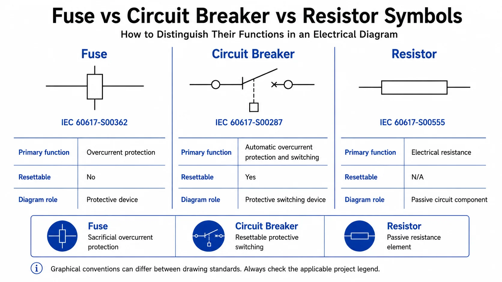
| Komponente | Hauptfunktion | Rücksetzbar? | IEC-Referenz dargestellt |
|---|---|---|---|
| Sicherung | Überstromschutz mittels austauschbarem Schmelzeinsatz. | Nein | IEC 60617-S00362 |
| Leitungsschutzschalter | Automatische Schutzschaltung, typischerweise für Überstromschutz gemäß Gerätetyp. | Ja | IEC 60617-S00287 |
| Widerstand | Dient als passives Schaltungselement zur Bereitstellung eines elektrischen Widerstands. | K.A. | IEC 60617-S00555 |
Ein Leitungsschutzschalter sollte zudem nicht mit einem Überspannungsschutzgerät (SPD) verwechselt werden. Eine herkömmliche Sicherung oder ein Leitungsschutzschalter ist primär eine Überstromschutzeinrichtung, während ein SPD dazu dient, transiente Überspannungen zu begrenzen und Stoßströme gemäß seiner Auslegung abzuleiten.
Informationen zur Schutzkoordination bei SPDs finden Sie unter Wie wählt man Sicherungen oder MCB für SPD.
Wie Sicherungssymbole in realen Schaltplänen dargestellt werden
1. Industrielle Schalttafeln
Steuerungsschaltpläne verwenden häufig Sicherungsbezeichnungen wie F1, F2 oder ähnliche Projektkennzeichnungen in Steuerstromkreisen. Die Zeichnung ist in Verbindung mit den Klemmennummern, Gerätebezeichnungen, Spulenreferenzen und der Stückliste zu lesen.
2. Verteilerschränke
In Verteilerplänen kann eine Sicherung vor einem Abzweig, einer Last, einem Transformator oder anderen Betriebsmitteln dargestellt sein. Wenn die Baugruppe zudem Schalt- oder Trennfunktionen übernimmt, kann in der Zeichnung anstelle eines einfachen Sicherungssymbols eine spezifischere Darstellung für Sicherungskombinationen verwendet werden.
3. Solar-PV- und Combiner-Box-Stromkreise
PV-Zeichnungen verdeutlichen den Unterschied zwischen Schutzfunktionen in Reihen- und Parallelschaltung. Eine PV-String-Sicherung wird im entsprechenden Strompfad installiert, während ein DC-Überspannungsschutzgerät üblicherweise als Schutzabzweig angeschlossen wird, anstatt wie eine Sicherung in Reihe geschaltet zu sein.
Für den PV-spezifischen Schutzkontext siehe den Leitfaden zum Überspannungsschutz für Photovoltaikanlagen sowie von LEEYEE Produkte für PV-Sicherungshalter.
Häufige Fehler bei der Interpretation von Sicherungssymbolen
Häufig gestellte Fragen
Welches Symbol wird für eine Sicherung in einem Schaltplan verwendet?
In Zeichnungen nach IEC-Norm ist IEC 60617-S00362 das allgemeine Symbol für eine Sicherung. Es wird in den Leiterpfad eingefügt, um die Sicherungsfunktion zu kennzeichnen. Andere Zeichensysteme können abweichende Konventionen verwenden, daher sollte auch die Projektlegende überprüft werden.
Was bedeutet F1 in einem Schaltplan?
F1 wird üblicherweise als Betriebsmittelkennzeichen verwendet, um eine bestimmte Sicherung in der Zeichnung zu identifizieren. Dies bedeutet nicht, dass die Sicherung für 1 A ausgelegt ist, und spezifiziert für sich genommen nicht den Sicherungstyp.
Unterscheidet sich das IEC-Sicherungssymbol von einem ANSI- oder IEEE-Sicherungssymbol?
Die grafischen Konventionen können variieren. IEC 60617 stellt elektrotechnische Symbole nach IEC bereit, während ältere oder projektspezifische nordamerikanische Zeichnungen ANSI/IEEE-Konventionen oder firmeneigene Symbolbibliotheken verwenden können. Verwenden Sie stets die Norm und die Legende, die für die jeweilige Zeichnung maßgeblich sind.
Hat eine Gleichstromsicherung ein anderes Schaltzeichen?
Nicht unbedingt. Das allgemeine Symbol allein lässt nicht zwangsläufig darauf schließen, ob die Sicherung für Wechsel- oder Gleichstrom vorgesehen ist. Überprüfen Sie Polarität, Systemspannung, Anmerkungen, Sicherungsliste und das Produktdatenblatt.
Gibt es ein separates Symbol für eine träge Sicherung?
Gehen Sie nicht davon aus, dass jede Auslösecharakteristik oder physische Sicherungsbauform ein eindeutiges, universelles Schaltzeichen besitzt. Die Betriebseigenschaften sollten anhand von Kennzeichnungen, Zeichnungsnotizen, der Stückliste oder der Herstellerdokumentation bestätigt werden.
Was ist der Unterschied zwischen einem Sicherungssymbol und einem Leitungsschutzschaltersymbol?
Sie repräsentieren unterschiedliche Schutzeinrichtungen. Eine Sicherung arbeitet mit einem Schmelzeinsatz, der nach dem Auslösen normalerweise ausgetauscht werden muss, während ein Leitungsschutzschalter ein rückstellbares Schutzschaltgerät ist. Die IEC 60617 weist ihnen daher unterschiedliche grafische Symbole zu.
Ist ein Sicherungshalter dasselbe wie eine Sicherung?
Nein. Ein Sicherungshalter stellt die mechanische und elektrische Verbindung für einen kompatiblen Sicherungseinsatz her. Der Sicherungseinsatz ist das Element, das die eigentliche Schutzfunktion übernimmt.
Kann ich die Nennstromstärke einer Sicherung an ihrem Symbol ablesen?
Nein. Nennstrom, Nennspannung, Ausschaltvermögen, Gebrauchskategorie und weitere Auswahlkriterien müssen den Anmerkungen, Stücklisten, dem BOM, Produktkennzeichnungen oder der technischen Dokumentation des Herstellers entnommen werden.
Technische Referenzen
Dieser Leitfaden unterscheidet zwischen standardisierten grafischen Symbolreferenzen und projektspezifischen Zeichnungskonventionen. Bestätigen Sie für technische Arbeiten stets die für die tatsächliche Installation geltende Ausgabe und die Anforderungen.
- IEC 60617-S00362 — Sicherung, allgemeines Symbol
- IEC 60617-S00287 — Leistungsschalter
- IEC 60617-S00555 — Widerstand, allgemeines Schaltzeichen
- IEC 60269-1 — Niederspannungssicherungen, allgemeine Anforderungen
- IEC 60947-3 — Niederspannungsschaltgeräte, Lastschalter, Trennschalter, Lasttrennschalter und Sicherungskombinationen
- IEEE/ANSI 315-1975 — Graphische Symbole für Schaltpläne der Elektrotechnik und Elektronik
Benötigen Sie eine Sicherung oder ein Überstromschutzprodukt für Ihre Anwendung?
Für OEM-, Vertriebs- oder Schaltschrankbauanforderungen senden Sie bitte Ihre Systemspannung, den Nennstrom, das Sicherungsformat, die Anwendung sowie den Zielmarkt an LEEYEE. Unser Team unterstützt Sie gerne bei der Auswahl der passenden Produktreihe und stellt die erforderlichen technischen Informationen bereit.
Technischer Hinweis: Die Interpretation von Schaltplänen ersetzt weder das Schaltungsdesign, die Sicherungskoordination, die Kurzschlussbewertung, die Herstelleranweisungen noch die für eine spezifische Installation geltenden Normen. Die elektrische Auslegung, Auswahl und Installation sollte durch qualifiziertes Fachpersonal erfolgen.
