
Eine Remote-I/O-Station, auch verteilte I/O-Station oder Feld-I/O-Knoten genannt, platziert Eingangs- und Ausgangsmodule in der Nähe von Sensoren und Aktoren. Anschließend verbindet sie die Station über ein Kommunikationsnetzwerk mit einer SPS, einem DCS oder einem Industriecontroller.
Diese Architektur reduziert die Feldverkabelung, setzt jedoch auch empfindliche Elektronik neben lokale 24V-Versorgung, lange Instrumentenkabel und freiliegende kupferbasierte Kommunikationsverbindungen. Die Frage des Schutzes lautet daher nicht einfach, ob die SPS über einen SPD verfügt. Entscheidend ist, ob jeder leitfähige Pfad, der in die Remote-I/O-Station hineinführt, geprüft wurde.
Inhaltsübersicht
Schnelle Antwort
Eine Remote-I/O-Station benötigt nicht automatisch an jedem Kanal einen SPD.
Überspannungsschutz sollte geprüft werden, wenn die Station mit Außenanlagen, langen Feldkabeln, Leitern zwischen Gebäuden, getrennten Erdungszonen oder freiliegenden RS485- und Ethernet-Verbindungen verbunden ist.
Prüfen Sie die Station als drei getrennte Pfade: 24V DC-Versorgung, Feld-I/O und Kommunikations-Backhaul. Wählen und positionieren Sie den Schutz für jeden Pfad entsprechend seiner tatsächlichen Spannung, seinem Strom, seinen Signalmerkmalen, seiner Isolationsanordnung, der Kabelexposition und dem Erdungskonzept.[1][2][3]
Prüfungen der Störfestigkeit von Anlagen gegen Überspannungen und die Auslegung von Feld-SPDs stehen in Zusammenhang, sind aber nicht identisch. IEC 61000-4-5 definiert eine wiederholbare Störfestigkeitsprüfung für Geräte. Sie genehmigt für sich genommen nicht jede fertiggestellte Installation, jeden Kabelweg oder jede Erdungsanordnung.[4]
Wesentliche behandelte Entscheidungen
- Wann eine Remote-I/O-Station Schutz benötigt
- Wie die Station in drei Überspannungspfade zu unterteilen ist
- Wie sich lokale und zentrale 24V-Versorgungen unterscheiden
- Wie DI, DO, AI und AO die Auswahl beeinflussen
- Wie RS485, Ethernet und Glasfaser das Design verändern
- Wo SPDs an jeder Stationsgrenze zu installieren sind
- Wie ein Schutzplan auf Stationsniveau vorzubereiten ist
- Welche Nachweise ein OEM-Käufer freigeben sollte
Wann benötigt eine Remote-I/O-Station Überspannungsschutz?
Die Entscheidung sollte mit der Kabelexposition beginnen, nicht nur mit der Remote-I/O-Marke, dem Modultyp oder der gesamten Kanalzahl.
Verteilte I/O-Systeme erfassen Signale in der Nähe des Prozesses und übertragen sie an eine zentrale Steuerung. Die Remote-Station kann daher in einem Maschinengehäuse, einem Außenschaltschrank, einer Pumpstation, einem Förderanlagenabschnitt, einer vorgefertigten Skid-Einheit oder einem separaten Gebäude installiert sein.[5]
Nutzen Sie den Kabelweg und die elektrische Grenze, um zu entscheiden, welche Pfade eine detaillierte Prüfung benötigen.
| Installationsbedingung | Wahrscheinliche Exposition | Technische Reaktion |
|---|---|---|
| Alle Verdrahtung bleibt innerhalb eines einzigen gebondeten Gehäuses | Geringere externe Blitzexposition, obwohl Lastschaltungen und interne Störungen dennoch auftreten können. | Prüfen Sie die Störfestigkeit der Ausrüstung, den Schaltschrank-Überspannungsschutz und die Lastunterdrückung, bevor Sie Kanal-SPDs hinzufügen. |
| Lange Feldkabel verlassen die Station | Überspannungstransienten können auf Instrumenten- oder Steuerleiter eingekoppelt werden. | Bewerten Sie den Signal-Schutz an der Kabeleintrittsgrenze der Station. |
| Außensensoren oder -aktoren | Die Feldverdrahtung kann durch induzierte Überspannung und lokale Erdpotenzialunterschiede beeinträchtigt werden. | Bewerten Sie den koordinierten Schutz auf Stations- und Feldebene. |
| Kupferkabel überbrückt Gebäude | Die beiden Kabelenden können mit getrennten Äquipotentialzonen verbunden sein. | Prüfen Sie beide Enden, die Potentialausgleichsverbindung, die Schirmung und die Option der Glasfaserkommunikation. |
| Außen- oder unbemannter Fernschrank | Strom-, E/A- und Kommunikationskabel können über ungeschützte Leitungswege eingeführt werden. | Bewerten Sie jeden eingehenden Kupferpfad und legen Sie Inspektions- sowie Austauschverfahren fest. |
Hinweis für den Käufer: Fragen Sie nicht zuerst, wie viele SPDs benötigt werden. Ermitteln Sie stattdessen, welche Leiter eine Grenze zwischen Anlagen, Gebäuden, Erdungssystemen oder Blitzschutzbereichen überschreiten.
Behandeln Sie die Remote-I/O-Station als drei Schutzpfade
Eine Remote-I/O-Station ist zwar eine physische Baugruppe, stellt jedoch keinen einzelnen elektrischen Stromkreis dar. Sie kombiniert in der Regel ein Gleichstromversorgungssystem, mehrere Feldschnittstellengruppen sowie mindestens eine Kommunikationsschnittstelle.
Die Norm IEC 61643-21 befasst sich mit SPDs, die an Telekommunikations- und Signalisierungsnetzwerke angeschlossen sind. Die IEC 61643-22 regelt deren Auswahl, Betrieb, Standort und Koordination. Die IEC 61643-21:2025 umfasst zudem Netzwerke, die Strom über dieselbe Leitung übertragen, einschließlich Power over Ethernet.[1][2]
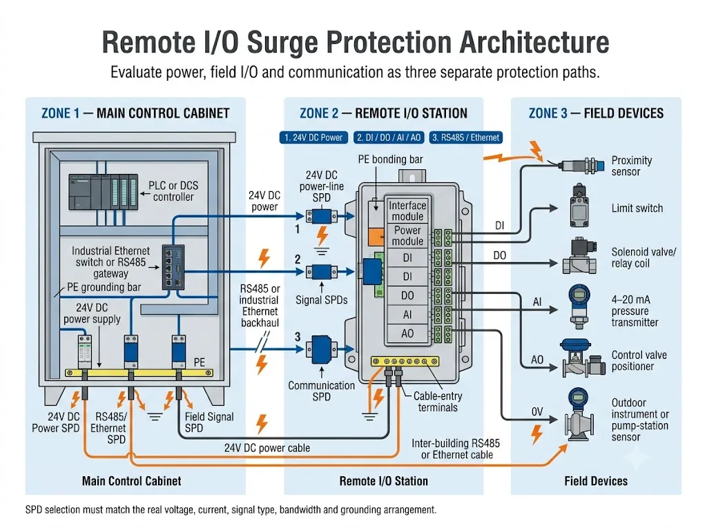
| Schutzweg | Typische Leiter | Auswahlfaktoren | Hauptfehler |
|---|---|---|---|
| 24V DC Stromversorgung | L+, M oder 0V, lokale Stromversorgung und zusätzliche DC-Einspeisung. | Maximale Betriebsspannung, Stromstärke, Polarität, Erdungskonzept und Schutzart. | Die Auswahl eines Geräts allein aufgrund der Systembeschreibung „24V“. |
| Feld-E/A | DI-, DO-, AI-, AO-, Sensor-, Messumformer-, Relais-, Ventil- und Stellantriebsschaltkreise. | Signaltyp, Stromstärke, Leckstrom, Widerstand, Kapazität, Bandbreite und gängige Anordnung. | Verwendung einer einzigen SPD-Signalspezifikation für jeden Kanaltyp. |
| Kommunikations-Backhaul | RS485, Modbus RTU, PROFIBUS, CAN, Industrial Ethernet, PROFINET oder PoE. | Protokoll, Leiteranordnung, Impedanz, Datenrate, Schirmung, Steckverbinder und PoE-Anforderung. | Verwendung eines Überspannungsschutzgeräts für Strom- oder langsame Signalübertragungen in einem Hochgeschwindigkeitsnetzwerk. |
Der Schutz des AC-Eingangs des Hauptschaltschranks schützt nicht automatisch die dezentrale I/O-Station. Überspannungsenergie kann die Station weiterhin über die lokale DC-Versorgung, Feldkabel oder Kupfer-Backhaul-Verbindungen erreichen.
Verwenden Sie eine Prüfung auf Stationsebene statt einer rein kanalbezogenen Prüfung
Eine kanalbezogene Überprüfung klärt, ob ein DI-, AO- oder RS485-Port einen SPD benötigt. Eine stationsbezogene Überprüfung analysiert, wo Überspannungen eintreten können, welche Module eine Potenzialgruppe teilen und welche Geräte am anderen Kabelende ungeschützt bleiben.
-
Erfassen Sie jeden ein- und ausgehenden Leiter.
Berücksichtigen Sie Stromversorgungs-, I/O-, Kommunikations-, Schirm-, Beilauf- und Hilfsleiter. -
Bestimmen Sie die Stromversorgungsarchitektur der Station.
Überprüfen Sie, ob die Station eine lokale Gleichstromversorgung nutzt oder 24V vom Zentralschrank bezieht. -
Gruppieren Sie Kanäle nach ihrem elektrischen Verhalten.
Gruppieren Sie Stromkreise nicht ausschließlich aufgrund ihrer Installation im selben E/A-Modul. -
Markieren Sie die Trennung von Potenzialgruppen und deren Grenzen.
Stellen Sie fest, welche Kanäle sich 0V teilen und welche Schnittstellen galvanisch getrennt sind. -
Definieren Sie die Schutzgrenze.
Legen Sie fest, wo die ungeschützte Feldverdrahtung endet und die geschützte Stationsverdrahtung beginnt. -
Erstellen Sie einen Schutzplan.
Erfassen Sie den SPD-Typ, den Stromkreis, die Menge, den Installationsort sowie die für die Genehmigung erforderlichen Nachweise.
Die detaillierte Auswahl der Signalstromkreise bleibt wichtig, doch der Zweck dieser Seite ist die vollständige Remote-I/O-Station. Für tiefergehende Anleitungen zu DI-, DO-, AI- und AO-Stromkreisen siehe die Leitfaden zum Überspannungsschutz für SPS-I/O-Signale.
Wie sollte die 24V DC-Versorgung geprüft werden?
Die erste Frage ist, ob die Remote-I/O-Station 24 V vom Hauptschaltschrank erhält oder diese lokal erzeugt.
Zentrale 24-V-DC-Einspeisung
Eine zentrale Einspeisung kann über eine beträchtliche Strecke parallel zu Feld- oder Stromkabeln verlaufen. Der Stromeingang der dezentralen E/A-Einheit kann daher selbst dann gefährdet sein, wenn die vorgeschaltete Wechselstromversorgung bereits abgesichert ist.
Überprüfen Sie die Kabelführung, die Leiterlänge, den Laststrom, den Spannungsabfall sowie den erforderlichen Schutz am Eingang der dezentralen Station.
Lokale 24V DC-Stromversorgung
Ein lokal installiertes AC/DC-Netzteil verändert den Pfad. Das Projekt muss den lokalen AC-Eingang, den DC-Ausgang zur Versorgung der dezentralen E/A-Module sowie alle langen 24V-Stromkreise, die aus dem Gehäuse herausführen, bewerten.
Ein AC-Überspannungsschutz am Eingang des lokalen Schaltschranks schützt nicht automatisch alle nachgeschalteten Signal- und Kommunikationswege.
Bevor Sie ein DC-Überspannungsschutzmodell festlegen, bestätigen Sie:
- Die Nenn- und maximale Betriebsspannung, einschließlich Toleranz und Restwelligkeit.
- Ob der Stromkreis geerdet, erdfrei, SELV, PELV oder Teil einer anderen definierten Anordnung ist.
- Der Stationsstrom sowie jeglicher Strom, der für Feldlasten bereitgestellt wird.
- Die erforderlichen Schutzmodi zwischen Leitern und gegenüber PE.
- Die vom Hersteller der Remote-I/O zugelassene Versorgungs- und Isolationsanordnung.
- Die zulässige Restspannung für die angeschlossenen Leistungs- und Schnittstellenmodule.
Eine Gleichstrom-Einspeisung kann den kombinierten Strom der Stations- und Feldlasten führen. Ein 24-V-Signalkanal führt hingegen nur einen geringen Mess- oder Steuerstrom. Ihre Strombelastbarkeit in Reihe, ihr Widerstand, ihre Anschlüsse und ihr Schutzverhalten können sich unterscheiden.
Wie wirken sich DI, DO, AI und AO auf den Stationsentwurf aus?
Der Stationsplan sollte Kanäle nach ihrem elektrischen Verhalten gruppieren. Es sollte nicht davon ausgegangen werden, dass jedes Modul mit der Kennzeichnung DI, DO, AI oder AO dieselbe Schaltungsanordnung verwendet.
Texas Instruments unterscheidet zwischen den Schutzanforderungen für hochohmige Eingänge und niederohmige Ausgänge. Die Richtlinien zum E/A-Schutz weisen zudem darauf hin, dass Leckströme von Schutzgeräten analoge Messkreise beeinflussen können.[6]
Verwenden Sie diese Tabelle, um zu entscheiden, welche Kanalgruppen gemeinsam überprüft werden können.
| Kanalgruppe | Für den Sendeplan bestätigen | Hauptkompatibilitätsrisiko |
|---|---|---|
| DI | Potenzialfreier oder gespeister Sensor, PNP/NPN-Logik, Spannung, gemeinsamer Anschluss und Aderanzahl. | Leckströme oder ein fehlerhafter Referenzanschluss können zu einem falschen Eingangszustand führen. |
| DO | Transistor- oder Relaisausgang, Dauerstrom, Einschaltstrom, induktive Last und lokale Entstörung. | Ein zu hoher Widerstand oder eine unzureichende Strombelastbarkeit können die Last beeinträchtigen. |
| AI | 4–20 mA, 0–10 V, RTD oder Thermoelement, Schleifentopologie, Leckstromgrenzwert und zulässiger Widerstand. | Leckströme oder zusätzlicher Widerstand können zu Messfehlern führen. |
| AO | Aktiver oder passiver Ausgang, Ausgangsbereich, Lastwiderstand, gemeinsames Bezugspotenzial und zulässiger Spannungsabfall. | Eine fehlerhafte Klemmung oder Reihencharakteristik kann den Steuerausgang einschränken. |
| Impuls- oder Hochgeschwindigkeitseingang | Signalamplitude, maximale Frequenz, Flankensteilheit, Kapazität und Einfügungsdämpfung. | Ein ungeeigneter Überspannungsschutz kann das Signal verzerren oder zu fehlenden Impulsen führen. |
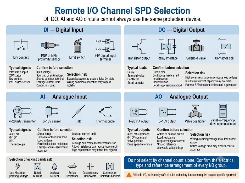
Ausfallsichere E/A, eigensichere Schleifen, explosionsgeschützte Stromkreise und sicherheitstechnische Funktionen erfordern eine modellspezifische Zulassung. Fügen Sie keinen Überspannungsschutz hinzu und ersetzen Sie keinen, ohne das Handbuch für das Remote-I/O-System, die Dokumentation zur funktionalen Sicherheit und die geltenden Anforderungen für explosionsgefährdete Bereiche zu prüfen.
Wie sollte die Kommunikations-Backhaul-Verbindung geschützt werden?
Das Backhaul verbindet die Außenstation mit einem Controller, Gateway oder Industrial Switch. Es kann zudem eine leitende Verbindung zwischen getrennten Anlagenbereichen herstellen.
RS485, Modbus RTU und ähnliche serielle Netzwerke
Überprüfen Sie die A/B-Leiteranordnung, die Signalreferenz, die Betriebsspannung, die Datenrate, die Kabelimpedanz, den Schirmanschluss und die Netzwerktopologie.
Ein allgemeiner 24V-Überspannungsschutz sollte nicht automatisch als für RS485 geeignet angesehen werden. Spezielle Signalgeräte sind auf die Schnittstellenschaltung, Stromstärke, Kapazität, Einfügungsdämpfung und Übertragungsanforderungen ausgelegt.[7][8]
Industrie-Ethernet und PoE
Überprüfen Sie die Ethernet-Kategorie, Übertragungsrate, den Steckverbinder, die Kabelabschirmung sowie die PoE-Anforderungen. Der Überspannungsschutz (SPD) muss die normale Netzwerkleistung und die Leiteranordnung gewährleisten.
Die Norm IEC 61643-21:2025 umfasst Telekommunikations- und Signalisierungsnetzwerke, die über dieselbe Leitung auch Strom übertragen können, einschließlich PoE.[1]
Glasfaser-Backhaul
Glasfaser eliminiert den leitfähigen Überspannungspfad von der Datenverbindung selbst. Dies entbindet jedoch nicht von der Notwendigkeit, die Gleichstromversorgung der Gegenstelle, die Stromversorgung der Medienkonverter sowie die kupferbasierten Feldstromkreise zu überprüfen.
Bei der Kommunikation zwischen Gebäuden oder weit voneinander entfernten Erdungszonen kann Glasfaser den Schutz des Backhauls vereinfachen. Die endgültige Entscheidung muss dennoch Verfügbarkeit, Redundanz, Konverterleistung und die Kommunikationsanforderungen des Projekts berücksichtigen.
Wie wirken sich 0V, Schirm, Funktionserde und PE auf den Entwurf aus?
Der Begriff „Erde“ wird in Automatisierungszeichnungen häufig zu allgemein verwendet. Ein dezentrales E/A-System kann einen DC-Rückleiter, eine Signalreferenz, einen Schutzleiter, eine Funktionserde und eine Kabelschirmung enthalten. Diese Leiter erfüllen nicht automatisch dieselbe Funktion.
Die Dokumentation des Herstellers der Remote-I/O-Module sollte geerdete oder ungeerdete Bezugspotenziale, galvanische Trennung sowie Potenzialgruppen ausweisen. Die gewählte SPD-Schaltung muss mit dieser Anordnung kompatibel sein.[5]
- L+: positiver DC-Versorgungsleiter.
- M or 0V: Leitungsrückführung oder Signalbezugspunkt gemäß Geräteauslegung.
- Sportunterricht: Schutzerde und ein potenzieller Bezugspunkt für Überspannungsableitungen.
- Funktionserde: ein EMV-Bezugspunkt mit einer spezifischen Gerätefunktion.
- Kabelschirm: Ein gemäß dem EMV- und Erdungskonzept des Projekts verbundener Schirm.
Verbinden Sie 0V, Schirm und PE nicht allein deshalb miteinander, weil sie sich innerhalb des Gehäuses in unmittelbarer Nähe befinden. Eine fehlerhafte Verbindung kann die beabsichtigte Isolierung umgehen, Ausgleichsströme erzeugen oder transiente Energie direkt über eine Kommunikationsschnittstelle leiten.
Fordern Sie einen Schaltplan an, der die Potenzialgruppen, Isolationsgrenzen, Schirmanschlüsse und die PE-Anordnung aufzeigt. Ein Gerät mag zwar die korrekte Spannungsfestigkeit aufweisen, jedoch für die Netzwerktopologie über die falsche Schutzschaltung verfügen.
Wo sollten Remote-I/O-SPDs installiert werden?
IEC 61643-22 befasst sich mit der Auswahl, Anordnung und Koordination von Überspannungsschutzgeräten (SPDs), die an Signalnetzwerke angeschlossen sind. IEC 62305-4 behandelt Blitzschutzmaßnahmen für elektrische und elektronische Systeme innerhalb von Gebäuden.[2][3]
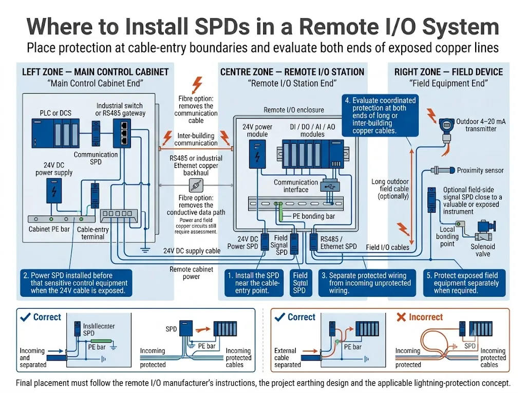
In der praktischen Umsetzung wird der Schutz dort bewertet, wo ein ungeschütztes Kabel in den geschützten Gerätebereich eintritt. Ziel ist es, transiente Ströme von empfindlichen Modulen fernzuhalten und einen kurzen, direkten Pfad zum vorgesehenen Potenzialausgleichspunkt bereitzustellen.
-
Identifizieren Sie jedes Kabel, das in die Station eintritt.
Trennen Sie Gleichstromversorgungs-, Feld-E/A-, serielle Bus-, Ethernet-, Schirm- und Hilfsleiter voneinander. -
Definieren Sie die geschützte und die ungeschützte Seite.
Führen Sie einen ungeschützten eingehenden Leiter nicht tief in das Gehäuse ein, bevor er den SPD erreicht. -
Platzieren Sie den Schutz nahe an der Kabeleinführungsgrenze.
Halten Sie die Verbindung zum spezifizierten PE- oder Potenzialausgleichspunkt kurz und direkt. -
Trennen Sie eingehende und geschützte Leitungen.
Vermeiden Sie die Bündelung von ungeschützten, vorgelagerten Leitungen mit geschützten, nachgelagerten Leitern. -
Überprüfen Sie das gegenüberliegende Ende der freiliegenden Kupferkabel.
Bei Außenverlegung, zwischen Gebäuden oder zwischen getrennten Potenzialausgleichszonen kann an beiden Enden ein koordinierter Schutz erforderlich sein. -
Überprüfen Sie die Installation anhand des Gerätehandbuchs.
Die Erdungskonzeption des Projekts sowie die Herstelleranweisungen für die Remote-I/O haben Vorrang vor einem allgemeinen Schaltplan.
An der Remote-I/O-Station
- Installieren Sie den DC-Schutz, bevor die freiliegende Versorgungsleitung das Stationsstrommodul oder die Potenzialgruppe erreicht.
- Installieren Sie den Signalschutz, bevor freiliegende Feldleiter empfindliche I/O-Anschlüsse erreichen.
- Platzieren Sie den Kommunikationsschutz, bevor die Kupferleitung das Schnittstellenmodul, Gateway oder den Switch erreicht.
- Schließen Sie den Überspannungsschutz (SPD) ohne unnötige Schleifen oder Umwege an den vorgesehenen Erdungspunkt an.
Am Hauptsteuerschrank
- Überprüfen Sie das Controller-Ende eines freiliegenden seriellen, Feldbus- oder Ethernet-Kabels.
- Platzieren Sie den Schutz, bevor die Leitung die SPS, das Gateway oder den Industrial-Switch erreicht.
- Achten Sie auf eine physische Trennung zwischen der eingehenden Feldzone und der geschützten Steuerungsverkabelung.
Am Feldgerät
Ein stationärer Überspannungsschutz dient primär dem Schutz des Remote-I/O-Terminals. Er bietet möglicherweise keinen ausreichenden Schutz für exponierte Messumformer, Sensoren oder Aktoren am Ende einer langen Leitung.
Bewerten Sie für freiliegende oder hochwertige Feldgeräte einen koordinierten feldseitigen Überspannungsschutz (SPD). Stellen Sie sicher, dass zusätzlicher Widerstand, Leckstrom und Kapazität für den normalen Schaltkreis akzeptabel bleiben.
Erstellen Sie einen Schutzplan für die Remote-I/O-Station
Ein Stationsschutzplan wandelt den Entwurf in ein Dokument um, das von Schaltschrankbauern, Einkäufern und Projektprüfern genehmigt werden kann.
Eine Zeile sollte einen elektrischen Pfad oder eine Kanalgruppe darstellen. Fassen Sie nicht alle Stationsstromkreise in einer allgemeinen Zeile mit der Bezeichnung „Signal-SPD“ zusammen.
| Position im Plan | Aufzuzeichnende Informationen | Warum es wichtig ist |
|---|---|---|
| Geschützter Pfad | 24V-Stromversorgung, DI-Gruppe, AI-Schleife, RS485-Backhaul oder Ethernet-Verbindung. | Verhindert, dass verschiedene elektrische Funktionen als ein einziger Stromkreis behandelt werden. |
| Quelle und Ziel | Hauptschaltschrank, abgesetzte Station, Feldgerät, Aktor oder angrenzendes Gebäude. | Zeigt an, welche Geräte durch den jeweiligen SPD geschützt werden sollen. |
| Elektrische Daten | Spannung, Strom, Signalbereich, Protokoll, Frequenz oder Datenrate. | Bestätigt die Kompatibilität für den Normalbetrieb. |
| Referenzanordnung | Gemeinsame 0V, erdfreies Paar, isolierter Kanal, Schirm- und PE-Anschluss. | Bestimmt die erforderlichen Schutzmodi und die Anschlussbelegung. |
| Installationsposition | Hauptschaltschrank, Stationszugang oder feldseitiger Anschluss. | Verhindert die Installation des falschen Überspannungsschutzes an der unzutreffenden Schnittstelle. |
| Mengen- und Ersatzteilstrategie | Installierte Menge, Ersatzteilmenge und Austauschmethode. | Unterstützt die Stücklistenverwaltung für Schalttafeln sowie die zukünftige Wartung. |
Der Schutzplan kann in die Stückliste der Schalttafel, den Schaltplan und das Paket zur Musterfreigabe aufgenommen werden. Dies verhindert zudem, dass das Einkaufsteam mehrere anwendungsspezifische Geräte durch ein oberflächlich ähnliches Modell ersetzt.
Genehmigungsmatrix für ein Remote-I/O-SPD-Projekt
Ein Datenblatt ist erforderlich, stellt jedoch nicht das vollständige Genehmigungspaket dar. Jede Entscheidung sollte durch entsprechende Nachweise belegt werden.
| Genehmigungspunkt | Anforderungsnachweis | Genehmigungsentscheidung |
|---|---|---|
| Schaltungskompatibilität | Schaltplan für Remote-I/O, SPD-Schaltplan und Klemmenbelegung. | Schutzmodi und allgemeine Anordnung bestätigen. |
| Normalbetrieb | Daten zu Uc, Nennstrom, Widerstand, Ableitstrom und Spannungsabfall. | Sicherstellen, dass der normale Strom- oder Signalbetrieb nicht beeinträchtigt wird. |
| Signalintegrität | Daten zu Kapazität, Einfügungsdämpfung, Frequenzbereich oder Übertragungsrate. | Direkte Genehmigung erteilen oder eine Kommunikation- bzw. Schleifenprüfung anfordern. |
| Überspannungsschutzleistung | Modellspezifische Konformitätserklärung, Prüfbericht oder technische Unterlagen des Herstellers. | Das genaue Modell und den Prüfumfang verifizieren. |
| Einbaupassung | Abmessungen, Klemmenbelegung, PE-Anordnung und Zeichnung der DIN-Schiene. | Platzbedarf im Schaltschrank, Verdrahtungszugang und Erdungspfad prüfen. |
| OEM-Lieferung | Etikettenentwurf, Datenblatt, Verdrahtungsunterlagen und Verpackungsmuster. | Dokumentation vor der Chargenbestellung genehmigen. |
Beschaffungsabschluss: Genehmigen Sie den genauen Schutzpfad und den Modellumfang. Betrachten Sie ein Zertifikat, einen Bericht oder ein Datenblatt nicht als automatische Genehmigung für jede Signalversion.
Wo ein LEEYEE-Signal-SPD passen kann und wo nicht
Veröffentlichte LY10 Signalleitungs-Richtlinie
LEEYEE LY10 ist ein Daten-Signal-Überspannungsschutz für DIN-Schienen, der für RS485, Telemetrie, Fernsteuerung und kompatible industrielle Signalstromkreise vorgesehen ist. Die veröffentlichten Modelldaten enthalten die unten aufgeführten Spezifikationen.[9]
Diese veröffentlichten Werte dienen als Orientierungshilfe für kompatible RS485- und Niederspannungs-Industriesignalkreise. Sie stellen keine automatische Freigabe des LY10 für sämtliche DI-, DO-, AI-, AO-, 24V-Einspeisungen oder Ethernet-Pfade dar.
Überprüfen Sie vor der Freigabe die Leitungsführung, Stromstärke, den Signalbereich, die Kanalreferenz, die Übertragungsanforderungen, die Einbauposition sowie die erforderlichen technischen Unterlagen.
Ein 24-V-RS485-Signalkreis, ein digitaler 24-V-Ausgang, eine 4–20-mA-Schleife sowie eine 24-V-Stationsstromversorgung können unterschiedliche Anforderungen an Stromstärke, Impedanz, Leckstrom und Schutz aufweisen.
LEEYEE ist ein spezialisierter Anbieter von Überspannungs- und Niederspannungsschutzlösungen. CNSPD ist die auf Überspannungsschutz fokussierte Plattform von LEEYEE für technische Einkäufer weltweit.
Typische Schutzszenarien für Remote-I/O
Außenpumpe oder Wasseraufbereitungsstation
Die Station kann eine 24-V-Versorgung, Füllstandsmessumformer, Drucksensoren, Ventilausgänge sowie einen RS485- oder Ethernet-Backhaul anschließen.
Überprüfen Sie den DC-Stromeingang, freiliegende 4–20-mA-Schleifen, die Kommunikationsverbindung, die Gehäuseerdung sowie alle erforderlichen feldseitigen Schutzmaßnahmen in der Nähe von Außeninstrumenten.
Langes Förderband oder Fertigungslinie
Dezentrale E/A reduzieren die mehradrige Verkabelung, jedoch können an der lokalen Station weiterhin lange Sensorleitungen, Magnetventile, Schütze und Industrial Ethernet angeschlossen sein.
Überprüfen Sie jeden externen Kabeleingang. Induktive Lasten erfordern möglicherweise eine lokale Entstörung gemäß den Vorgaben des Last- oder Ausgangsmodulherstellers. Lastentstörung und Überspannungsschutz auf Systemebene erfüllen unterschiedliche Funktionen.
Remote-E/A zwischen Gebäuden
Kupferkabel für Strom- oder Kommunikationszwecke können verschiedene Potenzialausgleichszonen kreuzen.
Überprüfen Sie beide Kabelenden, die Erdung, die Schirmung sowie die Option einer Glasfaserverbindung. Das Blitzschutzkonzept der Anlage sollte den Übergang zwischen den relevanten Schutzzonen definieren.
Skid, verpackte Maschine oder OEM-Ausrüstung
Ein Skid-Hersteller liefert möglicherweise einen dezentralen E/A-Schaltschrank, bevor die endgültigen Kabelwege und Erdungsbedingungen der Anlage bekannt sind.
Die OEM-Dokumentation sollte angeben, welche Schnittstellen geschützt sind, welche Kabelbelastung angenommen wird und welcher externe Schutz durch den Endinstallateur bereitzustellen ist.
Häufige Fehler beim Schutz von Remote-I/O
Ausschließlicher Schutz des Haupt-SPS-Schaltschranks
Die Außenstation kann weiterhin transiente Energie über die lokale Stromversorgung, die Feldverkabelung oder den Kommunikations-Backhaul empfangen.
Installation eines Überspannungsschutzgeräts für das gesamte 24-V-System
Ein DC-Überspannungsschutzgerät (SPD) schützt den Versorgungspfad. Es schützt nicht automatisch jede exponierte Signal- und Datenschnittstelle.
Verwendung desselben Geräts für DI, AI und RS485
Diese Schaltkreise können unterschiedliche Anforderungen an Strom, Leckstrom, Widerstand, Kapazität und Übertragung haben.
Ignorieren potenzieller Gruppen
Ein Mehrkanal-Schutzgerät muss auf die Art und Weise abgestimmt sein, wie die Station gemeinsame Anschlüsse teilt oder isoliert. Ein falscher Anschluss kann die beabsichtigte Isolierung umgehen.
Schutz nur eines Endes einer exponierten Verbindung
Das andere Ende könnte weiterhin lokalen Transienten oder einem Anstieg des Erdpotenzials ausgesetzt sein. Bewerten Sie beide Enden unter Berücksichtigung der Kabelführung und des Zonenkonzepts des Projekts.
Verwechslung von Geräteimmunität mit Installationsschutz
Ein Laborergebnis zur Störfestigkeit bezieht sich auf eine definierte Testanordnung. Die Feldinstallation fügt reale Kabellängen, Leitungsführungen, Erdungsverbindungen und externe Energiequellen hinzu.[4]
Auswahl allein nach Stoßstrom
Bei Signal- und Datenpfaden können Betriebsspannung, Stromstärke, Leckstrom, Widerstand, Kapazität, Bandbreite und Steckerkonfiguration gleichermaßen wichtig sein.
Vor der Bestellung einer Remote-I/O-Schutzlösung
Ein Foto des Schaltschranks kann hilfreich sein, ersetzt jedoch nicht das Stationsmodell, den Schaltplan, die Kabelliste und Informationen zur Erdung.
- Hersteller und vollständiges Modell der Remote-I/O.
- Modellnummern der Schnittstellen- und Leistungsmodule.
- Lokale oder zentrale 24-V-Stromversorgung.
- DC-Nenn- und Maximalspannung.
- Gesamtstrom für Station und Feldlast.
- Geerdete, potenzialfreie, SELV- oder PELV-Anordnung.
- DI-, DO-, AI- und AO-Anzahl.
- Elektrischer Typ jeder Kanalgruppe.
- Signalspannung oder Messbereich.
- Maximaler Kanal- und Laststrom.
- Zwei-, Drei- oder Vierleiter-Topologie.
- Gemeinsames Bezugspotenzial, potenzialgetrennter Kanal oder Potenzialgruppe.
- RS485-, PROFIBUS-, CAN- oder Ethernet-Protokoll.
- Datenrate, PoE-Anforderungen und Steckertyp.
- Kabellänge sowie Innen- oder Außenverlegung.
- Ob Kabel Gebäude oder Erdungszonen kreuzen.
- Abschirmung und Methode für den Potenzialausgleich.
- Verfügbare DIN-Schienenbreite.
- Erforderliche Standard- und Projektdokumente.
- Menge, Ersatzteilbestand und Austauschstrategie.
- Anforderungen an OEM-Kennzeichnung, Verpackung und Dokumentation.
Die endgültige SPD-Konfiguration muss anhand des Handbuchs für Remote-I/O, des Schaltplans, der zu erwartenden Überspannungsumgebung, der Projektspezifikation und der geltenden Installationsvorschriften überprüft werden. Ein allgemeiner Artikel kann keinen spezifischen Sicherheits-, Ex-Schutz- oder funktionalen Sicherheitsstromkreis freigeben.
Benötigen Sie eine Schutzprüfung für eine Remote-I/O-Station?
Senden Sie das Stationsmodell, die Stromarchitektur, den Kanalplan, das Kommunikationsprotokoll, die Kabelführung und den Erdungsplan. LEEYEE unterstützt Sie bei der Trennung der Anforderungen an Stromversorgung, Feld-I/O und Backhaul für ein industrielles Bedienfeld oder ein OEM-Projekt.
FAQ zum Überspannungsschutz für Remote-I/O
Benötigt jeder Remote-I/O-Kanal einen Überspannungsschutz (SPD)?
Nein. Die Entscheidung hängt von der Leitungsverlegung, dem Wert der Ausrüstung, dem Risiko von Ausfallzeiten und den elektrischen Eigenschaften des Stromkreises ab. Leitungen im Außenbereich, über lange Distanzen, zwischen Gebäuden sowie über Zonen hinweg erfordern in der Regel die genaueste Prüfung.
Reicht ein 24V-DC-SPD für die gesamte Station aus?
Nicht unbedingt. Ein DC-SPD schützt den Strompfad. Feld-I/O- und Kupfer-Kommunikationsleitungen können separate Transientenpfade bilden und sollten daher unabhängig bewertet werden.
Kann ein Mehrkanal-Überspannungsschutzgerät mehrere Remote-I/O-Kanäle schützen?
Dies ist unter Umständen möglich, wenn die Kanäle kompatible Spannungs-, Strom-, Signal-, Bezugspotenzial- und Isolationseigenschaften aufweisen. Kombinieren Sie keine unterschiedlichen Kanaltypen, nur um die Anzahl der Geräte zu reduzieren.
Wo sollte ein Signal-Überspannungsschutz installiert werden?
Er wird normalerweise in der Nähe des Punktes platziert, an dem das freiliegende Feldkabel in das Stationsgehäuse eintritt, bevor der Leiter die empfindliche I/O-Klemme erreicht.
Sollte der RS485-Schutz an beiden Enden installiert werden?
Bei langen Kabeln, Außenverlegung, Verbindungen zwischen Gebäuden oder zwischen getrennten Potenzialausgleichszonen sind beide Enden zu bewerten. Beide Geräte müssen für das Protokoll, die Leiteranordnung, die Abschirmung und das Erdungskonzept geeignet sein.
Benötigt Industrial Ethernet einen dedizierten Überspannungsschutz (SPD)?
Ja. Der SPD muss die erforderliche Ethernet-Kategorie und Übertragungsrate unterstützen. Zudem muss er auf die Abschirmungs- und PoE-Anforderungen abgestimmt sein, sofern die Stromversorgung über dasselbe Kabel erfolgt.
Erübrigt sich durch den integrierten Überspannungsschutz die Notwendigkeit eines externen SPD?
Nicht automatisch. Der integrierte Schutz und die EMV-Störfestigkeit beziehen sich auf die geprüfte Gerätekonfiguration. Ein externer Schutz kann dennoch erforderlich sein, wenn Feldkabel exponierte elektrische Zonen kreuzen.
Ist Glasfaser für die dezentrale E/A-Kommunikation zwischen Gebäuden immer die bessere Wahl?
Glasfaser eliminiert den leitfähigen Datenpfad und kann das Risiko von Überspannungen auf Kommunikationsleitungen verringern. Dennoch müssen die Stromversorgung der Außenstation, die Konverter sowie die kupferbasierten Feldstromkreise im Rahmen des Projekts bewertet werden.
Was sollte ein OEM-Einkäufer vor einer Chargenbestellung freigeben?
Geben Sie den Schutzplan für die Station, die genauen SPD-Modelle, Schaltpläne, elektrische Kompatibilität, mechanische Passform, den Umfang der Prüfdokumente, Etiketten, Datenblätter und Verpackungsanforderungen frei.
Verwandte technische Leitfäden
Referenzen
- Internationale Elektrotechnische Kommission. IEC 61643-21:2025, Überspannungsschutzgeräte für Niederspannung – Teil 21: Überspannungsschutzgeräte für den Einsatz in Telekommunikations- und signalverarbeitenden Netzwerken – Anforderungen und Prüfverfahren. Offizielle IEC-Veröffentlichungsseite.
- Internationale Elektrotechnische Kommission. IEC 61643-22:2015, Überspannungsschutzgeräte für Niederspannung – Teil 22: Überspannungsschutzgeräte für den Einsatz in Telekommunikations- und signalverarbeitenden Netzwerken – Auswahl- und Anwendungsprinzipien. Offizielle IEC-Veröffentlichungsseite.
- Internationale Elektrotechnische Kommission. IEC 62305-4:2024, Blitzschutz — Teil 4: Elektrische und elektronische Systeme in baulichen Anlagen. Offizielle IEC-Veröffentlichungsseite.
- Internationale Elektrotechnische Kommission. IEC 61000-4-5:2014+A1:2017, Elektromagnetische Verträglichkeit (EMV) – Teil 4-5: Prüf- und Messverfahren – Prüfung der Störfestigkeit gegen Stoßspannungen. Offizielle IEC-Veröffentlichungsseite.
- Siemens. Dezentrales Peripheriesystem SIMATIC ET 200SP, offizielle Produkt- und Systemdokumentation zur Architektur der dezentralen Peripherie, Versorgung, Potenzialgruppen, Installation und Verdrahtung. Offizielle Siemens-Produktseite.
- Texas Instruments. Cameron Phillips. Schutz von E/A-Modulen vor Überspannungsereignissen, Anwendungsbericht SLVAE72. Offizieller TI-Anwendungsbericht.
- Phoenix Contact. Überspannungsschutz für MSR-Technik und Signale, geeignet für massebezogene Signale, potenzialfreie Analogschleifen, industrielle Datenleitungen und den Schutz von Feldgeräten. Offizielle technische Seite von Phoenix Contact.
- Weidmüller. Überspannungsschutz für Mess-, Steuer- und Regelungstechnik, umfasst den Schutz für binäre, analoge und industrielle Signalkreise. Offizielle technische Seite von Weidmüller.
- LEEYEE. LY10 RS485 DIN-Schienen-Datensignal-Überspannungsschutz, veröffentlichte Produktspezifikationen für Nennspannung, maximale Dauerspannung, Laststrom, Übertragungsrate, Einfügungsdämpfung und Installation. Offizielle LEEYEE-Produktseite auf CNSPD.
