
Guide de sélection pour l'instrumentation industrielle
Sélection d'un Parafoudre pour 4-20mA n’est pas seulement une question de courant de surtension. Le SPD de signal doit être adapté à la tension de boucle, au circuit à deux fils ou à quatre fils, à l’alimentation du transmetteur, à l’entrée PLC ou DCS, à la communication HART et à la tension disponible sur la boucle de courant complète.
Table des matières
Réponse rapide : quel parasurtenseur faut-il utiliser pour une boucle 4-20mA ?
Pour un transmetteur typique 24V à deux fils, alimenté par la boucle, utilisez un SPD de signal conçu pour une boucle de courant flottante à deux conducteurs.
Vérifiez que la tension maximale de service continu du SPD est supérieure à la tension de boucle normale la plus élevée. Vérifiez ensuite la résistance série ou la chute de tension au courant de boucle maximal, le courant de fuite, le niveau de protection, la méthode de mise à la terre et la compatibilité HART.
Un transmetteur à quatre fils possède normalement une entrée d’alimentation séparée et une sortie 4-20mA. Ses conducteurs d’alimentation et ses conducteurs de signal doivent être évalués comme des circuits différents. Un SPD de signal à deux fils peut ne pas protéger l’instrument dans son ensemble.
Configurations de protection recommandées
Utilisez cette matrice pour la planification initiale. La confirmation finale du modèle nécessite toujours des informations de base sur la boucle et l’équipement.
Transmetteur 2 fils, 24V
Utilisez un SPD de signal adapté pour la paire de boucle de courant flottante.
Confirmer : UC, résistance série, courant de fuite et protection ligne-ligne/terre.
Boucle HART 2 fils
Utilisez un SPD de signal 4-20mA avec compatibilité HART explicite.
Confirmer : capacité, réponse en fréquence, impédance de boucle et chute de tension.
Transmetteur 4 fils
Évaluez séparément l’entrée d’alimentation de l’instrument et la sortie 4-20mA.
Confirmer : tension d’alimentation, type de sortie, isolation et référence du signal.
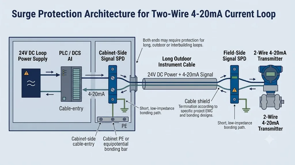
Extérieur ou câble long
Évaluer la protection côté terrain et à l'entrée de l'armoire pour les deux extrémités.
Confirmer : cheminement du câble, limite LPZ, enveloppe, blindage et liaison équipotentielle.
Boucle d'instrumentation Ex i
N'utilisez qu'un SPD approuvé et coordonné pour le circuit intrinsèquement sûr.
Confirmer : Homologation Ex, paramètres d'entité, barrière, mise à la terre et zone d'installation.
Pourquoi il n'existe pas de modèle universel “ 24V 4-20mA ”
Deux boucles ayant la même tension nominale peuvent avoir des sources d'alimentation différentes, des charges d'entrée différentes, des références de mise à la terre différentes, des exigences HART différentes et des conditions de zone dangereuse différentes. Un modèle final ne doit pas être sélectionné à partir de “ 24V, 4-20mA ” seul.
Comment choisir un parasurtenseur de signal 4-20mA
Commencez par le schéma de la boucle plutôt que par le catalogue du SPD. Deux systèmes décrits comme “ 24V 4-20mA ” peuvent utiliser des sources d'alimentation, des références de mise à la terre et des dispositions de conducteurs différentes.
Identifiez le circuit complet
Confirmez si l'instrument est à deux fils alimenté par la boucle, à trois fils ou à quatre fils avec alimentation autonome.
Trouvez la source de l'alimentation de la boucle
Déterminez si l’entrée PLC/DCS, une alimentation externe ou l’instrument de terrain fournit l’alimentation de boucle.
Déterminez la tension nominale la plus élevée
Incluez la tolérance d’alimentation et la tension maximale qui peut rester appliquée en continu aux conducteurs protégés.
Faites correspondre la topologie du circuit du SPD
Choisissez une protection pour une paire flottante, un circuit à référence commune, ou des circuits de signal et de puissance séparés.
Vérifiez la transparence du signal
Examinez la résistance série, la chute de tension, le courant de fuite, la capacité et la compatibilité HART.
Confirmez les conditions d’installation
Précisez un montage sur le terrain ou en armoire, la mise à la terre, la taille des bornes, l’homologation pour zone dangereuse et les exigences environnementales.
Boucles 4-20mA à deux fils, trois fils et quatre fils
Le nombre de conducteurs modifie la façon dont la puissance, le signal et la protection contre les surtensions sont organisés. Une boucle à deux fils utilise normalement la même paire pour l’alimentation et la mesure. Un transmetteur à quatre fils sépare normalement son entrée d’alimentation de sa sortie analogique.
Alimenté par boucle à deux fils
L’alimentation et le signal utilisent la même paire de conducteurs.
- Nécessite généralement une paire flottante protégée.
- La chute de tension du SPD fait partie du budget de tension.
- Confirmez la configuration d’entrée analogique active ou passive.
- Vérifiez HART lorsqu’un transmetteur intelligent est utilisé.
Transmetteur à trois fils
L’instrument dispose généralement d’un positif d’alimentation, d’un commun d’alimentation et d’un conducteur de sortie séparé.
- Le signal peut partager la référence d'alimentation.
- Un SPD à paire flottante peut ne pas convenir au circuit.
- Confirmez quels conducteurs transportent le courant normal.
- Fournissez un schéma de câblage avant la sélection finale.
Autonome à quatre fils
L'instrument dispose d'une entrée d'alimentation séparée et d'une sortie 4-20mA indépendante.
- Évaluez l'alimentation et le signal comme des chemins de surtension distincts.
- La sortie du signal peut être active ou isolée.
- La tension d'alimentation peut différer de la tension du signal.
- Un seul SPD de signal peut ne pas protéger tous les conducteurs.
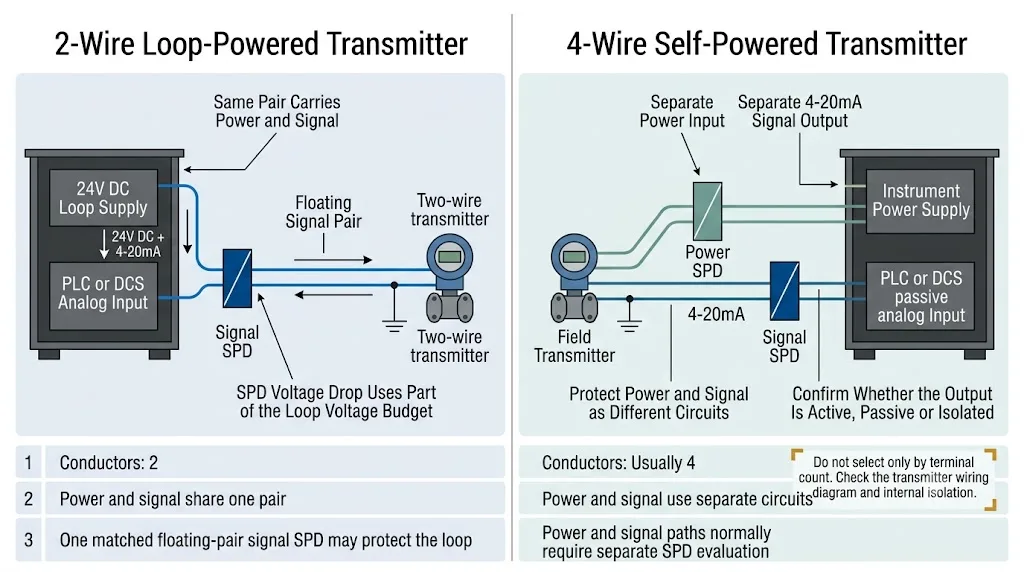
Ne sélectionnez pas le SPD uniquement en fonction du nombre de bornes
Un transmetteur à quatre fils ne nécessite pas forcément un SPD à quatre canaux. Vérifiez d'abord l'entrée d'alimentation, la sortie analogique, l'isolation interne et la référence de mise à la terre.
Boucles 4-20mA actives et passives
Les termes « actif » et « passif » indiquent quel dispositif fournit l'alimentation de boucle. Cela modifie la tension normale et le courant de référence présents sur les conducteurs.
| Configuration | Qui assure l'alimentation de la boucle ? | Connexion typique | Que faut-il confirmer ? |
|---|---|---|---|
| IA active | Entrée analogique d'un automate programmable (PLC) ou d'un système de contrôle distribué (DCS) | La carte IA alimente un émetteur passif à deux fils. | Tension d'alimentation de l'IA et référence de circuit. |
| IA passive | Alimentation de la boucle externe | L'alimentation, l'émetteur et l'IA passive sont connectés en série. | Tolérance d'alimentation, charge AI et référence de mise à la terre. |
| Sortie de l'émetteur actif | L'instrument de terrain | Un instrument autonome pilote une IA passive. | Tension de sortie, limites en mode commun et isolation. |
| Boucle de sortie analogique | Carte AO pour API/DCS ou alimentation externe | AO commande un positionneur de vanne ou un actionneur. | Que l'AO soit en phase de montée ou de descente. |
Une demande se limitant à la mention « SPD 24 V, 4-20 mA » peut s'avérer insuffisante pour déterminer un modèle précis. Un schéma de câblage sommaire, une photo des bornes ou la référence de l'équipement permettent généralement de combler ces informations manquantes.
Quelle tension nominale le parasurtenseur 4-20mA doit-il avoir ?
Sélectionnez la tension SPD à partir de la tension maximale pouvant être maintenue en permanence sur les conducteurs protégés — et non à partir des valeurs de signal de 4 mA ou 20 mA.
La tension maximale de fonctionnement continu du SPD doit être supérieure à la tension normale la plus élevée du circuit, tolérance d'alimentation comprise, tout en restant suffisamment faible pour assurer un niveau de protection efficace.
Un UC plus bas n'est pas forcément synonyme de meilleure qualité
Si la tension de fonctionnement continu du SPD est inférieure à la tension réelle de la boucle, celui-ci peut conduire le courant en fonctionnement normal, augmenter les fuites ou subir une défaillance prématurée.
Un parasurtenseur entraînera-t-il une chute de tension dans une boucle 4-20mA ?
Oui. Un SPD de signal monté en série introduit généralement une résistance ou une autre impédance en série. À 20 mA, cette impédance provoque une chute de tension.
Une faible perte de tension n'entraîne généralement pas d'erreur de mesure de courant proportionnelle. Le transmetteur régule le courant demandé tant qu'une tension suffisante est présente entre ses bornes.
Inclure les charges en série suivantes :
- Charge des entrées analogiques des automates programmables (PLC) ou des systèmes de contrôle distribués (DCS) ;
- résistance de la boucle de câble ;
- les SPD côté armoire et côté terrain ;
- barrières ou isolateurs à sécurité intrinsèque ;
- écrans ou bornes de test alimentés par boucle ;
- marge de sécurité technique.
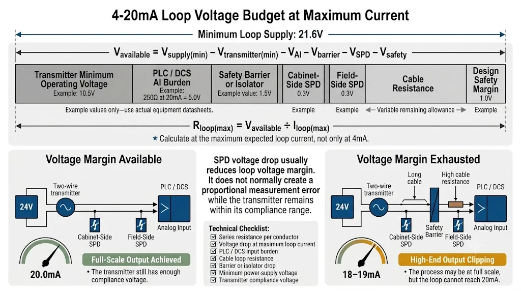
Calculateur de budget de tension de boucle 4-20 mA
Utilisez la tension d'alimentation minimale et le courant de boucle maximal prévu pour effectuer une vérification préliminaire prudente.
Cet exemple conserve une marge de tension positive. Vérifiez les données réelles de l'équipement avant de procéder au choix définitif.
Ce calculateur est un outil d'aide à l'ingénierie préliminaire et ne remplace pas le schéma de boucle définitif ni les fiches techniques des équipements.
Exemple d'interprétation
Si deux SPD provoquent chacun une chute de tension de 0,3 V à 20 mA, ils consomment ensemble 0,6 V. Cela peut être acceptable dans une boucle simple, mais cela revêt une importance particulière dans un circuit long qui comporte également une entrée de 250 Ω et une barrière de sécurité.
Un parasurtenseur de signal peut-il affecter la précision de mesure 4-20mA ?
Un SPD correctement choisi doit rester électriquement transparent en fonctionnement normal.
| Caractéristique | Effet possible | Données relatives aux fournisseurs à vérifier |
|---|---|---|
| Résistance série | Consomme la tension de boucle à courant élevé. | Résistance par conducteur et chute de tension à 20 mA. |
| Courant de fuite | Peut entraîner un décalage dans les circuits de haute précision. | Fuite maximale à l'UC et à la température de fonctionnement. |
| Déséquilibre des conducteurs | Peut réduire la réjection du bruit en mode commun. | Voies de protection adaptées à la paire de signaux. |
| Capacité et bande passante | Cela peut affecter la communication HART. | Compatibilité HART et réponse en fréquence. |
Distinction importante
Une faible chute de tension SPD n'entraîne généralement pas d'erreur de mise à l'échelle proportionnelle. Elle réduit la tension disponible pour le transmetteur. Si la marge devient insuffisante, la boucle peut ne pas atteindre le courant maximal prévu.
Comment choisir un parafoudre compatible HART
Le protocole HART superpose un signal de communication numérique à la boucle classique de 4 à 20 mA. Un SPD peut laisser passer le courant continu tout en atténuant la communication HART.
Le parasurtenseur doit-il être installé au niveau de l'instrument de terrain ou de l'armoire de commande ?
L'emplacement adéquat dépend de l'exposition des câbles, des zones de protection contre la foudre, des points d'entrée dans le bâtiment et des équipements à protéger.
| Condition d’installation | Éléments à prendre en compte | Raison |
|---|---|---|
| Émetteur d'extérieur avec un long câble | Évaluer la protection au niveau du terrain et au niveau de l'accès à l'armoire. | Les deux extrémités contiennent des composants électroniques sensibles. |
| Câble reliant les bâtiments | Assurer la protection à chaque entrée du bâtiment et coordonner la mise à la terre. | Le câble traverse différentes zones équipotentielles. |
| Réservoir, mât ou station de pompage | Utilisez un SPD adapté aux conditions sur site à proximité de l'instrument. | Les sites extérieurs isolés sont davantage exposés. |
| Câblage court à l'intérieur d'un cabinet | Il n'est pas systématiquement nécessaire d'avoir deux SPD. | L'ensemble du circuit peut se trouver dans une seule zone protégée. |
| Boîtier de raccordement sur site | Choisissez entre le point d'entrée de câble et le périmètre de l'équipement. | Le SPD doit se trouver à proximité de la limite de la zone de protection. |
Blindage, mise à la terre sur rail DIN et liaison équipotentielle
Un dispositif SPD de signal nécessite un chemin de décharge à faible impédance. La borne PE, le pied de mise à la terre ou le rail DIN relié doivent être raccordés au système local de liaison équipotentielle en empruntant le chemin le plus court possible.
Sélection d'un parasurtenseur 4-20mA pour zones dangereuses et boucles Ex i
Un SPD de signal industriel standard ne doit pas être installé dans une boucle à sécurité intrinsèque sans vérification préalable.
- Vérifier la conformité aux normes ATEX, IECEx ou aux homologations requises au niveau local ;
- vérifier la zone d'installation et le concept de protection ;
- vérifier les paramètres de tension et de courant maximaux ;
- vérifier la capacité et l'inductance du SPD ;
- coordonner le SPD avec la barrière ou l'isolateur ;
- vérifier la méthode de mise à la terre autorisée ;
- Vérifier les exigences HART ou SIL, le cas échéant.
L'approbation du SPD ne suffit pas à elle seule
L'émetteur, le câble, le SPD, la barrière et la configuration d'installation doivent être considérés comme un seul et même circuit à sécurité intrinsèque.
Ce que fournit l'acheteur et ce que confirme le fournisseur du parasurtenseur
L'acheteur n'a qu'à fournir les informations déjà disponibles. Le fournisseur de la fiche technique du produit (SPD) doit s'en servir pour confirmer les paramètres détaillés du produit.
| Élément de sélection | L'acheteur ou l'ingénieur fournit | Un fournisseur de SPD le confirme |
|---|---|---|
| Topologie en boucle | Informations sur le câblage à deux, trois ou quatre fils, schéma ou photo d'une borne. | Adéquation entre les modes de protection, la disposition des bornes et la référence du circuit. |
| Dispositif d'alimentation | Modèle de carte PLC/DCS, de transmetteur ou d'alimentation électrique, le cas échéant. | Compatibilité avec la tension et le circuit de courant normaux. |
| Tension de service | Tension nominale de boucle, par exemple 24 V CC. | Tension nominale et tension maximale de fonctionnement en continu. |
| Marge de tension | Modèles d'équipements ou données de boucle disponibles. | Résistance en série et chute de tension au courant maximal. |
| Précision des mesures | Exigence particulière en matière de précision, le cas échéant. | Courant de fuite au niveau de l'UC et sur toute la plage de températures de fonctionnement. |
| Performances de protection | Informations relatives à l'exposition à l'intérieur, à l'extérieur, entre deux bâtiments ou dans d'autres contextes. | Niveaux de protection, forme d'onde d'essai et valeurs des courants de surtension. |
| Communication HART | HART requis ou non requis. | Compatibilité HART, capacité et réponse en fréquence. |
| Zone dangereuse | Exigences relatives aux zones à risque et modèle de barrière, le cas échéant. | Champ d'application de l'homologation, paramètres de l'entité et mise à la terre autorisée. |
| Installation | Installation sur site, en armoire ou aux deux extrémités. | Dispositif de fixation, de raccordement, de régulation de la température et de mise à la terre. |
Confirmation du modèle avant un projet ou une commande OEM
LEEYEE peut partir d'informations de base et demander des données supplémentaires uniquement lorsque cela s'avère nécessaire pour la validation finale du modèle.
Processus de confirmation en quatre étapes
Vérifiez le type de boucle, la tension et les équipements raccordés.
Vérifier la puissance apparente, le courant de charge, le niveau de protection et la chute de tension.
Vérifiez les paramètres HART, la protection Ex i, le montage, les bornes et l'environnement.
Valider la fiche technique, l'étiquette, l'emballage et la quantité.
Applications industrielles courantes
Transmetteurs de niveau, de pression, de débit, de pH et de conductivité connectés à des automates programmables (PLC) ou à des panneaux SCADA distants.
Appareils de mesure de pression et de niveau pour usage extérieur, équipés de longs câbles de signal.
Boucles d'instruments DCS dans les installations des secteurs de la chimie, de l'agroalimentaire, du pétrole, du gaz et de l'industrie .
Transmetteurs de niveau et de température à distance installés dans des endroits exposés.
Capteurs analogiques situés à l'extérieur de l'armoire électrique principale ou à proximité de machines de grande taille.
Longues boucles analogiques entre les locaux techniques et les postes de surveillance.
Instruments météorologiques et instruments auxiliaires de processus installés le long de trajets de câbles exposés.
Protection reproductible des entrées analogiques pour les projets d'armoires standardisées.
Erreurs courantes dans la sélection d'un parasurtenseur 4-20mA
Les produits portant la même étiquette peuvent présenter des valeurs de courant nominal (UC), de fuite, de résistance et de niveaux de protection différents.
Un transmetteur à quatre fils peut comporter des circuits distincts pour l'alimentation et la protection contre les surtensions .
Une capacité de résistance aux surtensions élevée ne garantit pas l'adéquation à une boucle présentant une marge de tension limitée.
Le HART dépend également de la réponse en fréquence, de la capacité et de l' impédance en série.
Un instrument de terrain distant peut également être endommagé par l'énergie d'une surtension induite.
De bons paramètres de laboratoire ne peuvent pas compenser un trajet de décharge long ou non isolé.
Les paramètres d'homologation et de l'entité doivent être vérifiés pour l'ensemble du circuit.
Que transmettre pour obtenir une recommandation de parasurtenseur 4-20mA
Envoyez-nous toutes les informations dont vous disposez déjà. Vous n'avez pas besoin de rassembler tous les éléments avant de nous contacter.
Six détails suffisent généralement pour commencer
Vous n'avez pas de schéma de boucle ? Envoyez-nous une fiche technique de l'équipement, une photo des bornes ou un modèle SPD existant. Nous vous aiderons à identifier le circuit.
2 fils, 3 fils ou 4 fils
Par exemple : 24 V CC
Obligatoire ou facultatif
Modèle de transmetteur ou de carte PLC/DCS
Sur site, en armoire ou aux deux extrémités
Quantité, logo et exigences en matière d'emballage
Besoin d'aide pour sélectionner un parasurtenseur de signal 4-20mA ?
Envoyez-nous un schéma de câblage, une photo des bornes, le modèle de l'émetteur ou le modèle SPD existant. LEEYEE vous aidera à identifier la boucle et à déterminer la configuration de protection adaptée.
Questions fréquemment posées
Le même SPD peut-il être utilisé pour toutes les boucles 4-20 mA ?
Non. Les circuits à deux, trois et quatre fils peuvent utiliser différentes sources d'alimentation, différentes configurations de conducteurs et différentes références de mise à la terre.
Un parafoudre signal 24V est-il toujours correct pour une boucle 24V ?
Pas automatiquement. Comparez la tension de fonctionnement continue maximale du SPD avec la tension de boucle normale la plus élevée et la tolérance d’alimentation .
Est-ce que la résistance SPD change la lecture de 4-20mA ?
En règle générale, la résistance SPD consomme la tension de boucle plutôt que de générer une erreur de mise à l'échelle proportionnelle. Si la marge de tension devient insuffisante, la boucle peut ne pas atteindre le courant de pleine échelle .
Un boucle 4-20mA doit-elle être protégée à ses deux extrémités ?
La protection aux deux extrémités s'avère souvent utile pour les circuits extérieurs, longue distance ou reliant plusieurs bâtiments. Elle n'est pas obligatoire pour toutes les courtes connexions internes.
Un SPD standard de 4-20 mA peut-il transmettre une communication HART ?
Uniquement si sa capacité, sa réponse en fréquence et son impédance en série sont adaptées. Il convient de vérifier expressément la compatibilité HART.
Un transmetteur à quatre fils a-t-il besoin de deux SPD ?
Il peut nécessiter une protection distincte pour son entrée d'alimentation et sa sortie de signal. La configuration finale dépend du câblage et de l'isolation interne.
Le blindage du câble peut-il remplacer la connexion à la terre de l'SPD ?
Non. La mise à la terre du blindage et la mise à la terre de protection du SPD remplissent des fonctions connexes mais distinctes.
Quelle norme s'applique aux SPD du signal 4-20 mA ?
La norme CEI 61643-21 définit les exigences et les essais applicables aux parafoudres pour réseaux de signalisation. La norme CEI 61643-22 présente les principes de sélection et d'application.
Références techniques
- IEC, IEC 61643-21:2025 — Exigences et méthodes d'essai pour les dispositifs de protection contre les surtensions (SPD) raccordés aux réseaux de télécommunications et de signalisation .
- IEC, IEC 61643-22:2015 — Principes de sélection et d'application .
- FieldComm Group, Guide d'utilisation de HART .
- Texas Instruments, Conception de référence d'un transmetteur 4-20 mA à alimentation par boucle et à faible coût .
- LEEYEE, Guide sur la protection contre les surtensions des automates programmables (PLC) .
