
La protection contre les surtensions Modbus signifie généralement protéger le circuit de communication RS485 utilisé par Modbus RTU. Installez un SPD de ligne de signal compatible là où un câble RS485 exposé entre dans le PLC, la passerelle ou l'enceinte de l'appareil de terrain. Pour les liaisons extérieures ou inter-bâtiments, évaluez la protection à chaque extrémité. Modbus TCP utilise un SPD Ethernet au lieu d'un SPD RS485.
L'objectif réel de la protection est le transceiver RS485 à l'intérieur du PLC, RTU, compteur d'énergie, passerelle ou instrument de terrain distant—et pas simplement les deux conducteurs dans le câble de communication.
Ce guide explique où l'énergie de surtension entre dans un système Modbus, où les SPD doivent être installés, si la protection peut affecter la communication, et ce que les acheteurs de projets ou OEM doivent confirmer avant de commander.
Table des matières
Où un protecteur contre les surtensions Modbus doit-il être installé ?
Identifiez l'interface conductrice et la limite de zone de protection avant de sélectionner le SPD.
Modbus RTU et RS485 sont liés, mais ce ne sont pas les mêmes.
Modbus définit les messages échangés par les dispositifs industriels. RS485 définit l'interface électrique utilisée pour transmettre ces messages sur une ligne série équilibrée. Modbus TCP utilise Ethernet et TCP/IP pour transmettre la communication Modbus. [1] [2]
Le mot “ Modbus ” seul n'est pas suffisant pour la sélection des SPD. Identifiez d'abord si le circuit conducteur est RS485, Ethernet, alimentation auxiliaire ou une autre interface physique.
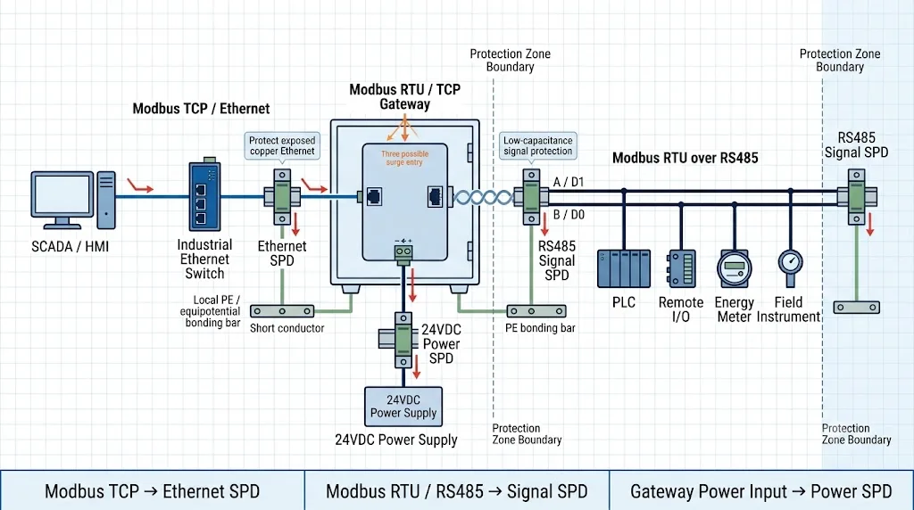
Pourquoi les longues lignes de communication Modbus RS485 sont-elles exposées aux surtensions ?
Le signalement différentiel RS485 offre une immunité utile contre le bruit, mais il ne rend pas le transciever immunisé contre les tensions induites par la foudre, les transitoires de commutation ou les différences de potentiel excessives entre les zones de mise à la terre.
Longs itinéraires en cuivre
De longs câbles de communication offrent un chemin de couplage plus large pour les champs électromagnétiques produits par la foudre et les commutations.
Équipement extérieur
Les stations de pompage, les compteurs d'énergie, les dispositifs de surveillance solaire et les contrôleurs de terrain utilisent souvent des itinéraires de câbles exposés.
Différentes zones de mise à la terre
Des armoires ou des bâtiments peuvent connaître différents potentiels locaux de terre lors d'événements de foudre ou de défauts électriques.
Moteurs et charges de commutation
Les contacteurs, moteurs, soudeurs et installations de variateurs de fréquence peuvent créer des perturbations autour d'un câblage de communication mal séparé.
Multiples chemins de câbles
Un PLC ou une passerelle peut être connecté à l'alimentation CA, à l'alimentation 24VDC, à RS485, à Ethernet et à des signaux de terrain en même temps.
Échec du port de communication
Un transceiver RS485 endommagé peut arrêter la communication même lorsque le CPU du PLC et l'alimentation semblent toujours opérationnels.
Le câblage en paire torsadée aide à contrôler les interférences normales. La protection contre les surtensions fournit un chemin contrôlé pour le courant transitoire. Un routage, un câblage, une isolation et une terminaison corrects sont toujours nécessaires.
Où un SPD RS485 doit-il être installé dans un réseau Modbus RTU ?
Installez le SPD là où un câble de terrain exposé entre dans le coffret, l'enceinte, le bâtiment ou la zone de protection contenant l'équipement sensible. Le câble de terrain doit atteindre le SPD avant d'être acheminé à côté du PLC, de la passerelle ou du module de communication.
| Scénario de réseau Modbus | Position SPD recommandée | Protéger les deux extrémités ? | Raison technique |
|---|---|---|---|
| Lien court à l'intérieur d'un coffret relié | Un SPD de ligne externe séparé peut ne pas être nécessaire après l'évaluation des risques sur site. | Généralement pas | Le câble est court et reste à l'intérieur d'une zone équipotentielle. |
| Coffret PLC vers un instrument intérieur distant | À l'entrée du câble du coffret PLC et près de l'équipement distant lorsque le trajet traverse des zones exposées. | Souvent approprié | La ligne peut traverser de longs trajets, des zones d'alimentation ou des points de mise à la terre locaux séparés. |
| Compteur extérieur, station de pompage ou RTU distante | À l'entrée du panneau de contrôle principal et à l'entrée de l'enveloppe distante. | Généralement oui | Les deux extrémités sont connectées à un équipement exposé et à des systèmes de mise à la terre locaux. |
| Câble cuivré RS485 entre les bâtiments | À l'entrée du câble de chaque bâtiment ou zone de protection. | Oui | Les différences de potentiel de terre et l'exposition à la foudre peuvent affecter chaque extrémité. |
| Passerelle connectée à un tronc de terrain | À l'entrée du câble RS485 exposé à côté de la passerelle et à l'enveloppe distante si nécessaire. | Dépend de l'exposition | Le côté RS485 doit être évalué indépendamment de l'Ethernet et de l'alimentation. |
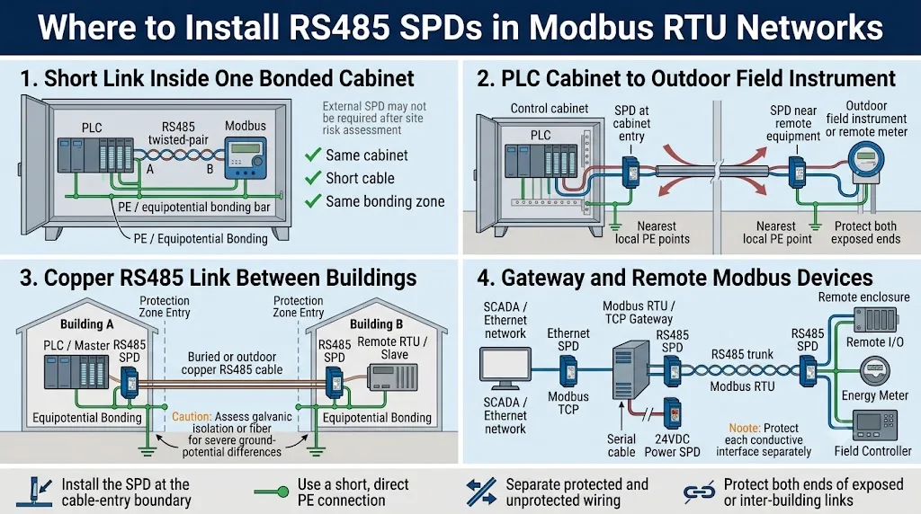
Lorsque le câble de terrain non protégé traverse le boîtier avant d'atteindre le parafoudre, l'énergie de surtension a déjà pénétré dans l' espace protégé et peut se propager vers le câblage voisin.
Comment les lignes Modbus RTU A/B ou D0/D1 doivent-elles passer par le SPD ?
Le SPD de signal RS485 est généralement installé en série. Le câble de terrain non protégé se raccorde au côté LINE ou IN. La sortie protégée se raccorde à l'automate programmable, au RTU, au compteur, à la passerelle ou au contrôleur de terrain.
Dans la convention officielle de nommage des lignes série Modbus, D1 correspond à B/B′ et D0 correspond à A/A′. Les fabricants d’équipements n’utilisent pas toujours les lettres A et B de manière cohérente ; il convient donc de vérifier le manuel de chaque appareil et de veiller à maintenir la continuité des conducteurs à travers le SPD. [1]
Raccordez les conducteurs RS485 d'entrée dénudés aux bornes portant les inscriptions LINE, FIELD ou IN, conformément au schéma du SPD.
Reliez les bornes « OUT » ou « EQUIPMENT » protégées au port de communication en utilisant le câblage le plus court possible.
Protégez la paire symétrique D0/D1 et vérifiez comment le conducteur commun du réseau est pris en compte dans la conception globale du système.
Vérifiez que le SPD ou la combinaison de SPDs offre un nombre suffisant de canaux pour les paires d'émission et de réception.
Le SPD ne remplace pas les résistances de terminaison de ligne ni les résistances de polarisation du réseau.
Pour le câblage borne par borne, le choix entre le câblage à deux fils et celui à quatre fils ainsi que les paramètres détaillés des signaux, voir le Guide de câblage et de sélection des SPD RS485.
Le blindage de câble, le commun de signal et le PE du SPD ne sont pas le même conducteur.
Chaque connexion remplit une fonction différente. Les combiner sans avoir élaboré de schéma de système peut entraîner des défauts de communication ou un chemin de décharge des surtensions inefficace.
Blindage du câble
Le blindage permet de contrôler le couplage électromagnétique autour de la paire de communication. Son mode de raccordement doit respecter les spécifications de conception CEM de l'équipement et du projet.
Signal commun
Le conducteur « Common » sert de conducteur de référence associé à la paire symétrique RS485. Il ne correspond pas nécessairement au conducteur PE ni au blindage du câble.
SPD PE ou conducteur de mise à la terre
Il s'agit du chemin de dérivation prévu pour les courants de surtension vers le système local de liaison équipotentielle. Veillez à ce qu'il soit court et direct.
Le guide sur les liaisons série Modbus prend comme référence l'utilisation d'un câble blindé et une connexion de terre de protection à une seule extrémité. La mise à la terre finale dépend toutefois de l'armoire, du bâtiment, de la méthode d'isolation, de l'environnement CEM et des instructions relatives à l'équipement. [1]
Un SPD limite les surtensions transitoires. L'isolation galvanique permet de gérer les courants provoqués par des différences de potentiel par rapport à la terre, qu'elles soient permanentes ou temporaires. Les liaisons inter-bâtiments exposées peuvent nécessiter les deux, ou une conversion à la fibre optique.
Un protecteur de surtension RS485 affectera-t-il la communication Modbus ?
Un SPD de signal correctement choisi ne devrait pas perturber de manière significative la liaison Modbus RTU visée. Un dispositif mal adapté peut ajouter de la capacité, une résistance en série ou une perte d'insertion, et réduire la marge de signal d’un réseau déjà faible.
| Paramètres | Pourquoi c'est important | Symptôme possible | Confirmation de l'acheteur |
|---|---|---|---|
| Tension de fonctionnement maximale continue | Le SPD doit rester inactif lorsque la tension normale la plus élevée est présente sur le circuit. | Fuites, déformations, échauffement ou vieillissement prématuré | Vérifiez la tension réelle sur chaque conducteur protégé. |
| Niveau de protection de la tension | La tension résiduelle doit être adaptée au port de communication protégé. | Le SPD fonctionne toujours, mais l'émetteur-récepteur est toujours endommagé. | Indiquez le mode de test, la forme d'onde, le courant et la valeur. |
| Capacité de ligne | Une capacité excessive peut ralentir les transitions de signal et réduire la marge de transmission. | Erreurs CRC, délais d'attente ou instabilité à des débits en bauds élevés | Demander les données de capacité dans des conditions définies. |
| Résistance et perte d'insertion | Une impédance supplémentaire peut atténuer le signal différentiel. | Portée réduite, nœuds distants instables ou vitesse utile inférieure | Vérifier la résistance, la perte d'insertion et le débit de données. |
| Nombre de canaux protégés | Les systèmes à deux fils et à quatre fils nécessitent des configurations de canaux différentes. | Câblage incorrect ou conducteurs non protégés | Veuillez envoyer le schéma des bornes avant la validation du modèle. |
| Raccordement PE | Un câble de raccordement long ou indirect augmente la tension transitoire au niveau de l'installation. | Pannes répétées du port de communication après des pics de tension | Vérifiez la barre en PE locale et sa position de montage. |
La tension d'alimentation du tableau de commande n'est pas nécessairement égale à la tension présente sur les conducteurs de communication RS485. Vérifiez le circuit à protéger et sélectionnez séparément la protection de l'alimentation et celle des signaux.
Symptôme probablement lié à une poussée
Le port de communication tombe en panne après un orage, le même nœud distant doit être remplacé à plusieurs reprises, ou plusieurs appareils tombent en panne au niveau de la même jonction de câble.
Symptôme susceptible d'être lié à l'intégrité du signal
Des erreurs apparaissent dès l'installation, s'aggravent à mesure que le débit en bauds augmente, ou affectent les appareils situés à l'extrémité d'une longue ligne.
Modbus TCP nécessite une protection Ethernet, pas un SPD RS485.
La communication Modbus TCP s'effectue via Ethernet TCP/IP. Un SPD RS485 à deux fils ne peut pas protéger une liaison Ethernet RJ45. Le SPD Ethernet doit être adapté à la vitesse du réseau, au connecteur, à la catégorie de câble, au blindage et à toute alimentation électrique acheminée par le câble. [2]
Côté RS485
Utilisez un SPD de ligne de signal adapté au circuit Modbus RTU, à la tension et aux conditions d'installation.
Côté Ethernet
Utilisez un SPD Ethernet ou RJ45 adapté à la vitesse, au type de câble, au blindage et aux exigences en matière de PoE.
Alimentation électrique de la passerelle
Évaluez séparément l’alimentation 24 V CC ou CA et utilisez le parafoudre de puissance correspondant si nécessaire.
La norme CEI 61643-21:2025 porte sur les dispositifs de protection contre les surtensions (SPD) destinés aux réseaux de télécommunications et de signalisation, y compris les réseaux pouvant également fournir de l'énergie sur la même ligne, tels que le PoE. [3]
Liste de vérification pour la sélection du protecteur Modbus destinée aux acheteurs B2B.
Un fournisseur ne peut pas choisir le SPD adapté en se basant uniquement sur les indications « Modbus » ou « RS485 ». Veuillez fournir les informations relatives à l'interface physique, aux limites électriques, au tracé du câblage, aux conditions de mise à la terre et aux données de test requises avant d'approuver un modèle.
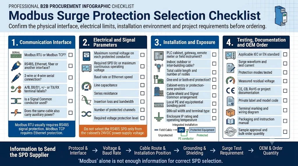
Demandez au fournisseur de préciser la forme d'onde d'essai, le mode de couplage, le mode de protection et les conditions de mesure de la tension résiduelle. La norme CEI 61643-21 définit les exigences et les méthodes d'essai applicables aux SPD utilisés dans les réseaux de télécommunications et de signalisation. [3]
Protecteur de signal de données RS485 LY10.
Le LY10 est un parafoudre de signal monté sur rail DIN destiné aux circuits RS485, de télémétrie, d'automate programmable, de capteurs et de communication industrielle. Il est installé en série en amont de l'équipement à protéger.
Considérez le modèle LY10 comme un modèle potentiel plutôt que de le choisir uniquement sur la base du terme « Modbus ». Vérifiez la tension du circuit, la disposition des conducteurs, le débit de données, le tracé du câble et les conditions de mise à la terre avant de passer commande.
Une armoire qualifiée de « système 24 V » ne nécessite pas systématiquement un SPD RS485 24 V. Vérifiez la tension maximale présente sur les conducteurs réels acheminés via le SPD de signal.
Six erreurs courantes de protection contre les surtensions Modbus.
Les câbles RS485, Ethernet et de terrain à distance constituent des voies de conduction distinctes pour les surtensions.
La tension d'alimentation de l'armoire ne détermine pas automatiquement la tension du circuit de communication.
Les liaisons extérieures ou entre bâtiments nécessitent souvent une protection au niveau des deux points d'entrée de la zone de protection.
Le réseau Ethernet nécessite une protection adaptée à son connecteur, à ses paires de câbles et à ses performances de transmission.
Un conducteur de liaison long, enroulé ou indirect augmente la tension résiduelle installée.
Des conducteurs inversés, des raccordements défectueux, de longs tronçons et une topologie inadaptée peuvent déjà rendre le réseau instable.
FAQ sur la protection contre les surtensions Modbus.
Tous les réseaux Modbus RTU ont-ils besoin d'un SPD RS485 ?
Non. Un court câble de raccordement interne à l'intérieur d'une armoire reliée présente un risque différent de celui d'un long câble extérieur ou reliant deux bâtiments. Évaluez l'exposition, les zones de mise à la terre, la valeur des équipements et la disponibilité requise.
Un câble Modbus RS485 doit-il être protégé à chaque extrémité ?
La protection aux deux extrémités est généralement prévue pour les liaisons extérieures, de longue distance, entre bâtiments ou reliant des zones de mise à la terre distinctes. Un câble interne court peut ne pas nécessiter deux parafoudres.
Un SPD RS485 peut-il provoquer des erreurs CRC ou des délais d'attente ?
Un SPD mal adapté peut être à l'origine d'erreurs dues à une capacité, une résistance ou une perte d'insertion excessives, ou encore à un câblage incorrect. Vérifiez également la polarité, la terminaison, les dérivations et la topologie.
D1 correspond-il à A ou à B ?
Le guide officiel sur les liaisons série Modbus attribue la broche D1 aux broches B/B′ et la broche D0 aux broches A/A′. Certains fabricants utilisent les désignations A/B différemment, il convient donc de consulter les manuels des deux équipements.
Un dispositif de protection contre les surtensions (SPD) alimenté en 24 V CC peut-il protéger une ligne RS485 ?
Pas systématiquement. Les SPD de puissance et les SPD de signal présentent des exigences différentes en matière de tension, de courant, de capacité, de transmission et de raccordement .
Quel protecteur faut-il utiliser pour Modbus TCP ?
Utilisez un SPD pour ligne de données Ethernet adapté à la vitesse du réseau, au connecteur, à la catégorie de câble, au blindage et à toute exigence en matière de PoE.
Un SPD RS485 remplace-t-il la résistance de terminaison ?
Non. Le SPD limite les surtensions transitoires. Les composants de terminaison et de polarisation assurent l'intégrité du signal et gèrent les états de repos du bus.
Quelles informations faut-il fournir avant de passer commande ?
Veuillez nous communiquer les informations suivantes : interface, schéma de câblage, schéma des bornes, tension du circuit, débit en bauds, longueur de câble, nombre de nœuds, position d'installation, méthode de mise à la terre, exigences de test et détails de la commande OEM.
Poursuivre avec la sélection au niveau de l'interface et du cabinet.
Normes et sources principales.
Le choix final doit être vérifié au regard du cahier des charges le plus récent du projet, du manuel d'utilisation de l'équipement, de la fiche technique approuvée du produit et des exigences locales applicables.
- Organisation Modbus, Guide de spécification et de mise en œuvre de MODBUS sur ligne série V1.02. Traite des interfaces à deux fils et à quatre fils, de la nomenclature D0/D1, de la terminaison, de la polarité, du blindage et du câblage.
- Organisation Modbus, Guide de mise en œuvre de la communication MODBUS sur TCP/IP, version 1.0b. Décrit la communication Modbus via Ethernet TCP/IP et la mise en œuvre d'une passerelle .
- Commission électrotechnique internationale, IEC 61643-21 : 2025. Exigences et méthodes d'essai applicables aux dispositifs de protection contre les surtensions (SPD) raccordés aux réseaux de télécommunications et de signalisation.
- Commission électrotechnique internationale, IEC 61643-22:2015. Principes de sélection, d'exploitation, d'implantation et de coordination des SPD du réseau de signalisation.
- LEEYEE, Dispositif de protection contre les surtensions des signaux de données LY10. Paramètres actuels des produits et informations d'installation publiés.
Envoyer le chemin de communication Modbus complet—pas seulement “ RS485 ”.”
Veuillez fournir le modèle de l'appareil, le schéma du terminal, la tension réelle du circuit, le débit en bauds, la longueur du câble, le nombre de nœuds, les emplacements d'installation, le schéma de mise à la terre, les données de test requises et la quantité commandée prévue. LEEYEE peut vous aider à déterminer quelles interfaces nécessitent une protection RS485, Ethernet ou côté alimentation.
