
Guía de selección de Instrumentación Industrial
Seleccionando un protector contra sobretensiones de 4-20mA no es solo una cuestión de corriente de sobretensión. El SPD de señal debe coincidir con el voltaje del lazo, circuito de dos hilos o cuatro hilos, disposición de alimentación del transmisor, entrada de PLC o DCS, comunicación HART y el voltaje disponible en todo el lazo de corriente completo.
Índice
Respuesta rápida: ¿Qué SPD debe utilizarse para un bucle de 4-20mA?
Para un transmisor típico de 24V de dos hilos y alimentado por el lazo, utiliza un SPD de señal diseñado para un lazo de corriente de dos conductores flotante.
Confirma que el voltaje máximo de funcionamiento continuo del SPD esté por encima del voltaje máximo del lazo normal. Luego verifica la resistencia en serie o caída de voltaje en la corriente máxima del lazo, corriente de fuga, nivel de protección, método de conexión a tierra y compatibilidad HART.
Un transmisor de cuatro hilos normalmente tiene una entrada de alimentación separada y salida de 4-20mA. Sus conductores de alimentación y conductores de señal deben ser evaluados como circuitos diferentes. Un SPD de señal de dos hilos puede no proteger el instrumento completo.
Configuraciones de protección recomendadas
Utiliza esta matriz para la planificación inicial. La confirmación final del modelo aún requiere información básica del lazo y del equipo.
transmisor de 2 hilos, 24V
Utiliza un SPD de señal emparejado para el par de lazo de corriente flotante.
Confirma: UC, resistencia en serie, corriente de fuga y protección línea a línea/tierra.
lazo HART de 2 hilos
Utiliza un SPD de señal de 4-20mA con compatibilidad HART explícita.
Confirma: capacitancia, respuesta de frecuencia, lazo impedancia y caída de voltaje.
transmisor de 4 hilos
Evalúa la entrada de alimentación del instrumento y la salida de 4-20mA por separado.
Confirma: voltaje de alimentación, tipo de salida, aislamiento y referencia de señal.
Al aire libre o cable largo
Evaluar la protección en el lado del campo y la entrada del armario en ambos extremos.
Confirma: ruta del cable, límite de LPZ, recinto, blindaje y puesta a tierra.
Bucle de instrumento Ex i
Utilizar solo un SPD aprobado y coordinado para el circuito intrínsecamente seguro.
Confirma: Aprobación Ex, parámetros de entidad, barrera, puesta a tierra y zona de instalación.
Por qué no existe un modelo universal “24V 4-20mA”
Dos bucles con el mismo voltaje nominal pueden tener diferentes fuentes de alimentación, cargas de entrada, referencias de tierra, requisitos HART y condiciones de área peligrosa. Un modelo final no debe seleccionarse solo de “24V, 4-20mA”.
Cómo seleccionar un SPD de señal de 4-20mA
Comience con el diagrama del lazo en lugar del catálogo SPD. Dos sistemas descritos como “24V 4-20mA” pueden utilizar diferentes fuentes de energía, referencias de tierra y arreglos de conductores.
Identificar el circuito completo
Confirmar si el instrumento es alimentado por el lazo de dos hilos, tres hilos o cuatro hilos autoalimentado.
Encontrar la fuente de energía del lazo
Determine si la entrada del PLC/DCS, una fuente externa o el instrumento de campo proporciona energía al lazo.
Determine el voltaje normal más alto
Incluya la tolerancia de suministro y el voltaje máximo que puede permanecer continuamente en los conductores protegidos.
Coincidir la topología del circuito del SPD
Elija la protección para un par flotante, un circuito de referencia común o circuitos de señal y potencia separados.
Verifique la transparencia de la señal
Revise la resistencia en serie, la caída de voltaje, la corriente de fuga, la capacitancia y la compatibilidad con HART.
Confirme las condiciones de instalación
Especifique el montaje en campo o en gabinete, conexión a tierra, tamaño de terminal, aprobación para áreas peligrosas y requisitos ambientales.
Bucles de 4-20mA de dos hilos, tres hilos y cuatro hilos
El número de conductores cambia cómo se organizan la energía, la señal y la protección contra sobrevoltajes. Un lazo de dos hilos normalmente utiliza el mismo par para la energía y la medición. Un transmisor de cuatro hilos normalmente separa su entrada de energía de su salida analógica.
Bucle de dos hilos alimentado por energía
La energía y la señal utilizan el mismo par de conductores.
- Normalmente requiere un par flotante protegido.
- La caída de voltaje del SPD forma parte del presupuesto de voltaje.
- Confirme la disposición AI activa o pasiva.
- Verifique HART cuando se use un transmisor inteligente.
Transmisor de tres hilos
El instrumento normalmente tiene positivo de suministro, común de suministro y un conductor de salida separado.
- La señal puede compartir la referencia de suministro.
- Un SPD de par flotante puede no coincidir con el circuito.
- Confirme qué conductores transportan corriente normal.
- Proporcione un diagrama de cableado antes de la selección final.
Autopropulsado de cuatro hilos
El instrumento tiene una entrada de alimentación separada y una salida independiente de 4-20 mA.
- Evalúe la potencia y la señal como caminos de sobrecarga separados.
- La salida de señal puede ser activa o aislada.
- La tensión de alimentación puede diferir de la tensión de señal.
- Un SPD de señal puede no proteger todos los conductores.
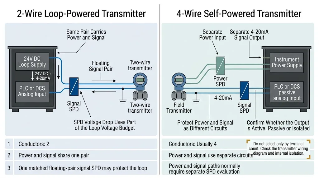
No seleccione el SPD solo por el número de terminales
Un transmisor de cuatro hilos no requiere automáticamente un SPD de señal de cuatro canales. Confirme primero la entrada de alimentación, la salida analógica, el aislamiento interno y la referencia de puesta a tierra.
Bucles de 4-20mA activos y pasivos
“Activo” y “pasivo” describen qué dispositivo suministra la alimentación del lazo. Esto modifica el voltaje y la referencia normales presentes en los conductores.
| Disposición | ¿Quién suministra la alimentación del lazo? | Conexión típica | ¿Qué debe confirmarse? |
|---|---|---|---|
| AI activo | Entrada analógica PLC o DCS | La tarjeta AI alimenta un transmisor pasivo de dos hilos. | Tensión de alimentación de AI y referencia del circuito. |
| AI pasiva | Fuente de alimentación externa del lazo | La fuente de alimentación, el transmisor y la IA pasiva están conectados en serie. | Tolerancia de suministro, carga de IA y referencia de puesta a tierra. |
| Salida del transmisor activo | El instrumento de campo | Un instrumento autoalimentado controla una IA pasiva. | Tensión de salida, límites de modo común y aislamiento. |
| Lazo de salida analógica | Tarjeta AO del PLC/DCS o fuente externa | La AO controla un posicionador de válvula o un actuador. | Si la AO suministra o absorbe corriente. |
Una solicitud que solo diga “24V, 4-20mA SPD” puede no ser suficiente para un modelo final. Un diagrama básico de cableado, una foto de los bornes o el modelo del equipo normalmente pueden resolver la información que falta.
¿Qué clasificación de voltaje debe tener el SPD de 4-20mA?
Seleccione el SPD de señal a partir de la tensión más alta que pueda permanecer continuamente en los conductores protegidos, no de los valores de señal de 4mA o 20mA.
La tensión máxima de funcionamiento continuo del SPD debe ser superior a la tensión normal más alta del circuito, incluida la tolerancia de la alimentación, y a la vez lo bastante baja para proporcionar un nivel de protección útil.
Un UC más bajo no es automáticamente mejor
Si la tensión de trabajo continua del SPD está por debajo de la tensión real del lazo, puede conducir durante el funcionamiento normal, aumentar la fuga o fallar prematuramente.
¿Un SPD causará caída de voltaje en un bucle de 4-20mA?
Sí. Un SPD de señal conectado en serie normalmente introduce resistencia u otra impedancia en serie. A 20mA, esa impedancia crea una caída de tensión.
Una pequeña pérdida de tensión normalmente no genera un error de medición de corriente proporcional. El transmisor regula la corriente solicitada mientras permanezca tensión suficiente en sus bornes.
Incluya las siguientes cargas en serie:
- Carga de entrada analógica del PLC o DCS;
- resistencia del lazo del cable;
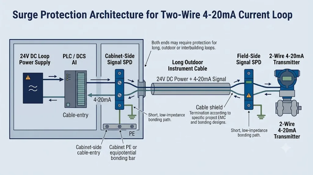
- SPD del lado del armario y del lado de campo;
- barreras o aisladores de seguridad intrínseca;
- pantallas alimentadas por bucle o terminales de prueba;
- margen de seguridad de ingeniería.
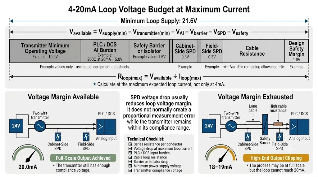
calculadora de presupuesto de tensión de bucle de 4-20 mA
Utilice el voltaje de alimentación mínimo y la corriente de bucle máxima esperada para una comprobación preliminar conservadora.
El ejemplo conserva un margen de tensión positivo. Confirme los datos reales del equipo antes de la selección final.
Esta calculadora es una herramienta de ingeniería preliminar y no sustituye al esquema de bucle ni a las hojas de datos del equipo.
Interpretación de ejemplo
Si dos SPD tienen cada uno una caída de 0,3 V a 20 mA, consumen 0,6 V en conjunto. Esto puede ser aceptable en un bucle simple, pero es importante en un circuito largo que también contiene una entrada de 250 Ω y una barrera de seguridad.
¿Un SPD de señal puede afectar la precisión de medición de 4-20mA?
Un SPD seleccionado correctamente debe permanecer eléctricamente transparente durante el funcionamiento normal.
| Característica | Efecto posible | Datos del proveedor para verificar |
|---|---|---|
| Resistencia en serie | Consume voltaje de bucle a alta corriente. | Resistencia por conductor y caída de tensión a 20mA. |
| Corriente de fuga | Puede añadir compensación en circuitos de alta precisión. | Fuga máxima a UC y temperatura de funcionamiento. |
| Desequilibrio del conductor | Puede reducir el rechazo de ruido en modo común. | Rutas de protección adaptadas para el par de señales. |
| Capacitancia y ancho de banda | Puede afectar la comunicación HART. | Compatibilidad HART y respuesta en frecuencia. |
Distinción importante
Una pequeña caída de tensión en el SPD normalmente no genera un error de escala proporcional. Reduce la tensión disponible para el transmisor. Si el margen resulta insuficiente, es posible que el bucle no alcance la corriente de gama alta esperada.
Cómo seleccionar un protector contra sobretensiones compatible con HART
HART superpone una señal de comunicación digital al bucle convencional de 4-20 mA. Un SPD puede permitir el paso de corriente continua, pero aun así atenuar la comunicación HART.
¿Debería instalarse el SPD en el instrumento de campo o en el armario de control?
La posición correcta depende de la exposición del cable, las zonas de protección contra rayos, los puntos de entrada al edificio y el equipo que requiere protección.
| Condición de instalación | Consideración recomendada | Razón |
|---|---|---|
| Transmisor para exteriores con cable largo | Evalúe la protección del lado de campo y de la entrada al gabinete. | Ambos extremos contienen componentes electrónicos sensibles. |
| Cable entre edificios | Proteja en cada entrada del edificio y coordine la conexión equipotencial. | El cable atraviesa diferentes zonas equipotenciales. |
| Tanque, mástil o estación de bombeo | Utilice un SPD compatible con el campo cerca del instrumento. | Las ubicaciones remotas al aire libre enfrentan una mayor exposición. |
| Cableado corto dentro de un gabinete | No se requieren automáticamente dos SPD. | El circuito completo puede permanecer en una zona protegida. |
| Caja de conexiones de campo | Elija la entrada de cable o el límite del equipo. | El SPD debe estar cerca del límite de la zona de protección. |
Apantallamiento, conexión a tierra en riel DIN y unión equipotencial
Un SPD de señal requiere una trayectoria de descarga de baja impedancia. El terminal PE, la base de conexión a tierra o el riel DIN vinculado deben conectarse al sistema de conexión equipotencial local mediante la ruta más corta posible.
Selección de SPD de 4-20mA para áreas peligrosas y bucles Ex i
Un SPD de señal industrial estándar no debe colocarse en un bucle de seguridad intrínseca sin previa verificación.
- Confirme la aprobación ATEX, IECEx o la requerida localmente;
- confirme la zona de instalación y el concepto de protección;
- verifique los parámetros máximos de voltaje y corriente;
- verifique la capacitancia e inductancia del SPD;
- coordine el SPD con la barrera o el aislador;
- confirme el método de conexión a tierra permitido;
- Verifique los requisitos HART o SIL cuando corresponda.
La aprobación del SPD por sí sola no es suficiente.
El transmisor, el cable, el SPD, la barrera y la disposición de la instalación deben evaluarse como un único circuito de seguridad intrínseca.
Qué proporciona el comprador y qué confirma el proveedor de SPD
El comprador solo necesita proporcionar la información que ya está disponible. El proveedor del SPD debe utilizarla para confirmar los parámetros detallados del producto.
| Artículo de selección | El comprador o ingeniero proporciona | El proveedor de SPD confirma |
|---|---|---|
| Topología de bucle | Información, plano o foto de los terminales de dos, tres o cuatro hilos. | Modos de protección, disposición de terminales y referencia de circuito correspondientes. |
| Disposición de alimentación | Tarjeta PLC/DCS, transmisor o modelo de fuente de alimentación, si está disponible. | Idoneidad para la tensión del circuito normal y la trayectoria de la corriente. |
| Tensión de trabajo | Tensión nominal de bucle, por ejemplo 24V CC. | Tensión nominal y tensión máxima de funcionamiento continuo. |
| Margen de tensión | Modelos de equipo o datos de bucle disponibles. | Resistencia en serie y caída de tensión a corriente máxima. |
| Precisión de la medición | Requisito de precisión especial, cuando corresponda. | Corriente de fuga en UC y en todo el rango de temperatura de funcionamiento. |
| Rendimiento de la protección | Información sobre exposición en interiores, exteriores, entre edificios u otras. | Niveles de protección, forma de onda de prueba y valores de corriente de sobretensión. |
| Comunicación HART | HART requerido o no requerido. | Compatibilidad, capacitancia y respuesta de frecuencia HART. |
| Área peligrosa | Requisito de área peligrosa y modelo de barrera si está disponible. | Alcance de la aprobación, parámetros de la entidad y puesta a tierra permitida. |
| Instalación | Instalación en campo, en gabinete o en ambos extremos. | Disposición de montaje, terminales, temperatura y conexión a tierra. |
Confirmación del modelo antes de un proyecto u orden OEM
LEEYEE puede comenzar con información básica y solicitar datos adicionales solo cuando sea necesario para la confirmación final del modelo.
Proceso de confirmación de cuatro pasos
Comprobar el tipo de bucle, el voltaje y el equipo conectado.
Confirme la UC, la carga actual, el nivel de protección y la caída de tensión.
Compruebe HART, Ex i, el montaje, los terminales y el entorno.
Aprobar la ficha técnica, la etiqueta, el embalaje y la cantidad.
Aplicaciones industriales típicas
Transmisores de nivel, presión, caudal, pH y conductividad conectados a paneles PLC o SCADA remotos.
Instrumentos de presión y nivel para exteriores con cables de señal de larga distancia.
Bucles de instrumentación DCS en instalaciones químicas, alimentarias, de petróleo, gas y manufactura.
Transmisores remotos de nivel y temperatura en ubicaciones expuestas.
Sensores analógicos fuera del gabinete de control principal o cerca de maquinaria pesada.
Bucles analógicos largos entre salas de instalaciones y paneles de monitoreo.
Instrumentos meteorológicos y de procesos auxiliares en rutas de cables expuestas.
Protección de entrada analógica repetible para proyectos de armarios estandarizados.
Errores comunes en la selección de SPD de 4-20mA
Los productos con la misma etiqueta pueden tener diferentes niveles de UC, fugas, resistencia y protección.
Un transmisor de cuatro hilos puede tener rutas de sobretensión separadas para la alimentación y la señal.
Una alta capacidad de sobretensión no garantiza la idoneidad para un bucle con un margen de voltaje limitado.
HART también depende de la respuesta de frecuencia, la capacitancia y la impedancia en serie.
Un instrumento de campo remoto también puede resultar dañado por la energía de sobretensión inducida.
Unos parámetros de laboratorio adecuados no pueden compensar una trayectoria de descarga larga o sin conexión equipotencial.
Los parámetros de aprobación y de la entidad deben verificarse para el circuito completo.
Qué enviar para una recomendación de SPD de 4-20mA
Envíe cualquier información de la que ya disponga. No es necesario que prepare todos los elementos antes de ponerse en contacto con nosotros.
Por lo general, seis detalles son suficientes para comenzar.
¿No tiene un diagrama de lazo? Envíe una hoja de datos del equipo, una foto de la terminal o el modelo de SPD existente. Le ayudaremos a identificar el circuito.
2 hilos, 3 hilos o 4 hilos
Por ejemplo: 24V CC
Requerido o no requerido
Modelo de transmisor o tarjeta PLC/DCS
Campo, gabinete o ambos extremos
Necesidades de cantidad, logotipo y embalaje
¿Necesita ayuda para seleccionar un SPD de señal de 4-20mA?
Envíe un diagrama de cableado, una foto de la terminal, el modelo del transmisor o el modelo de SPD existente. LEEYEE le ayudará a identificar el bucle y confirmar la configuración de protección adecuada.
Preguntas frecuentes
¿Se puede utilizar el mismo SPD para todos los lazos de 4-20 mA?
No. Los circuitos de dos, tres y cuatro hilos pueden utilizar diferentes fuentes de alimentación, disposiciones de conductores y referencias de puesta a tierra.
¿Es siempre correcto un SPD de 24V para un bucle de 24V?
No automáticamente. Compare la tensión máxima de funcionamiento continuo del SPD con la tensión de bucle normal más alta y la tolerancia de suministro.
¿Cambia la resistencia SPD la lectura de 4-20 mA?
Normalmente, la resistencia del SPD consume tensión de bucle en lugar de crear un error de escala proporcional. Si el margen de tensión resulta insuficiente, es posible que el bucle no alcance la corriente de escala completa.
¿Debe protegerse un bucle de 4-20 mA en ambos extremos?
La protección en ambos extremos suele ser útil para circuitos exteriores, de larga distancia o entre edificios. No es obligatoria para todas las conexiones internas cortas.
¿Puede un SPD estándar de 4-20mA transmitir comunicación HART?
Solo cuando su capacitancia, respuesta de frecuencia e impedancia en serie sean adecuadas. Se debe confirmar la compatibilidad explícita con HART.
¿Necesita un transmisor de cuatro hilos dos SPDs?
Puede requerir protección independiente para su entrada de alimentación y salida de señal. La disposición final depende del cableado y del aislamiento interno.
¿Puede el blindaje del cable reemplazar la conexión a tierra del SPD?
No. La terminación del blindaje y la puesta a tierra de protección del SPD realizan funciones relacionadas pero diferentes.
¿Qué norma se aplica a los SPD de señal de 4-20mA?
La norma IEC 61643-21 cubre los requisitos y pruebas para los SPD de redes de señalización. La norma IEC 61643-22 proporciona los principios de selección y aplicación.
Referencias técnicas
- IEC, IEC 61643-21:2025 — Requisitos y métodos de ensayo para SPD conectados a redes de telecomunicaciones y señalización .
- IEC, IEC 61643-22:2015 — Principios de selección y aplicación .
- FieldComm Group, Guía de aplicación HART .
- Texas Instruments, Diseño de referencia de transmisor de 4-20mA alimentado por bucle de bajo coste .
- LEEYEE, Guía de protección contra sobretensiones para PLC .
