
Lorsqu'un projet nécessite déjà un dispositif de protection contre les surtensions de type 1 ou de type 1+2, la question suivante est généralement de savoir si sa capacité de courant d'impulsion de foudre devrait être Iimp 12,5kA ou 25kA. La classification correcte dépend du niveau de protection contre la foudre du projet, du partage de courant prévu, des modes de protection et de la manière dont le fabricant déclare la valeur.
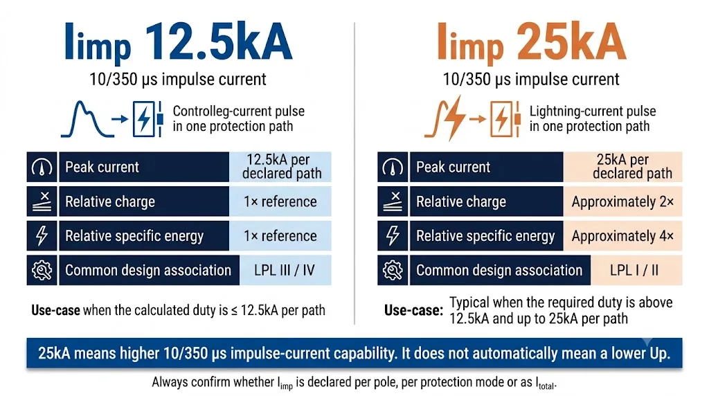
Sélectionner Iimp 12,5kA lorsque le calcul ou la règle de projet acceptée montre que la capacité d'impulsion requise de 10/350 μs n'est pas supérieure à 12,5kA à travers le pôle, la branche ou le mode de protection déclarés. Cela est généralement associé aux installations LPL III et IV.
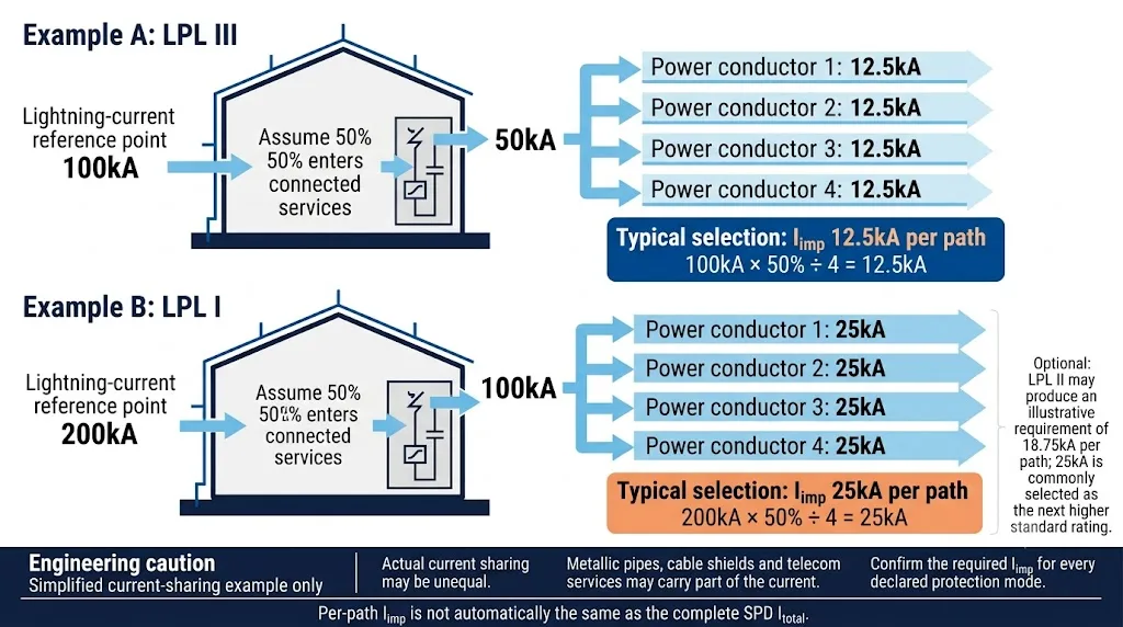
Sélectionner Iimp 25 kA lorsque le devoir requis est supérieur à 12,5kA et n'excède pas 25kA. LPL I produit couramment une exigence de 25kA dans un calcul simplifié à quatre chemins. LPL II produit une valeur illustratrice de 18,75kA, donc la prochaine valeur de produit commune supérieure est normalement 25kA.
Ne sélectionnez pas le plus grand nombre sur la fiche technique. Confirmez si Iimp s'applique à un pôle, un mode de protection ou l'ensemble de l'arrangement SPD, et vérifiez Itotal séparément.
Table des matières
Iimp 12,5kA ou 25kA : Décision en 30 secondes
Commun pour les installations LPL III/IV lorsque le calcul du partage de courant soutient 12,5kA ou moins à travers chaque chemin de protection déclaré.
Commun pour les projets LPL I et LPL II où le résultat illustratif de 18,75kA doit être arrondi à un produit de 25kA disponible.
Ne pas décider uniquement en fonction du type de bâtiment ou de la fréquence des orages locaux. Obtenir la classe LPS, l'agencement d'alimentation et la base de distribution du courant.
Qu'est-ce que Iimp sur un SPD de type 1 ?
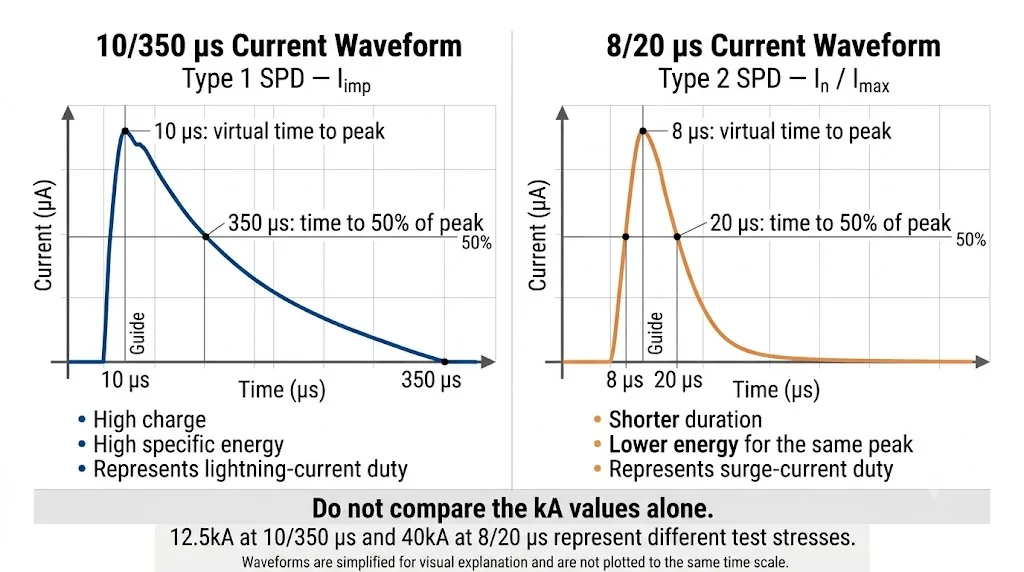
Iimp est la valeur du courant d'impulsion de crête utilisée pour exprimer la capacité de gestion du courant d'éclair d'un SPD de Type 1. Elle est exprimée en kiloampères et associée à Forme d'onde 10/350 μs.
La norme IEC 61643-11:2025 définit les exigences en courant et les méthodes d'essai pour les SPD connectés à des systèmes basse tension AC. La norme IEC 61643-12:2020 fournit des principes de sélection, d'opération, de localisation et de coordination. [1] [2]
Iimp ne doit pas être confondu avec. En ou Imax. Ces valeurs utilisent normalement la forme d'onde plus courte de 8/20 μs associée à la fonction de Type 2.
Que signifie la forme d'onde 10/350 μs ?
La notation décrit une impulsion de courant standardisée. L'onde monte rapidement vers son pic, puis décroit sur une période beaucoup plus longue que l'onde 8/20 μs utilisée pour les tests de type 2.
Qu'est-ce qui change lorsque Iimp passe de 12.5kA à 25kA?
Lorsque la forme d'onde standardisée reste la même, augmenter le courant de pointe de 12.5kA à 25kA double le courant de pointe et double approximativement la charge. Comme l'énergie spécifique est liée à l'intégrale du courant au carré, le devoir d'énergie spécifique augmente d'environ quatre fois.
Iimp 12,5kA vs 25kA : Principales différences
| Point de comparaison | Iimp 12,5kA | Iimp 25 kA | Ce que l'acheteur doit confirmer |
|---|---|---|---|
| Forme d'onde de test | 10\/350 μs | 10\/350 μs | Les deux valeurs doivent être déclarées en utilisant la même forme d'onde. |
| Courant de pointe | 12.5kA à travers le chemin ou mode déclaré | 25kA à travers le chemin ou mode déclaré | Vérifiez exactement où la valeur déclarée s'applique. |
| Association LPL typique | LPL III et IV | LPL I ; également couramment sélectionné pour LPL II | LPL II a une valeur calculée illustrative de 18,75 kA, qui est normalement arrondie à 25 kA. |
| Devoir d'énergie d'impulsion | Plus bas | Environ quatre fois le devoir d'énergie spécifique pour la même forme d'onde | La technologie produit, la taille et les performances de courant de suivi peuvent différer. |
| Niveau de protection contre les surtensions | Spécifique au produit | Spécifique au produit | Un Iimp plus élevé ne garantit pas un Up plus bas. |
| Base de sélection typique | Devoir requis ne dépassant pas 12,5 kA | Devoir requis supérieur à 12,5 kA et ne dépassant pas 25 kA | Utilisez la prochaine catégorie certifiée égale ou supérieure à la exigence calculée. |
| Impact commercial | Souvent plus compact et économique | Souvent plus grand ou basé sur un design à énergie plus élevée | Vérifiez la largeur DIN, la taille des bornes, la protection de secours et l'espace du panneau. |
Faites glisser horizontalement pour voir le tableau complet.
Comment le niveau de protection contre la foudre affecte Iimp
La norme IEC 62305 définit les niveaux de protection contre la foudre et fournit la base pour la gestion des risques liés à la foudre et les mesures de protection contre les surtensions. L'édition 2024 accorde également une plus grande attention à la dimensionnement des courants de surtension et aux considérations de partage du courant. [6] [7]
| Niveau de protection contre la foudre | Courant de référence de foudre | Calcul illustratif à quatre chemins | Sélection pratique courante |
|---|---|---|---|
| LPL I | 200kA | 200kA × 50% ÷ 4 = 25kA par chemin | Iimp 25 kA |
| LPL II | 150kA | 150 kA × 50 % ÷ 4 = 18,75 kA par voie | Iimp 25 kA comme la note commune immédiatement supérieure |
| LPL III | 100kA | 100 kA × 50 % ÷ 4 = 12,5 kA par voie | Iimp 12,5kA |
| LPL IV | Valeur de classe de référence de 100 kA | Généralement évalué sur la base d'une intensité similaire de 12,5 kA par voie | Iimp 12,5kA |
Faites glisser horizontalement pour voir le tableau complet.
Comment choisir Iimp dans des projets réels
Un courant de 12,5 kA peut convenir lorsque
- La conception repose sur la norme LPL III ou IV.
- Le courant admissible ne doit pas dépasser 12,5 kA sur chaque voie de protection déclarée.
- Les modalités de service et de cautionnement correspondent au calcul.
- La topologie SPD exacte est certifiée pour le système réseau.
Un courant de 25 kA peut s'avérer nécessaire lorsque
- La structure est conçue selon les normes LPL I ou II.
- Le besoin calculé dépasse 12,5 kA.
- Il y a moins de voies efficaces de partage du courant disponibles.
- Le cahier des charges, l'appel d'offres ou la réglementation nationale impose explicitement une intensité de 25 kA.
Est-ce que chaque bâtiment équipé d'un LPS externe a besoin d'une capacité de 25 kA ?
Non. Un système externe de protection contre la foudre implique qu'une protection de type 1 doit normalement être envisagée à la source, mais cela ne détermine pas automatiquement la valeur nominale Iimp. Un projet de niveau LPL III ou IV peut utiliser une valeur de 12,5 kA lorsque le calcul le justifie. Les niveaux LPL I ou II conduisent généralement au choix d’un produit de 25 kA. [4] [5]
Qu'en est-il des sites fortement exposés à la foudre et des sites industriels ?
Une forte activité orageuse augmente la probabilité d’un événement, mais elle ne détermine pas à elle seule une valeur fixe de l’Iimp. Les points d'entrée industriels, les hôpitaux, les installations de télécommunications, les sites à risque et autres installations critiques justifient souvent une capacité nominale plus élevée en raison du niveau de protection minimal requis (LPL), du résultat de la répartition du courant ou des conséquences d'une défaillance — et non simplement parce qu'ils sont « industriels ».
Ne pas confondre Iimp par chemin avec Itotal
Les fiches techniques relatives aux SPD de type 1 indiquent souvent plusieurs valeurs élevées en kA dans le même tableau. Celles-ci peuvent correspondre à différents modes de protection et ne doivent pas être considérées comme interchangeables.
Iimp pour un chemin ou un mode
Il s'agit du courant de impulsion circulant dans un circuit de protection déclaré, tel que L–N, L–PE, N–PE ou L–PEN.
Le fait qu'un produit soit décrit comme « 12,5 kA par pôle » ne signifie pas automatiquement que chaque mode de protection présente la même valeur.
Montant total de l'accord
Itotal correspond à une déclaration distincte pour l'ensemble du dispositif SPD multipolaire ou de l'installation testée.
Elle doit être tirée des données vérifiées par le fabricant — et non calculée en multipliant le nombre de modules.
Pourquoi les produits « 3+1 » méritent-ils une attention particulière ?
Dans un SPD de type 3+1, les voies de protection L–N et la voie N–PE peuvent présenter des valeurs Iimp différentes. Les données du fabricant peuvent indiquer séparément l’Iimp pour L–N, l’Iimp pour N–PE et l’Itotal pour l’ensemble de la configuration. [8]
Processus de sélection pratique de l'Iimp pour les SPD de type 1
Identifier le LPS externe, l'exposition directe au courant de foudre, l'alimentation aérienne, le cahier des charges ou la réglementation locale.
Ne demandez pas au fournisseur de SPD de déduire la LPL à partir du nom du bâtiment ou du secteur d'activité uniquement.
Prendre en compte les conducteurs d'alimentation entrants, les raccordements à la terre, les blindages de câbles, le dispositif de mise à la terre et une éventuelle répartition inégale.
Vérifiez si le système utilise une protection de type 1+1, 3+1, 4+0, L–N, L–PE, N–PE ou L–PEN.
Utilisez 12,5 kA lorsque le besoin ne dépasse pas 12,5 kA. Utilisez 25 kA lorsque le besoin est supérieur à 12,5 kA mais ne dépasse pas 25 kA.
Vérifier le comportement des paramètres Uc, Up, In, Imax et TOV, la résistance aux courts-circuits, le courant de suivi, la protection de secours et les exigences relatives aux conducteurs.
Vérifiez que la tension exacte, la topologie, le nombre de pôles et le code du modèle figurent bien dans le certificat ou dans le champ d'application du rapport d'essai validé.
Liste de contrôle pour l'achat en gros de SPD de type 1+2
Pour les projets de panneaux, les stocks des distributeurs et les commandes OEM, le bon de commande doit préciser davantage que la simple mention « Type 1+2, 25 kA ».
- Classification de type 1 ou de type 1+2
- Édition applicable de la norme CEI ou EN
- Valeur Iimp à 10/350 μs
- Chemin ou mode de protection couvert par Iimp
- Itotal déclaré pour l'ensemble du SPD
- Tension du système et Uc/MCOV
- Niveau de protection contre les surtensions
- In et Imax à 8/20 μs
- Système TN-C, TN-S, TN-C-S, TT ou IT
- 1+1, 3+1, 4+0 ou autre topologie
- Classifications L–N, L–PE, N–PE et L–PEN
- Capacité d'extinction par suivi du courant
- Intensité de court-circuit nominale ou résistance au court-circuit
- Protection de secours maximale autorisée
- Comportement du TOV et mode de défaillance sans risque
- Dimensions des cosses et couple de serrage
- Conception modulaire ou monobloc
- Indicateur visuel et contact d'alarme à distance
- Couverture exacte des modèles dans la certification
- Marque OEM, emballage, quantité minimale de commande et délai de livraison
Paramètres nécessitant une confirmation distincte
Iimp ne remplace pas Sélection UC, Sélection vers le haut, Cote In ou Sélection Imax. Chaque paramètre répond à une question technique différente.
| Paramètres | Ce que le fournisseur doit indiquer | Panneau d'avertissement |
|---|---|---|
| Iimp | Valeur, forme d'onde de 10/350 μs et mode de protection exact | Uniquement « SPD 25 kA » sans indication de forme d'onde ni de mode |
| Total | Valeur vérifiée pour la configuration complète | Total obtenu par multiplication informelle |
| Déclaration de type | Type 1 ou Type 1+2 selon la norme applicable | « T1+T2 » utilisé uniquement à des fins marketing |
| Certificat | Titulaire du certificat, famille de modèles exacte et portée des paramètres | Le certificat correspond à un autre modèle ou à un autre fabricant |
| Système de réseau | Topologie homologuée pour une utilisation en TN, TT ou IT | La même configuration est proposée pour tous les systèmes |
| Protection de secours | Intensité maximale admissible des fusibles ou disjoncteurs et conditions de coordination | Aucune exigence déclarée en matière de protection par sauvegarde |
| Haut de la page | Déclarés pour les modes concernés | Un Iimp plus élevé est présenté comme la preuve d'un Up plus faible |
| Homologation OEM | Modèle homologué, étiquette technique, emballage et documents | La production commence avant la validation technique |
Faites glisser horizontalement pour voir le tableau complet.
Modèle d'appel d'offres à copier et à envoyer
Veuillez transmettre les informations suivantes au fabricant de SPD afin d'éviter les demandes de précisions répétées et les devis erronés.
Questions fréquemment posées
Un parafoudre de type 1 de 25 kA est-il toujours meilleur qu'un modèle de 12,5 kA ?
Il offre une capacité de courant d'impulsion plus élevée (10/350 μs), mais cela ne signifie pas pour autant qu'il s'agisse automatiquement de la meilleure solution globale. Les paramètres Uc, Up, la topologie, les conditions de court-circuit, la protection de secours et la certification doivent également être adaptés au projet.
Un DPA de 25kA peut-il remplacer un DPA de 12,5kA ?
Il peut offrir une marge Iimp suffisante, mais uniquement si la tension nominale, le réseau, les modes de protection, la tension Up, la capacité de suivi de courant, la protection de secours, les bornes et la certification sont également adaptés.
Pourquoi le LPL II est-il généralement associé à un parafoudre de 25kA ?
Un calcul simplifié sur quatre voies donne 18,75 kA par voie. Comme 18,75 kA n’est pas une valeur nominale courante pour ce type de produit, la valeur nominale commerciale immédiatement supérieure est généralement de 25 kA.
Un système externe de protection contre la foudre doit-il toujours supporter 25 kA ?
Non. Les projets LPL III ou IV peuvent utiliser 12,5 kA lorsque cela est permis par la conception de la répartition du courant. Les projets LPL I ou II conduisent généralement à un choix de 25 kA.
Est-ce que Iimp 12.5kA est identique à Imax 12.5kA ?
Non. Iimp utilise une forme d'onde de 10/350 μs pour le cycle de service de type 1. Imax utilise une forme d'onde de 8/20 μs pour le cycle de service de type 2. Les contraintes de courant sont différentes.
Puis-je multiplier Iimp par le nombre de pôles ?
À moins que le fabricant ne déclare la valeur obtenue comme étant Itotal pour la configuration complète testée.
Que faut-il vérifier dans un SPD de type 1+2 3+1 ?
Vérifier la valeur Iimp pour les circuits L–N, la valeur Iimp pour le circuit N–PE, la valeur Itotal, Uc, Up, le comportement en cas de surintensité, la protection de secours et la compatibilité avec le système TT ou TN-S.
Que se passe-t-il si l'Iimp requis dépasse 25kA ?
Examinez une solution dédiée de type 1 offrant une capacité nominale supérieure, ainsi que l’ architecture complète de protection contre la foudre. N’utilisez pas un produit de 25 kA au-delà de ses capacités nominales et certifiées.
Besoin d'une spécification SPD de type 1+2 pour une commande OEM ?
Veuillez nous communiquer la tension du réseau, le schéma de mise à la terre, la topologie, le LPL, les valeurs requises pour Iimp et Up, les conditions de court-circuit et le marché cible. LEEYEE peut examiner les paramètres de commande avant l'établissement du devis et la validation de l'étiquette.
Références techniques
- IEC 61643-11:2025, Dispositifs de protection contre les surtensions à basse tension raccordés aux réseaux d'alimentation à courant alternatif basse tension — Exigences et méthodes d'essai . Voir la publication IEC
- IEC 61643-12:2020, Principes de sélection, de fonctionnement, d'implantation et de coordination des dispositifs de protection contre les surtensions (SPD) raccordés aux circuits d'alimentation en courant alternatif. Voir la publication IEC
- Guide d'installation électrique, choix d'un parafoudre de type 1, y compris la valeur minimale de Iimp de 12,5 kA à 10/350 μs par branche, couramment mentionnée, lorsqu'aucune règle plus stricte ne s'applique. Consulter le guide de sélection
- Phoenix Contact, gamme de dispositifs de protection contre les surtensions de type 1+2 et guides d'application pour des intensités nominales de 12,5 kA et 25 kA. Consulter la documentation technique
- Legrand, documentation technique sur les SPD modulaires, comprenant notamment des recommandations relatives à un courant de 12,5 kA par pôle pour les applications LPL III/IV. Consulter le document technique
- IEC 62305-1:2024, Protection contre la foudre — Principes généraux et paramètres des courants de foudre. Voir la publication IEC
- IEC 62305-4:2024, mesures de protection contre les surtensions pour les systèmes électriques et électroniques, y compris les aspects relatifs au partage de courant. Voir la publication IEC
- Données du fabricant DEHNshield indiquant des valeurs Iimp distinctes pour les modes L–N et N–PE, ainsi qu’une déclaration Itotal distincte. Consulter les caractéristiques techniques du produit
Les normes nationales de câblage, le cahier des charges du projet et les calculs de l'ingénieur chargé de la protection contre la foudre prévalent sur les exemples de sélection généraux. Vérifiez les dernières données techniques du produit et le champ d'application de la certification avant de passer commande.
