
La protection contre les surtensions des tours de communication doit couvrir l'ensemble du site radio, et pas seulement un SPD à l'intérieur d'un cabinet extérieur. Le même principe de niveau de site s'applique à la protection contre les surtensions des sites de cellules, à la protection contre la foudre des tours de télécommunications et à de nombreuses installations de stations de base radio.
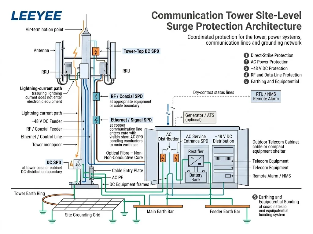
La structure de la tour, l'alimentation CA, les câbles d'alimentation DC −48 V, les interfaces d'antenne, les lignes de données en cuivre, les cabinets d'équipements et le réseau de mise à la terre du site doivent fonctionner comme un système de protection coordonné.
Table des matières
Réponse rapide
Un site de tour de communication nécessite généralement quatre fonctions coordonnées : un système de protection contre la foudre externe, un système de mise à la terre du site, un bonding équipotentiel et des SPDs correctement sélectionnés sur les lignes d'alimentation et de signal conductrices.[1][2]
L'alimentation CA, le DC −48 V, les câbles RF ou coaxiaux, Ethernet, PoE et les lignes de contrôle nécessitent des dispositifs de protection différents. Chaque SPD doit correspondre au circuit réel, à la limite d'installation et à l'exposition prévue aux surtensions.
Signification de l'acheteur : envoyer au fournisseur l'architecture du site, les tensions de fonctionnement, l'arrangement de mise à la terre, les interfaces de câbles et les positions SPD proposées. Une demande pour “ un seul SPD pour une tour de communication ” n'est pas suffisante pour une sélection fiable.
Comment la protection contre la foudre et les surtensions des tours de communication fonctionne ensemble
Une frappe directe peut envoyer un courant à travers la structure de la tour, le réseau de mise à la terre, les écrans de câbles et les services connectés. Les équipements électroniques peuvent donc être endommagés même lorsque la foudre ne frappe pas directement un port d'équipement.
L'ITU-T K.112 fournit des procédures pratiques pour la protection contre la foudre, la mise à la terre et le raccordement dans les stations de base radio autonomes et sur les toits.[2] L'ITU-T K.119 évalue quatre parties connectées du système de protection.[3]
Terminaison aérienne et chemin de courant
Le système externe intercepte la foudre directe et fournit un chemin conçu vers la terre.
Système de mise à la terre du site
La tour, l'abri et les structures associées se connectent à un réseau de mise à la terre coordonné.
Mise à la terre équipotentielle
Les structures métalliques, les écrans de câbles, les châssis d'équipement et les conducteurs de protection sont coordonnés pour limiter les différences de potentiel.
Dispositifs de protection contre les surtensions
Les SPD limitent les surtensions conduites sur les circuits AC, DC, RF, de données et de contrôle aux limites pertinentes.
Que comprend une architecture de protection complète d'un site de tour ?
Commencez par le site physique plutôt que par un catalogue de produits. Tracez les chemins de courant de foudre attendus, identifiez chaque câble conducteur traversant une limite de protection et assignez la fonction de protection correcte à cet emplacement.
- Évaluez la tour et son exposition à la foudre. Confirmer si l'installation est une tour autonome, un site en toiture, un monopole, un mât de broadcast ou une station sans fil à distance. La norme IEC 62305-2 fournit une procédure de gestion des risques pour sélectionner les mesures de protection appropriées.[5]
- Définir le système de protection contre la foudre externe. Confirmer l'arrangement des terminaisons d'air, le chemin du courant, la terminaison à la terre, les exigences de séparation et la protection contre les tensions de contact et de pas.[6]
- Établir le concept de mise à la terre du site. Identifier la charpente en acier de la tour, l'armoire, le refuge, la plaque d'entrée de câble, les barres de terre de l'alimentation, les cadres d'équipement CC, et les racks d'équipement radio.
- Cartographier chaque service conducteur. Inclure l'AC des services publics, les générateurs, le -48 V CC, les feeders coaxiaux, l'Ethernet, le PoE, le RS485, l'AISG, les lignes d'alarme, les capteurs et les circuits d'éclairage de la tour.
- Marquer chaque frontière de protection. Identifier où les câbles entrent ou sortent d'une zone équipotentielle et où l'équipement sensible est connecté.
- Sélectionner et coordonner les SPD. Use the applicable AC, DC or telecommunications SPD standard and verify the parameters required at each position.[8][9][11][12]
- Plan commissioning and maintenance. Keep indicators, remote contacts, bonding points and replaceable modules accessible for inspection.
Où les surtensions peuvent-elles entrer dans un site de tour de communication ?
The tower is the most visible exposure point, but it is not the only path. Every conductive connection between outdoor equipment, the tower, the power source, the cabinet and sensitive electronics requires review.
| Entry path | Typical exposure | Protection function | Buyer must confirm |
|---|---|---|---|
| Tower or mast | Direct strike and lightning-current flow through the structure | External LPS, current path, earth termination and bonding | Tower type, height, layout, risk assessment and LPS design |
| AC supply | Utility line, overhead section, generator, ATS or site distribution | AC SPD coordinated with the supply and lightning exposure | Voltage, phases, earthing system, Uc, Iimp or In, Up and backup protection |
| −48 V DC feeder | Long copper feeder between rectifier, DC distribution and tower-mounted radio | Low-voltage DC SPD at the required protection boundaries | Maximum bus voltage, polarity, bonding, protection modes and SPD positions |
| RF or coaxial line | Metallic antenna feeder, connector and cable shield | RF SPD and shield bonding at the designed boundary | Connector, impedance, frequency, RF power, insertion loss and VSWR |
| Ethernet or PoE | Outdoor copper network cable between different equipment areas | Data-line SPD matched to Ethernet and PoE performance | Data rate, PoE type, power, protected pairs and shielding |
| Control or alarm line | RS485, AISG, sensor, dry-contact or navigation-light circuit | Signal SPD selected for the real operating circuit | Voltage, protocol, pair count, current and terminal arrangement |
An all-dielectric optical fibre does not conduct surge current through the glass fibre. Metallic armour, strength members, hybrid power conductors, equipment housings and associated copper circuits still require assessment.
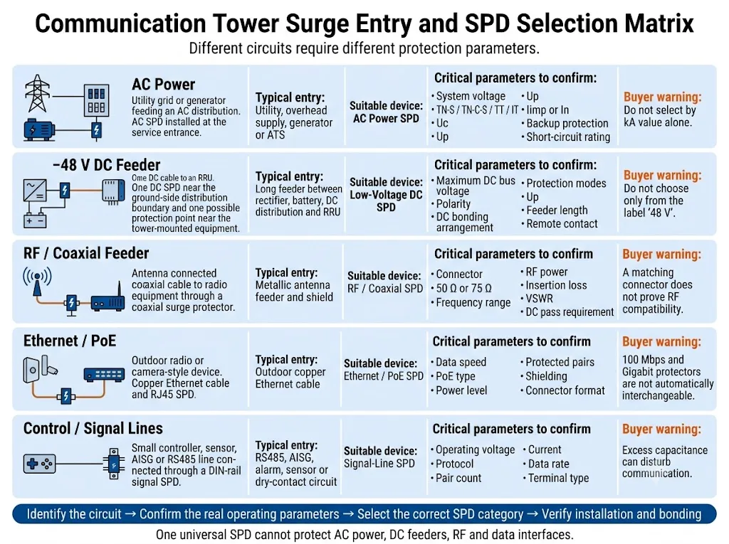
Conclusion de l'acquisition : identify the circuit before comparing discharge-current ratings. A high kA value or matching connector does not prove compatibility with the operating voltage, protection mode, frequency or data performance.
Comment la prise d'entrée CA doit-elle être protégée ?
The AC protection arrangement depends on the tower exposure, incoming supply, external lightning protection system and upstream distribution.
A stand-alone tower with an exposed incoming service can require a different solution from rooftop equipment supplied through a protected building distribution system.
IEC 61643-11:2025 specifies requirements and test methods for SPDs connected to AC low-voltage power systems.[9] IEC 61643-12:2020 addresses AC SPD selection, operation, location and coordination.[10]
Confirm these AC parameters
- System voltage and Uc: use the real maximum continuous operating voltage, not only the nominal network label.
- Système de mise à la terre : TN-S, TN-C-S, TT and IT arrangements can require different protection modes.
- Lightning-current exposure: confirm whether Type 1, Type 1+2 or another coordinated arrangement is required.
- Voltage protection level: coordinate Up with the equipment withstand level and downstream protection.
- Discharge parameters: confirm Iimp, In or Imax according to the SPD classification and project requirement.
- Short-circuit conditions: verify prospective short-circuit current, SPD short-circuit capability and backup protection.
- Alternative power paths: include generators, ATS circuits and any other connected source.
- Connection path: keep the complete SPD connection short and direct because conductor inductance adds voltage during a fast surge.
Comment le câble d'alimentation DC −48 V doit-il être protégé ?
Radio sites commonly use rectifiers and batteries to supply tower-mounted radio equipment through long copper DC feeders. A transient can enter from the tower side or appear through a potential difference between tower equipment and ground-level equipment.
IEC 61643-41:2025 applies to SPDs connected to DC power circuits and equipment rated up to 1,500 V DC.[11] The selected device must still be designed and rated for the actual low-voltage telecom circuit.
Do not select from the label “48 V” alone
The DC bus can rise above its nominal value during rectifier operation, battery charging or system adjustment. Confirm the highest continuous operating voltage before fixing the SPD voltage rating.
| DC question | Pourquoi c'est important | Information to provide |
|---|---|---|
| Maximum bus voltage | An unsuitable continuous voltage can cause premature ageing or an inappropriate protection level. | Rectifier range, battery float voltage, charging voltage and abnormal operating limits. |
| DC bonding arrangement | Protection modes depend on the relationship between DC+, return, DC− and PE. | Single-line diagram and the project bonding or earthing arrangement. |
| Feeder exposure | A long feeder crossing different equipment areas can require coordinated protection at more than one boundary. | Feeder length, route, tower height, radio locations and proposed SPD positions. |
| Status monitoring | A fault at an unmanned site can remain unnoticed without a remote signal. | Required NO, NC or changeover contact and the RTU or NMS alarm logic. |
Comment les lignes RF, Ethernet et de contrôle doivent-elles être protégées ?
Each protector must preserve the normal performance of its circuit while limiting transient voltage. A device can fit mechanically and still be electrically unsuitable.
RF and coaxial feeders
Confirm the connector type, characteristic impedance, operating frequency, RF power, insertion loss, return loss or VSWR, DC-pass requirement and environmental rating.
The cable shield and RF protector should be bonded at the position required by the site design. Protection or bonding at both ends can be appropriate in some architectures, but it is not a universal rule.
Ethernet and PoE
IEC 61643-21:2025 covers SPDs for telecommunications and signalling networks, including networks that provide power on the same line, such as PoE.[12]
Confirm the Ethernet speed, PoE type, maximum power, protected pairs, shielding and acceptable insertion performance. A device designed for 100 Mbps or lower-power PoE should not be assumed suitable for Gigabit Ethernet or higher-power PoE.
RS485, AISG, alarm and sensor circuits
Match the SPD to the operating voltage, maximum signal level, number of conductors, current, data rate, reference conductor and terminal arrangement.
Excess capacitance or an unsuitable protection level can disturb communication even when the SPD itself remains operational.
Pourquoi la mise à la terre et le bonding équipotentiel déterminent-ils le résultat ?
An SPD diverts surge current into the bonding and earthing network. If that path is long, indirect, corroded or poorly coordinated, the voltage at the protected equipment can be significantly higher than the SPD datasheet Up value.
Site bonding is not simply a collection of earth rods. Its purpose is to reduce dangerous potential differences between the tower, cabinet, shelter, cable shields, AC PE, DC equipment and other conductive systems during a lightning event.[2][7]
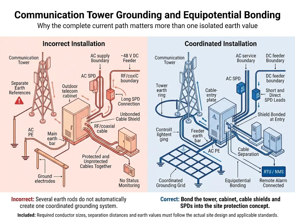
One earth-resistance value is not the complete answer
Earth resistance is important, but the result also depends on conductor routes, inductance, network geometry, soil conditions, current sharing, connection quality, corrosion and bonding position.
Do not promise that every tower is protected when the measured resistance is below one fixed value. Acceptance criteria must follow the site specification, local regulations, measurement method and qualified lightning-protection design.
Bonding points that normally require review
- Tower steelwork, monopole or mast base.
- External down-conductors where separately installed.
- Tower-base earth bar and equipment-room main bonding bar.
- Outdoor cabinet frame, door, cable-entry plate and internal PE bar.
- Coaxial cable shields and feeder earth bars.
- AC PE, generator earthing and ATS-related bonding.
- Rectifier, battery rack, DC distribution and telecommunications racks.
- Metallic cable trays, fences and auxiliary tower equipment where required by the design.
Pourquoi la frontière entre la tour et le cabinet est-elle critique ?
The point where cables leave the tower and enter an outdoor cabinet or shelter combines exposed conductors, cable shields, bonding connections and sensitive electronic ports.
- Place the correct SPD close to the relevant cable-entry or equipment boundary.
- Bond cable shields at the feeder earth bar or entry point defined by the site design.
- Use short, direct SPD bonding conductors.
- Separate protected and unprotected cable sections to reduce surge re-coupling.
- Avoid unnecessary loops, sharp routing changes and excess conductor length.
- Integrate the tower, cabinet and shelter into the coordinated site bonding system.
- Keep indicators, replaceable modules and remote terminals accessible after installation.
Comment l'alarme à distance et la maintenance doivent-elles être planifiées ?
Many communication towers are remote or unmanned. A failed module, disconnected bonding conductor or corroded connection can remain unnoticed until another surge event.
ITU-T K.119 addresses visual inspection, measurement, analysis and other methods used to assess the reliability of radio base station lightning protection and earthing systems.[3] IEC 62305-4 also covers inspection, maintenance and testing of surge protection measures.[7]
Remote monitoring can report
- Normal or failed SPD module status.
- Module removal where the SPD mechanism supports it.
- NO, NC or changeover dry-contact state.
- An alarm input to an RTU, PLC, cabinet controller or network-management system.
Remote indication supports maintenance, but it does not replace physical inspection. Corrosion, loose conductors, enclosure damage and incorrect replacement modules may not be detected by one auxiliary contact.
Inspect the protection system
- During initial commissioning and acceptance.
- At the scheduled preventive-maintenance interval.
- After a recorded lightning event or unexplained equipment fault.
- After adding antennas, radios, power equipment or another cabinet.
- After grounding work, civil work or cable-route changes.
- When an SPD indicator or remote alarm changes state.
Comment le type de site change-t-il la décision de protection ?
Stand-alone ground tower
This site normally has its own tower, earth network, utility or generator supply, equipment enclosure and several exposed copper conductors. It can require direct-strike protection plus coordinated AC, DC, RF and signal-line SPDs.
Rooftop radio installation
Rooftop equipment shares the building lightning protection system, main earthing terminal and electrical distribution. The designer must review separation distance, protection zones and coordination with existing building SPDs.
Remote microwave or monitoring site
This site may use batteries, solar power, a small AC source, long Ethernet or control lines and limited maintenance access. The selection must follow the real conductive interfaces and power architecture.
Conclusion de l'ingénierie : “communication tower” does not identify one universal SPD package. The physical site and cable architecture determine which protection functions are required.
Comment un acheteur doit-il vérifier le paquet SPD proposé ?
Diagrams explain the protection concept, but they are not product approvals. Before approving a tower-site package, verify each proposed model against the circuit it will protect.
Request model-specific evidence
LEEYEE is a specialized surge protection and low-voltage protection supplier. CNSPD is LEEYEE’s surge protection-focused platform for global technical buyers.
A certificate for one series or configuration must not be treated automatically as approval for every voltage, pole arrangement, connector or OEM variant. Confirm the exact document scope before project submission.
Que doit-on confirmer avant de commander ?
Prepare the following information before requesting model recommendations, samples, technical files or an OEM quotation.
Demander un examen de la configuration SPD de la tour de communication
Share the site single-line diagram, tower and cabinet layout, AC supply details, maximum DC bus voltage, cable interfaces and grounding drawing with LEEYEE.
Proposed models and installation positions must be confirmed against the actual equipment instructions, local electrical rules, project specification and qualified lightning-protection design.
FAQ sur la protection contre les surtensions des tours de communication
Can one AC SPD protect the complete communication tower site?
Does every communication tower require a Type 1 SPD?
Where should the −48 V DC SPD be installed?
Can a PV DC SPD be used for a 48 V telecom system?
Does optical fibre remove the need for surge protection?
Should an RF surge protector be installed at both cable ends?
Is a low grounding-resistance value enough?
Is remote alarm useful at a tower site?
Which documents should an OEM buyer request?
Références
- International Telecommunication Union, ITU-T K.56 (05/2021), Protection of radio base stations against lightning discharges. Official ITU publication.
- International Telecommunication Union, ITU-T K.112 (05/2021), Lightning protection, earthing and bonding: Practical procedures for radio base stations. Official ITU publication.
- International Telecommunication Union, ITU-T K.119 (12/2016), Conformance assessment of radio base stations regarding lightning protection and earthing. Official ITU publication.
- International Electrotechnical Commission, IEC 62305-1:2024, Protection against lightning – Part 1: General principles. Official IEC publication.
- International Electrotechnical Commission, IEC 62305-2:2024, Protection against lightning – Part 2: Risk management. Official IEC publication.
- International Electrotechnical Commission, IEC 62305-3:2024, Protection against lightning – Part 3: Physical damage to structures and life hazard. Official IEC publication.
- International Electrotechnical Commission, IEC 62305-4:2024, Protection against lightning – Part 4: Electrical and electronic systems within structures. Official IEC publication.
- International Electrotechnical Commission, IEC 61643-01:2024, Low-voltage surge protective devices – Part 01: General requirements and test methods. Official IEC publication.
- International Electrotechnical Commission, IEC 61643-11:2025, Low-voltage surge protective devices – Part 11: Surge protective devices connected to AC low-voltage power systems – Requirements and test methods. Official IEC publication.
- International Electrotechnical Commission, IEC 61643-12:2020, Low-voltage surge protective devices – Part 12: Surge protective devices connected to low-voltage power systems – Selection and application principles. Official IEC publication.
- International Electrotechnical Commission, IEC 61643-41:2025, Low-voltage surge protective devices – Part 41: Surge protective devices connected to DC low-voltage power systems – Requirements and test methods. Official IEC publication.
- International Electrotechnical Commission, IEC 61643-21:2025, Low-voltage surge protective devices – Part 21: Surge protective devices connected to telecommunications and signalling networks – Requirements and test methods. Official IEC publication.
- International Electrotechnical Commission, IEC 61643-31:2018, Low-voltage surge protective devices – Part 31: Requirements and test methods for SPDs for photovoltaic installations. Official IEC publication.
