
La protection contre les surtensions des tours de communication doit couvrir l'ensemble du site radio, et pas seulement un SPD à l'intérieur d'un cabinet extérieur. Le même principe de niveau de site s'applique à la protection contre les surtensions des sites de cellules, à la protection contre la foudre des tours de télécommunications et à de nombreuses installations de stations de base radio.
La structure de la tour, l'alimentation CA, les câbles d'alimentation DC −48 V, les interfaces d'antenne, les lignes de données en cuivre, les cabinets d'équipements et le réseau de mise à la terre du site doivent fonctionner comme un système de protection coordonné.
Table des matières
Réponse rapide
Un site de tour de communication nécessite généralement quatre fonctions coordonnées : un système de protection contre la foudre externe, un système de mise à la terre du site, un bonding équipotentiel et des SPDs correctement sélectionnés sur les lignes d'alimentation et de signal conductrices.[1][2]
L'alimentation CA, le DC −48 V, les câbles RF ou coaxiaux, Ethernet, PoE et les lignes de contrôle nécessitent des dispositifs de protection différents. Chaque SPD doit correspondre au circuit réel, à la limite d'installation et à l'exposition prévue aux surtensions.
Signification de l'acheteur : envoyer au fournisseur l'architecture du site, les tensions de fonctionnement, l'arrangement de mise à la terre, les interfaces de câbles et les positions SPD proposées. Une demande pour “ un seul SPD pour une tour de communication ” n'est pas suffisante pour une sélection fiable.
Comment la protection contre la foudre et les surtensions des tours de communication fonctionne ensemble
Une frappe directe peut envoyer un courant à travers la structure de la tour, le réseau de mise à la terre, les écrans de câbles et les services connectés. Les équipements électroniques peuvent donc être endommagés même lorsque la foudre ne frappe pas directement un port d'équipement.
L'ITU-T K.112 fournit des procédures pratiques pour la protection contre la foudre, la mise à la terre et le raccordement dans les stations de base radio autonomes et sur les toits.[2] L'ITU-T K.119 évalue quatre parties connectées du système de protection.[3]
Terminaison aérienne et chemin de courant
Le système externe intercepte la foudre directe et fournit un chemin conçu vers la terre.
Système de mise à la terre du site
La tour, l'abri et les structures associées se connectent à un réseau de mise à la terre coordonné.
Mise à la terre équipotentielle
Les structures métalliques, les écrans de câbles, les châssis d'équipement et les conducteurs de protection sont coordonnés pour limiter les différences de potentiel.
Dispositifs de protection contre les surtensions
Les SPD limitent les surtensions conduites sur les circuits AC, DC, RF, de données et de contrôle aux limites pertinentes.
Que comprend une architecture de protection complète d'un site de tour ?
Commencez par le site physique plutôt que par un catalogue de produits. Tracez les chemins de courant de foudre attendus, identifiez chaque câble conducteur traversant une limite de protection et assignez la fonction de protection correcte à cet emplacement.
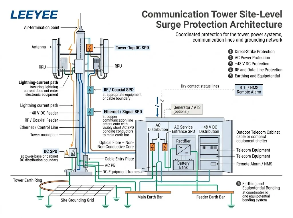
- Évaluez la tour et son exposition à la foudre. Confirmer si l'installation est une tour autonome, un site en toiture, un monopole, un mât de broadcast ou une station sans fil à distance. La norme IEC 62305-2 fournit une procédure de gestion des risques pour sélectionner les mesures de protection appropriées.[5]
- Définir le système de protection contre la foudre externe. Confirmer l'arrangement des terminaisons d'air, le chemin du courant, la terminaison à la terre, les exigences de séparation et la protection contre les tensions de contact et de pas.[6]
- Établir le concept de mise à la terre du site. Identifier la charpente en acier de la tour, l'armoire, le refuge, la plaque d'entrée de câble, les barres de terre de l'alimentation, les cadres d'équipement CC, et les racks d'équipement radio.
- Cartographier chaque service conducteur. Inclure l'AC des services publics, les générateurs, le -48 V CC, les feeders coaxiaux, l'Ethernet, le PoE, le RS485, l'AISG, les lignes d'alarme, les capteurs et les circuits d'éclairage de la tour.
- Marquer chaque frontière de protection. Identifier où les câbles entrent ou sortent d'une zone équipotentielle et où l'équipement sensible est connecté.
- Sélectionner et coordonner les SPD. Utilisez la norme parafoudre (SPD) CA, CC ou télécommunications applicable et vérifiez les paramètres requis à chaque position.[8][9][11][12]
- Planifiez la mise en service et la maintenance. Maintenez les indicateurs, les contacts distants, les points de liaison et les modules remplaçables accessibles pour inspection.
Où les surtensions peuvent-elles entrer dans un site de tour de communication ?
La tour constitue le point d'exposition le plus visible, mais ce n'est pas la seule voie. Chaque connexion conductrice entre l'équipement extérieur, la tour, la source d'alimentation, l'armoire et les composants électroniques sensibles doit être examinée.
| Chemin d’entrée | Exposition typique | Fonction de protection | L’acheteur doit confirmer |
|---|---|---|---|
| Tour ou mât | Impact direct et circulation du courant de foudre à travers la structure | Système de protection externe contre la foudre (LPS), chemin du courant, prise de terre et liaison équipotentielle | Type de pylône, hauteur, configuration, évaluation des risques et conception du système de protection contre la foudre |
| Alimentation CA | Ligne de service public, section aérienne, générateur, inverseur de source (ATS) ou distribution sur site | Parafoudre CA coordonné avec l'alimentation et l'exposition à la foudre | Tension, phases, régime de neutre, Uc, Iimp ou In, Up et protection de secours |
| Alimentation à −48 V CC | Longue ligne d'alimentation en cuivre entre le redresseur, la distribution CC et la radio montée sur pylône | Parafoudre CC basse tension aux limites de protection requises | Tension maximale du bus, polarité, liaison équipotentielle, modes de protection et positions du parafoudre |
| Ligne RF ou coaxiale | Alimentation d'antenne métallique, connecteur et blindage de câble | Protection contre les surtensions RF et liaison équipotentielle de blindage à la limite définie | Connecteur, impédance, fréquence, puissance RF, perte d'insertion et ROS |
| Ethernet ou PoE | Câble réseau en cuivre pour extérieur entre différentes zones d'équipement | Parafoudre pour ligne de données adapté aux performances Ethernet et PoE | Débit de données, type de PoE, puissance, paires protégées et blindage |
| Ligne de commande ou d'alarme | Circuit RS485, AISG, capteur, contact sec ou feu de navigation | Parafoudre sélectionné pour le circuit de fonctionnement réel | Tension, protocole, nombre de paires, courant et disposition des bornes |
Une fibre optique entièrement diélectrique ne conduit pas le courant de surtension à travers la fibre de verre. Le blindage métallique, les éléments de renforcement, les conducteurs d'alimentation hybrides, les boîtiers d'équipement et les circuits en cuivre associés nécessitent toujours une évaluation.
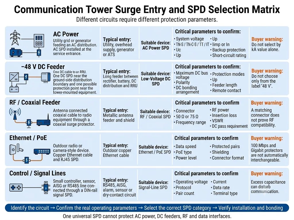
Conclusion de l'acquisition : Identifiez le circuit avant de comparer les valeurs nominales de courant de décharge. Une valeur kA élevée ou un connecteur correspondant ne garantit pas la compatibilité avec la tension de fonctionnement, le mode de protection, la fréquence ou les performances des données.
Comment la prise d'entrée CA doit-elle être protégée ?
Le dispositif de protection CA dépend de l'exposition de la tour, de l'alimentation entrante, du système de protection externe contre la foudre et de la distribution en amont.
Une tour isolée avec un service d'alimentation exposé peut nécessiter une solution différente de celle d'un équipement en toiture alimenté par un système de distribution de bâtiment protégé.
La norme IEC 61643-11:2025 spécifie les exigences et les méthodes d'essai pour les parafoudres connectés aux réseaux de distribution basse tension CA.[9] La norme IEC 61643-12:2020 traite de la sélection, du fonctionnement, de l'emplacement et de la coordination des parafoudres CA.[10]
Confirmez ces paramètres CA
- Tension du système et Uc : utilisez la tension de fonctionnement continu maximale réelle, et non uniquement l'étiquette nominale du réseau.
- Système de mise à la terre : Les configurations TN-S, TN-C-S, TT et IT peuvent nécessiter des modes de protection différents.
- Exposition aux courants de foudre : confirmez si un dispositif de Type 1, Type 1+2 ou une autre configuration coordonnée est requis.
- Niveau de protection en tension : Coordonnez la montée en puissance avec le niveau de tenue de l'équipement et la protection en aval.
- Paramètres de décharge : Confirmez Iimp, In ou Imax conformément à la classification du parafoudre et aux exigences du projet.
- Conditions de court-circuit : Vérifiez le courant de court-circuit présumé, la capacité de court-circuit du parafoudre et la protection de secours.
- Chemins d'alimentation alternatifs : incluent les générateurs, les circuits ATS et toute autre source connectée.
- Chemin de connexion : maintenez la connexion complète du parafoudre courte et directe, car l'inductance du conducteur augmente la tension lors d'une surtension rapide.
Comment le câble d'alimentation DC −48 V doit-il être protégé ?
Les sites radio utilisent couramment des redresseurs et des batteries pour alimenter les équipements radio montés sur pylône via de longues lignes d'alimentation CC en cuivre. Une transitoire peut provenir du côté du pylône ou apparaître en raison d'une différence de potentiel entre l'équipement du pylône et celui au niveau du sol.
La norme IEC 61643-41:2025 s'applique aux parafoudres connectés aux circuits d'alimentation CC et aux équipements d'une tension nominale allant jusqu'à 1 500 V CC.[11] Le dispositif sélectionné doit impérativement être conçu et dimensionné pour le circuit de télécommunication basse tension réel.
Ne pas se baser uniquement sur l'étiquette « 48 V »
Le bus CC peut dépasser sa valeur nominale lors du fonctionnement du redresseur, de la charge de la batterie ou du réglage du système. Confirmez la tension de fonctionnement continue maximale avant de fixer la tension nominale du parafoudre.
| Question sur le courant continu | Pourquoi c'est important | Informations à fournir |
|---|---|---|
| Tension maximale du bus | Une tension continue inadaptée peut entraîner un vieillissement prématuré ou un niveau de protection inapproprié. | Gamme de redresseurs, tension de maintien de la batterie, tension de charge et limites de fonctionnement anormales. |
| Dispositif de liaison CC | Les modes de protection dépendent de la relation entre DC+, le retour, DC− et PE. | Schéma unifilaire et dispositif de liaison équipotentielle ou de mise à la terre du projet. |
| Exposition de l'alimentation | Une longue ligne d'alimentation traversant différentes zones d'équipement peut nécessiter une protection coordonnée à plus d'une limite. | Longueur du feeder, tracé, hauteur de la tour, emplacements radio et positions proposées des parafoudres (SPD). |
| Surveillance de l'état | Une défaillance sur un site non supervisé peut passer inaperçue en l'absence de signal à distance. | Contact NO, NF ou inverseur requis ainsi que la logique d'alarme de l'unité de télémétrie (RTU) ou du système de gestion réseau (NMS). |
Comment les lignes RF, Ethernet et de contrôle doivent-elles être protégées ?
Chaque protecteur doit préserver le fonctionnement normal de son circuit tout en limitant les tensions transitoires. Un dispositif peut être mécaniquement compatible tout en étant électriquement inadapté.
Alimentateurs RF et coaxiaux
Veuillez confirmer le type de connecteur, l'impédance caractéristique, la fréquence de fonctionnement, la puissance RF, la perte d'insertion, la perte de retour ou le ROS, les exigences de passage CC et la classification environnementale.
Le blindage du câble et le protecteur RF doivent être reliés à la terre à l'emplacement requis par la conception du site. Une protection ou une liaison aux deux extrémités peut être appropriée dans certaines architectures, mais ce n'est pas une règle universelle.
Ethernet et PoE
La norme IEC 61643-21:2025 couvre les parafoudres destinés aux réseaux de télécommunications et de signalisation, y compris ceux assurant l'alimentation sur la même ligne, comme le PoE.[12]
Vérifiez la vitesse Ethernet, le type de PoE, la puissance maximale, les paires protégées, le blindage et les performances d'insertion acceptables. Un appareil conçu pour 100 Mbps ou un PoE de faible puissance ne doit pas être considéré comme adapté au Gigabit Ethernet ou à un PoE de plus forte puissance.
Circuits RS485, AISG, d'alarme et de capteurs
Adaptez le parafoudre à la tension de fonctionnement, au niveau de signal maximal, au nombre de conducteurs, au courant, au débit de données, au conducteur de référence et à la disposition des bornes.
Une capacité excessive ou un niveau de protection inadapté peut perturber la communication, même lorsque le parafoudre lui-même reste opérationnel.
Pourquoi la mise à la terre et le bonding équipotentiel déterminent-ils le résultat ?
Un parafoudre dévie le courant de surtension vers le réseau de liaison équipotentielle et de mise à la terre. Si ce chemin est long, indirect, corrodé ou mal coordonné, la tension au niveau de l'équipement protégé peut être nettement supérieure à la valeur Up indiquée sur la fiche technique du parafoudre.
La liaison équipotentielle du site ne se résume pas à un simple ensemble de piquets de terre. Son objectif est de réduire les différences de potentiel dangereuses entre la tour, l'armoire, l'abri, les blindages de câbles, la terre de protection CA, l'équipement CC et les autres systèmes conducteurs lors d'un événement de foudre.[2][7]
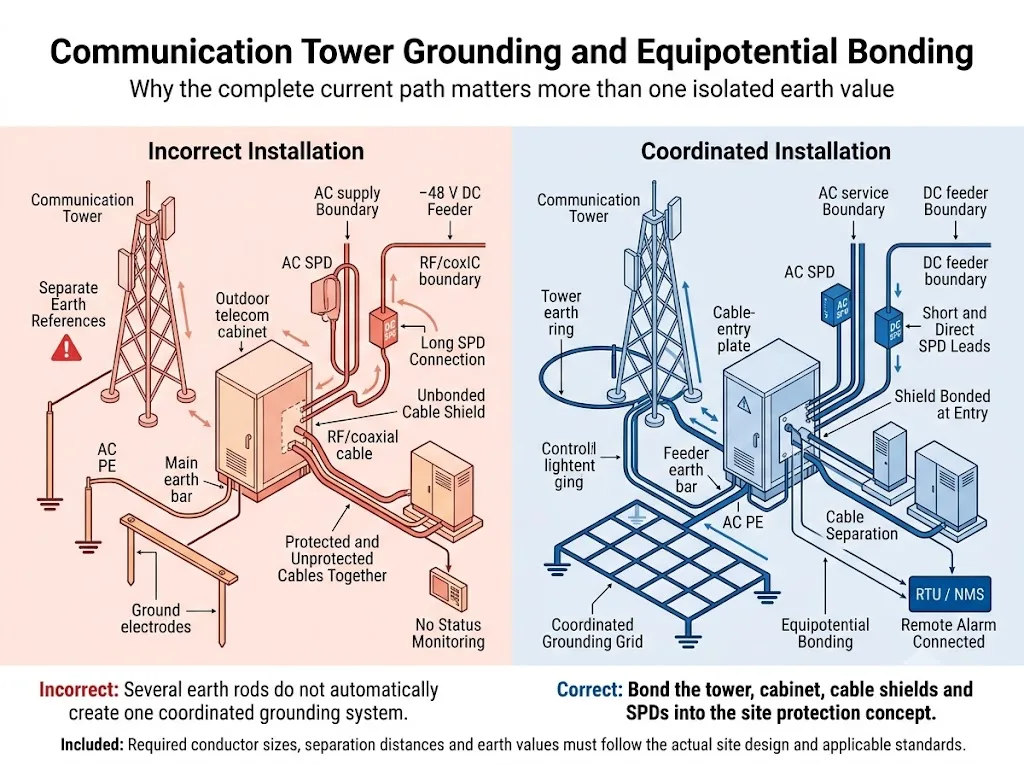
Une valeur de résistance de terre ne constitue pas une réponse complète.
La résistance de terre est importante, mais le résultat dépend également des tracés des conducteurs, de l'inductance, de la géométrie du réseau, des conditions du sol, du partage du courant, de la qualité des connexions, de la corrosion et de la position de la liaison.
Ne garantissez pas la protection de chaque pylône lorsque la résistance mesurée est inférieure à une valeur fixe. Les critères d'acceptation doivent être conformes aux spécifications du site, aux réglementations locales, à la méthode de mesure et à une conception qualifiée de protection contre la foudre.
Points d'équipotentialité nécessitant généralement un examen
- Charpente métallique du pylône, base de mât ou de monopôle.
- Conducteurs de descente externes lorsqu'ils sont installés séparément.
- Barre de terre de base de pylône et barre d'équipotentialité principale du local technique.
- Châssis d'armoire extérieure, porte, plaque d'entrée de câbles et barre de protection électrique interne.
- Blindages de câbles coaxiaux et barres de terre des feeders.
- CA PE, mise à la terre du générateur et liaison liée à l'ATS.
- Redresseur, baie de batterie, distribution CC et baies de télécommunications.
- Chemins de câbles métalliques, clôtures et équipements auxiliaires de pylône lorsque la conception l'exige.
Pourquoi la frontière entre la tour et le cabinet est-elle critique ?
Le point où les câbles quittent le pylône pour entrer dans une armoire ou un abri extérieur combine des conducteurs exposés, des blindages de câbles, des connexions de liaison et des ports électroniques sensibles.
- Placez le parafoudre approprié à proximité de l'entrée de câble ou de la limite d'équipement concernée.
- Reliez les blindages de câbles à la barre de terre d'alimentation ou au point d'entrée défini par la conception du site.
- Utilisez des conducteurs de liaison de parafoudre courts et directs.
- Séparez les sections de câbles protégées et non protégées afin de réduire le recouplage des surtensions.
- Évitez les boucles inutiles, les changements de routage brusques et les longueurs de conducteur excessives.
- Intégrez la tour, l'armoire et l'abri au système de liaison équipotentielle coordonné du site.
- Assurez-vous que les indicateurs, les modules remplaçables et les terminaux distants restent accessibles après l'installation.
Comment l'alarme à distance et la maintenance doivent-elles être planifiées ?
De nombreuses tours de communication sont isolées ou sans personnel. Un module défaillant, un conducteur de liaison déconnecté ou une connexion corrodée peuvent passer inaperçus jusqu'à la prochaine surtension.
La recommandation UIT-T K.119 traite de l'inspection visuelle, de la mesure, de l'analyse et d'autres méthodes utilisées pour évaluer la fiabilité des systèmes de protection contre la foudre et de mise à la terre des stations de base radio.[3] La norme CEI 62305-4 couvre également l'inspection, la maintenance et les essais des mesures de protection contre les surtensions.[7]
La surveillance à distance permet de générer des rapports
- État normal ou défaillant du module parafoudre.
- Retrait du module lorsque le mécanisme du parafoudre le permet.
- État de contact sec normalement ouvert (NO), normalement fermé (NF) ou inverseur.
- Une entrée d'alarme vers une unité terminale distante (RTU), un automate programmable (PLC), un contrôleur d'armoire ou un système de gestion de réseau.
La signalisation à distance facilite la maintenance, mais ne remplace pas une inspection physique. La corrosion, les conducteurs desserrés, les dommages au boîtier et les modules de remplacement incorrects peuvent ne pas être détectés par un contact auxiliaire.
Inspecter le système de protection
- Lors de la mise en service initiale et de la réception.
- À l'intervalle de maintenance préventive prévu.
- Après un événement de foudre enregistré ou une défaillance inexpliquée de l'équipement.
- Après l'ajout d'antennes, de radios, d'équipements électriques ou d'une autre armoire.
- Après des travaux de mise à la terre, des travaux de génie civil ou des modifications de cheminement de câbles.
- Lorsqu'un indicateur de parafoudre ou une alarme à distance change d'état.
Comment le type de site change-t-il la décision de protection ?
Tour au sol autonome
Ce site dispose généralement de sa propre tour, d'un réseau de mise à la terre, d'une alimentation secteur ou par générateur, d'une armoire d'équipement et de plusieurs conducteurs en cuivre exposés. Il peut nécessiter une protection contre les coups de foudre directs ainsi que des parafoudres coordonnés pour les lignes CA, CC, RF et de signal.
Installation radio en toiture
L'équipement en toiture partage le système de protection contre la foudre du bâtiment, la borne de terre principale et la distribution électrique. Le concepteur doit examiner la distance de séparation, les zones de protection et la coordination avec les parafoudres existants du bâtiment.
Site distant de micro-ondes ou de surveillance
Ce site peut utiliser des batteries, l'énergie solaire, une petite source CA, de longues lignes Ethernet ou de contrôle, et bénéficier d'un accès limité pour la maintenance. La sélection doit tenir compte des interfaces conductrices réelles et de l'architecture électrique.
Conclusion de l'ingénierie : Le terme « tour de communication » ne désigne pas un ensemble universel de parafoudres (SPD). L'emplacement physique et l'architecture des câbles déterminent les fonctions de protection requises.
Comment un acheteur doit-il vérifier le paquet SPD proposé ?
Les schémas illustrent le concept de protection, mais ne constituent pas des homologations de produits. Avant d'approuver un ensemble pour site de tour, vérifiez chaque modèle proposé par rapport au circuit qu'il doit protéger.
Demander des preuves spécifiques au modèle
LEEYEE est un fournisseur spécialisé dans la protection contre les surtensions et la protection basse tension. CNSPD est la plateforme de LEEYEE dédiée à la protection contre les surtensions pour les acheteurs techniques internationaux.
Un certificat pour une série ou une configuration donnée ne doit pas être automatiquement considéré comme une approbation pour chaque tension, disposition de pôles, connecteur ou variante OEM. Confirmez la portée exacte du document avant de soumettre votre projet.
Que doit-on confirmer avant de commander ?
Préparez les informations suivantes avant de demander des recommandations de modèles, des échantillons, des dossiers techniques ou un devis OEM.
Demander un examen de la configuration SPD de la tour de communication
Veuillez transmettre à LEEYEE le schéma unifilaire du site, la disposition de la tour et des armoires, les détails de l'alimentation CA, la tension maximale du bus CC, les interfaces de câblage ainsi que le plan de mise à la terre.
Les modèles proposés et les positions d'installation doivent être validés en fonction des instructions réelles de l'équipement, des réglementations électriques locales, du cahier des charges du projet et d'une conception qualifiée de protection contre la foudre.
FAQ sur la protection contre les surtensions des tours de communication
Un seul parafoudre CA peut-il protéger l'ensemble du site de la tour de communication ?
Chaque tour de communication nécessite-t-elle un parafoudre de type 1 ?
Où faut-il installer le SPD de −48 V CC ?
Un parafoudre CC pour installation photovoltaïque peut-il être utilisé pour un système de télécommunication 48 V ?
La fibre optique élimine-t-elle le besoin de protection contre les surtensions ?
Un parafoudre RF doit-il être installé aux deux extrémités du câble ?
Une faible valeur de résistance de mise à la terre est-elle suffisante ?
Une alarme à distance est-elle utile sur un site de pylône ?
Quels documents un acheteur OEM doit-il demander ?
Références
- Union internationale des télécommunications, UIT-T K.56 (05/2021), Protection des stations de base radioélectriques contre les décharges de foudre. Publication officielle de l'UIT.
- Union internationale des télécommunications, UIT-T K.112 (05/2021), Protection contre la foudre, mise à la terre et liaison équipotentielle : Procédures pratiques pour les stations de base radioélectriques. Publication officielle de l'UIT.
- Union internationale des télécommunications, UIT-T K.119 (12/2016), Évaluation de la conformité des stations de base radio en matière de protection contre la foudre et de mise à la terre. Publication officielle de l'UIT.
- Commission électrotechnique internationale, CEI 62305-1:2024, Protection contre la foudre – Partie 1 : Principes généraux. Publication officielle de la CEI.
- Commission électrotechnique internationale, CEI 62305-2:2024, Protection contre la foudre – Partie 2 : Évaluation du risque. Publication officielle de la CEI.
- Commission électrotechnique internationale, CEI 62305-3:2024, Protection contre la foudre – Partie 3 : Dommages physiques sur les structures et risques pour la vie humaine. Publication officielle de la CEI.
- Commission Électrotechnique Internationale, IEC 62305-4:2024, Protection contre la foudre – Partie 4 : Systèmes électriques et électroniques dans les structures. Publication officielle de la CEI.
- Commission Électrotechnique Internationale, IEC 61643-01:2024, Parafoudres basse tension – Partie 01 : Exigences générales et méthodes d'essai. Publication officielle de la CEI.
- Commission électrotechnique internationale, IEC 61643-11:2025, Parafoudres basse tension – Partie 11 : Parafoudres connectés aux réseaux basse tension – Exigences et méthodes d'essai. Publication officielle de la CEI.
- Commission électrotechnique internationale, IEC 61643-12:2020, Parafoudres basse tension – Partie 12 : Parafoudres connectés aux réseaux de distribution basse tension – Principes de choix et d'application. Publication officielle de la CEI.
- Commission électrotechnique internationale, CEI 61643-41:2025, Parafoudres basse tension – Partie 41 : Parafoudres connectés aux réseaux de distribution basse tension à courant continu – Exigences et méthodes d'essai. Publication officielle de la CEI.
- Commission électrotechnique internationale, CEI 61643-21:2025, Parafoudres basse tension – Partie 21 : Parafoudres pour réseaux de télécommunications et de signalisation – Exigences et méthodes d'essai. Publication officielle de la CEI.
- Commission électrotechnique internationale, CEI 61643-31:2018, Parafoudres basse tension – Partie 31 : Exigences et méthodes d'essai pour les parafoudres destinés aux installations photovoltaïques. Publication officielle de la CEI.
