
Choosing a 3P or 4P automatic transfer switch for a three-phase system is mainly a neutral and earthing decision, not a voltage-label decision. A 380 V, 400 V or 415 V system can require different pole arrangements depending on the source-neutral bonding, earthing system, ATS location, generator grounding and fault-protection design.
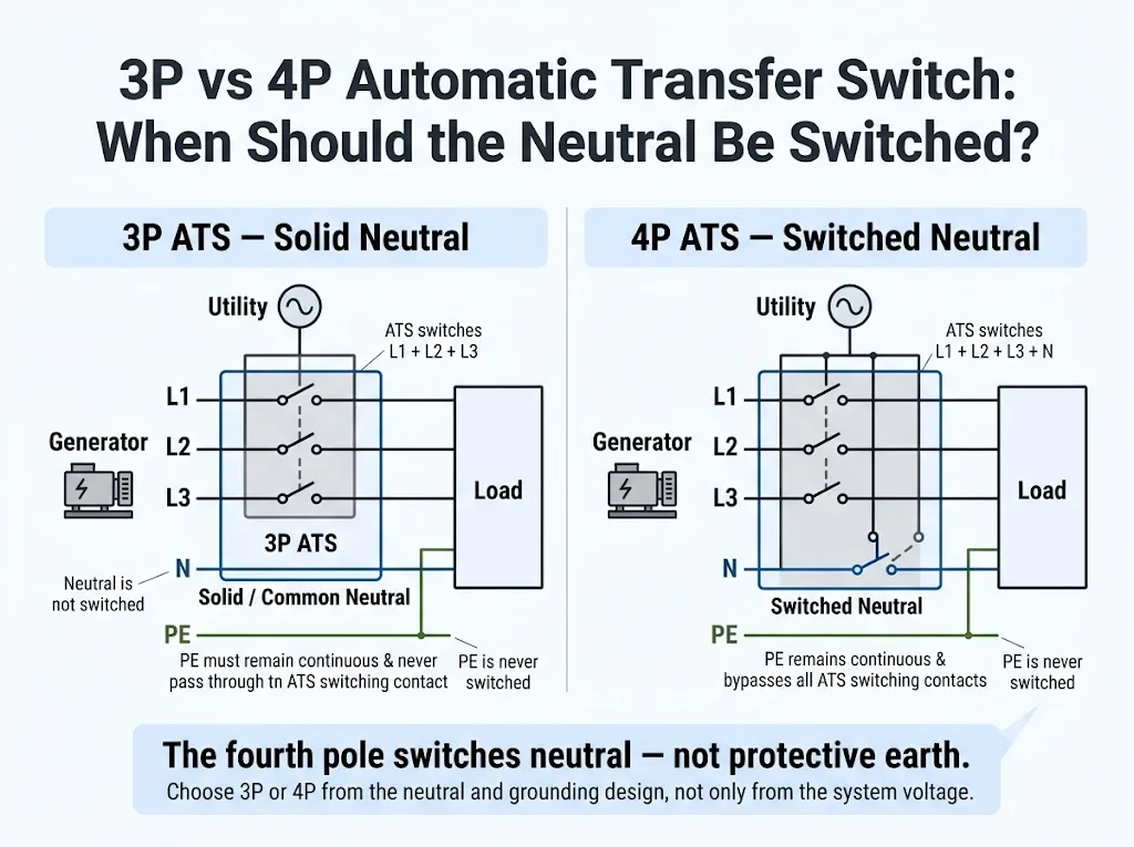
A 3P ATS switches L1, L2 and L3 while the neutral remains continuous. A 4P ATS switches L1, L2, L3 and the neutral.
Choose between them according to the source-neutral bonding and earthing design—not simply because the system is 380 V, 400 V, 415 V or three-phase. Eaton describes a fully rated fourth pole for three-phase applications where neutral switching is required, while Schneider Electric / ASCO distinguishes solid, switched and overlapping neutral arrangements.[2][3]
- Do not assume that having a neutral conductor automatically means 4P.
- Do not assume that a generator automatically means 4P.
- Do not assume that 4P is inherently safer; it is correct when the neutral must be transferred or isolated.
- For TN-C-S, locate the PEN separation point before deciding whether neutral can be switched.[6][7]
Daftar Isi
3P vs 4P ATS at a Glance
The fastest way to understand the difference is to ask one question: does the load neutral remain common between sources, or must it follow the selected source?
| Kondisi proyek | 3P ATS | ATS 4P | Apa yang harus dikonfirmasi |
|---|---|---|---|
| Three-phase load without a distributed neutral | May be sufficient | Usually no neutral-transfer benefit | ATS sensing and project wiring |
| Approved common / solid neutral between sources | Common arrangement | Bergantung pada proyek | Where the system N-E reference is established |
| Generator treated as a separately derived source | Usually not the straightforward choice | Common switched-neutral arrangement | Generator N-E bond and protection scheme |
| Sistem TT | Bergantung pada proyek | Bergantung pada proyek | RCD, source-neutral arrangement and local rules |
| Sistem TN-S | Possible with an approved common neutral | Possible where source-neutral isolation is required | Source bonding and fault protection |
| TN-C-S before PEN separation | Do not interrupt PEN | Do not use the fourth pole to interrupt PEN | ATS position and PEN split |
| TN-C-S after PEN separation | Bergantung pada proyek | Bergantung pada proyek | Neutral bonding, RCD/GFP and project rules |
Makna pembeli: never order “4P because the system is 400 V” or “3P because neutral is present.” Confirm the single-line diagram and source-neutral arrangement first.
What Does the Fourth Pole Actually Change?
The extra pole in a three-phase 4P ATS is used to transfer the neutral conductor. With a solid-neutral arrangement, the normal-source neutral, alternate-source neutral and load neutral remain interconnected. With a switched-neutral arrangement, the load neutral is connected through the transfer equipment to the selected source neutral.[3]
This matters because neutral is part of the grounding and fault-current topology. If two source neutrals have independent neutral-to-earth bonding points but remain interconnected through a solid neutral, unintended parallel return paths can affect ground-fault sensing and protection coordination. Eaton and Cummins both discuss switched-neutral arrangements in connection with separately derived sources and ground-fault protection.[2][4]
Generator Neutral Bonding Is the Key Question
Before selecting the pole configuration, identify where the generator neutral is bonded to earth and whether the generator is intended to operate as a separately derived source. Cummins guidance directly links standby-system grounding to whether the transfer equipment uses a solid neutral or a switched neutral.[4][5]
Common Neutral Arrangement
The generator neutral remains connected to the service-supplied grounded neutral. In this topology, the generator neutral is not given an additional neutral-to-earth bond that would create another fault-current return path.
A 3P ATS can be appropriate when the approved design intentionally keeps the neutral solid/common.
Separately Derived Generator
The generator establishes its own neutral-to-earth reference, and the load neutral must be transferred so that the inactive-source neutral does not remain permanently connected to the active-source neutral.
A 4P switched-neutral ATS is a common solution for this topology.
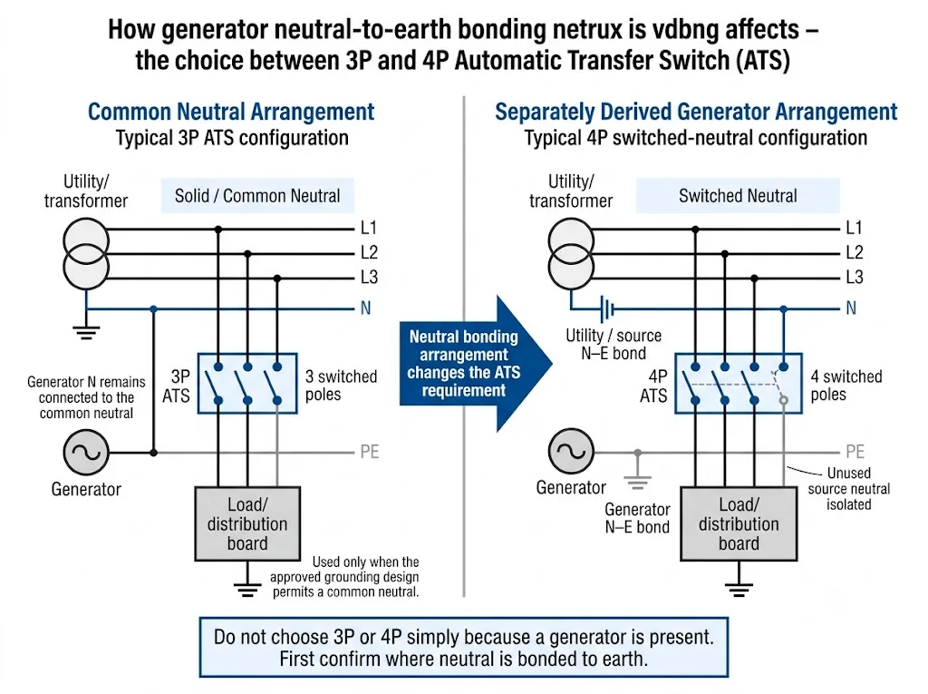
The presence of a generator does not by itself determine the pole count. What matters is whether the generator neutral is separately bonded, whether the two source neutrals may remain interconnected and how RCD or ground-fault protection is intended to operate.
How Do TT, TN-S and TN-C-S Affect the Choice?
The earthing-system label is an important starting point, but it does not provide a complete 3P-or-4P answer. The ATS designer must still confirm the source bonding arrangement, ATS location, neutral or PEN status and the applicable protection scheme.
TT System: Review Neutral Switching Together With RCD Protection
In a TT system, exposed conductive parts are connected to a local installation earth electrode, while the source neutral is earthed at the supply source. Schneider Electric's Electrical Installation Guide explains that residual-current protection plays a central role in automatic fault disconnection in TT systems because the earth-fault loop impedance can limit fault current.[8]
For an ATS project, review the neutral arrangement together with the generator neutral bonding, RCD arrangement, source isolation and applicable local wiring rules. Do not apply a universal rule such as “TT always requires 4P.”
TN-S System: Separate N and PE Do Not Automatically Decide the ATS
In TN-S, neutral and protective earth remain separate conductors throughout the TN-S portion of the installation.[6] That does not automatically mean 3P or 4P.
If an approved design allows the source neutrals to remain on one common neutral reference, a solid-neutral arrangement may be valid. If the alternate source establishes a separate grounding reference or the source neutrals must otherwise be isolated, switched neutral may be required.
The final decision must match the national wiring rules, project single-line diagram, ATS instructions and protection design.
TN-C-S System: Find the PEN Split Before Selecting the ATS
TN-C-S combines an upstream TN-C portion, where protective and neutral functions are combined in a PEN conductor, with a downstream TN-S portion where PE and N are separated.[6]
The critical rule at the ATS location is therefore straightforward: if the conductor is still PEN, do not treat it as an ordinary neutral and do not switch it as the fourth pole. Schneider Electric's Electrical Installation Guide states that the PEN conductor in TN-C performs both neutral and protective functions and must not be open-circuited.[7]
After PEN has been correctly separated into independent PE and N conductors, the neutral can be evaluated as a neutral conductor. At that point, the 3P-versus-4P decision still depends on source bonding, residual-current or ground-fault protection and the applicable project rules.
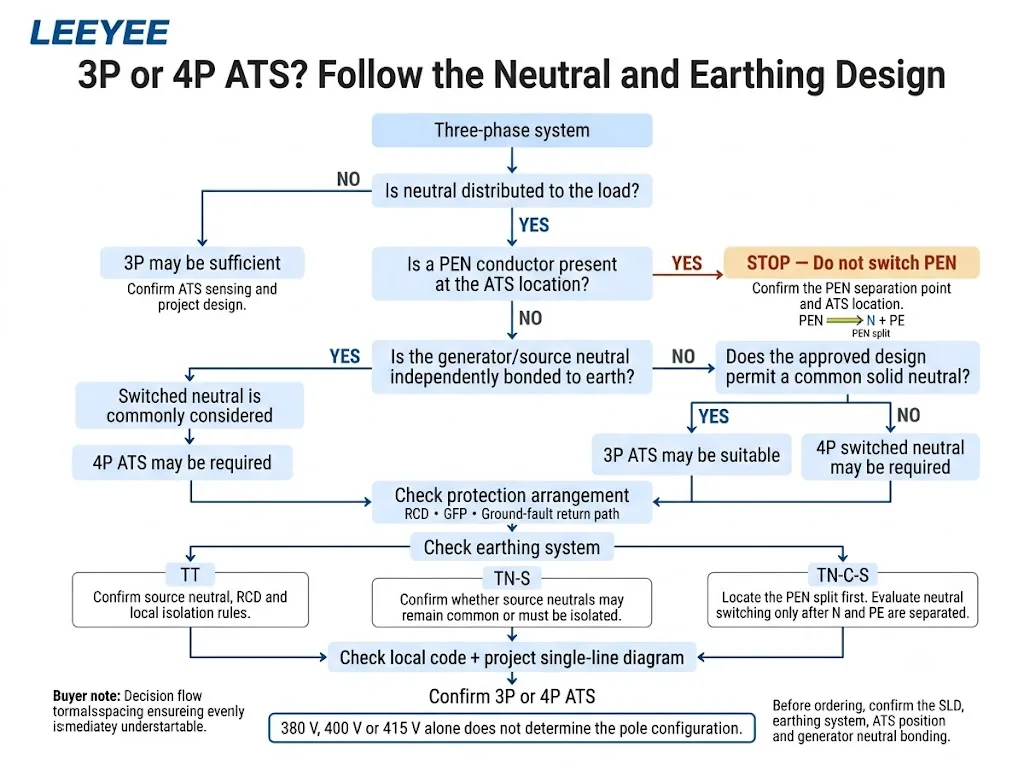
A Practical 3P vs 4P ATS Selection Sequence
- Confirm whether the load needs a neutral. A three-phase three-wire load and a three-phase four-wire load do not create the same neutral requirements.
- Identify the earthing system at the ATS location. Record TT, TN-S, TN-C-S or another arrangement, but do not stop with the label.
- Check whether PEN exists at that point. If yes, do not interrupt it as though it were an ordinary neutral conductor.[7]
- Locate every neutral-to-earth bond. Include the normal source, generator and any transformer-derived source.
- Determine whether the source neutrals may remain common. If they must be isolated, switched neutral becomes part of the design decision.
- Review RCD or GFP operation. The transfer arrangement must preserve the intended fault-current return path and sensing method.
- Check the ATS manufacturer's instructions and project requirements. Pole count must match the actual equipment and single-line diagram.
- Confirm the applicable national rules. Neutral disconnection requirements can vary by jurisdiction and installation type.
Choosing between a 3P and 4P automatic transfer switch is primarily a neutral-and-earthing decision. Nominal three-phase voltage alone does not determine whether neutral should be switched.
Solid Neutral, Switched Neutral and Overlapping Neutral
| Neutral arrangement | What happens during transfer | Typical engineering purpose |
|---|---|---|
| Solid neutral | Normal, alternate and load neutrals remain interconnected | Used where the approved system intentionally shares a common neutral reference |
| Switched neutral | An additional pole connects the load neutral to the selected source neutral | Used where source-neutral isolation is required |
| Overlapping neutral | Neutral contacts overlap briefly during transfer | Used in specific applications requiring neutral continuity; verify the exact ATS design and project requirement |
Schneider Electric / ASCO documents solid, switched and overlapping neutral configurations. Contact timing and suitability depend on the exact transfer-switch design, so confirm the manufacturer's documentation for the selected ATS.[3]
When Is a 4P ATS Commonly Considered?
A 4P switched-neutral ATS is commonly considered when the project requires the load neutral to follow the selected source. Typical engineering triggers include:
- a generator or alternate source designed as a separately derived source;
- source neutrals that must not remain permanently interconnected;
- ground-fault or residual-current protection whose correct operation depends on source-neutral isolation;
- a project specification or applicable rule requiring neutral transfer together with the active conductors.
These conditions do not mean that 4P is universally “better.” Eaton specifically links switched-neutral ATS arrangements to three-phase applications that require neutral switching and to separately derived power sources.[2]
When May a 3P ATS Be Appropriate?
A 3P ATS may be appropriate where the project intentionally uses a solid/common neutral and the protection design permits the normal and alternate source neutrals to remain connected.
It may also be sufficient where a three-phase load does not use a distributed neutral, subject to the ATS sensing, control and manufacturer requirements.
Cummins explains that when a generator neutral remains connected to the service-supplied grounded neutral through a solid-neutral transfer arrangement, the generator neutral should not also be bonded at the generator in a way that creates multiple ground-fault return paths.[4][5]
What Can Go Wrong if the Neutral Arrangement Is Incorrect?
If a solid neutral is used where the source neutrals should be isolated: unintended parallel neutral/earth current paths can affect ground-fault sensing, reduce protection sensitivity or contribute to nuisance operation.[2][4]
If a 4P ATS is installed without the correct alternate-source grounding arrangement: the fourth pole does not fix an incorrect grounding design. The active source must still have the neutral-to-earth reference required by the project and applicable rules.
If a PEN conductor is interrupted: its protective function can be lost. A PEN conductor must not be treated as an ordinary switched neutral.[7]
Three Engineering Examples
Example 1: 400 V Panel With a Common Generator Neutral
The load is three-phase four-wire, but the approved design keeps the generator neutral connected to the service neutral and does not establish an additional generator N-E bond. A 3P solid-neutral ATS may be appropriate. The final decision still requires confirmation against the protection design and applicable rules.
Example 2: Generator With Its Own Neutral-to-Earth Bond
The generator is intended to operate as a separately derived source and the inactive-source neutral must be isolated. A 4P switched-neutral ATS is commonly used for this arrangement.[2][4]
Example 3: TN-C-S Project With the ATS Before the PEN Split
The fourth conductor at the ATS is still PEN, not an ordinary neutral. Do not select a 4P ATS on the assumption that “the fourth wire should be switched.” First review the ATS location and PEN separation point. Neutral switching can be evaluated only after PE and N are correctly separated.[6][7]
Before Ordering a 3P or 4P ATS
Provide these details before fixing the pole configuration:
Do not send only “400 V, three phase, need ATS.” That information is not enough to determine neutral switching.
When sending an ATS project or OEM enquiry to LEEYEE, share the SLD, earthing system, ATS location, load wiring and generator neutral bonding arrangement so the required configuration can be reviewed against the real project conditions.
Pertanyaan yang Sering Diajukan
What is the main difference between a 3P and 4P ATS?
In the three-phase four-wire context discussed here, a 3P ATS transfers L1, L2 and L3 while neutral remains solid/common. A 4P ATS adds a fully rated neutral pole so the neutral transfers with the selected source.[2][3]
Does a 400 V three-phase system automatically need a 4P ATS?
No. System voltage alone does not determine whether neutral must be switched. Confirm the load-neutral requirement, source-neutral bonding, earthing system, protection arrangement and project rules.
Do I need a 4P ATS for a generator?
Not automatically. A 4P switched-neutral ATS is commonly used when the generator is treated as a separately derived source or when source-neutral isolation is required. A common-neutral generator arrangement may use a 3P ATS when the grounding and protection design permits it.[2][4]
Can a 3P ATS be used in a three-phase four-wire system?
Yes, in some designs. The neutral can remain solid/common while only the three phase conductors are transferred. This is correct only where the approved grounding and protection design permits both source neutrals to remain connected.
Should neutral be switched in a TN-S system?
TN-S confirms that N and PE are separate, but it does not by itself answer the ATS question. Confirm whether the source neutrals may remain common or must be isolated, then verify the protection design and applicable national rules.[6]
Does a TT system always require a 4P ATS?
No universal rule should be applied without project confirmation. TT fault protection is closely linked to the earthing and RCD arrangement, so the ATS neutral decision should be coordinated with the source-neutral design, residual-current protection and local requirements.[8]
Can an ATS switch the PEN conductor in a TN-C-S system?
A PEN conductor must not be treated as an ordinary switched neutral. If PEN is still present at the ATS location, review the ATS position and system design first. After PEN has been correctly separated into PE and N, only the neutral can then be evaluated for switching.[6][7]
Is a 4P ATS safer than a 3P ATS?
Not inherently. A 4P ATS is appropriate when the neutral must be transferred or isolated. A 3P ATS is appropriate where an approved design requires a continuous common neutral. Safety depends on matching the transfer arrangement to the grounding and protection design.
What is the difference between solid neutral and switched neutral?
With a solid neutral, the normal-source, alternate-source and load neutrals remain interconnected. With a switched neutral, an ATS neutral pole connects the load neutral only to the selected source neutral.[3]
Is every 4P ATS neutral arrangement the same?
No. Manufacturers can offer different neutral contact arrangements and timing. Schneider Electric / ASCO, for example, distinguishes switched-neutral and overlapping-neutral configurations. Always verify the exact ATS construction and manufacturer's transfer sequence for the project.[3]
This article is an engineering selection guide, not a project-specific wiring instruction. Final ATS pole count, neutral switching, grounding, bonding and protection must be confirmed against the project SLD, applicable national wiring rules, generator documentation, ATS manufacturer instructions and the responsible electrical engineer's design.
Referensi
- IEC. IEC 60947-6-1:2026, Low-voltage switchgear and controlgear – Part 6-1: Multiple function equipment – Transfer switching equipment. Publikasi resmi IEC.
- Eaton. Fundamentals of Automatic Transfer Switches (ATS). Official Eaton source.
- Schneider Electric / ASCO. Konfigurasi Netral pada Sakelar Transfer. ASCO Data Bulletin; ASCO Neutral Configuration FAQ.
- Cummins. Application Manual – Transfer Switches. Official Cummins manual.
- Cummins. Application Manual – Electrical Design, Section 5.3.5 System Grounding (Earthing). Official Cummins electrical design manual.
- Panduan Instalasi Listrik Schneider Electric. Definition of Standardised Earthing Schemes. Panduan teknis resmi.
- Panduan Instalasi Listrik Schneider Electric. Breaking of the Neutral Conductor. Panduan teknis resmi.
- Panduan Instalasi Listrik Schneider Electric. TT System – Principle. Panduan teknis resmi.
