
Panduan Teknik Distribusi Daya UPS dan SPD
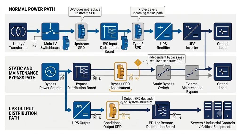
Perangkat proteksi lonjakan UPS tetap diperlukan dalam banyak sistem UPS komersial dan industri karena UPS itu sendiri tidak menggantikan proteksi lonjakan tingkat distribusi yang terkoordinasi. Input normal, bypass statis, bypass pemeliharaan, dan distribusi output harus dinilai sebagai jalur listrik yang terpisah.
Lindungi input normal UPS, evaluasi setiap sumber bypass sebagai kemungkinan jalur langsung ke beban kritis, dan pasang SPD output hanya ketika topologi UPS dan distribusi hilir menciptakan risiko lonjakan yang terdefinisi.
Daftar Isi
Apakah UPS Memerlukan Pelindung Lonjakan?
Ya, tetapi istilah “surge protector” dapat merujuk pada dua produk yang sangat berbeda. Panduan ini membahas SPD yang dipasang pada panel untuk sistem UPS komersial, industri, dan pusat data, bukan power strip colok biasa.
Strip soket kecil atau perangkat titik-pemakaian yang digunakan dekat peralatan kantor atau konsumen. Ini bukan pengganti proteksi terkoordinasi pada papan distribusi input UPS.
SPD yang dipasang paralel pada panel input, bypass, atau distribusi hilir. Pemilihannya didasarkan pada tegangan sistem, pembumian, posisi pemasangan, dan kondisi gangguan.
Mengapa UPS Tidak Dapat Menggantikan Perangkat Proteksi Lonjakan
UPS dan SPD menyelesaikan masalah kelistrikan yang berbeda. UPS menjaga kesinambungan daya. SPD membatasi tegangan lebih transien dan mengalihkan arus lonjakan sebelum merusak UPS atau beban yang terhubung.
UPS pada dasarnya bertanggung jawab untuk
- Menjaga daya selama terjadi gangguan.
- Memberikan waktu untuk start generator atau pematian terkendali.
- Mengoreksi gangguan tegangan atau frekuensi yang ditentukan.
- Menyuplai beban kritis melalui inverter atau bypass.
SPD eksternal pada dasarnya bertanggung jawab untuk
- Mengalihkan arus lonjakan sebelum mencapai komponen UPS.
- Membatasi tegangan yang muncul di terminal UPS.
- Melindungi penyearah, sakelar statis, dan sirkuit kontrol.
- Menyediakan perlindungan distribusi yang dapat diganti dan dipantau.
UPS menjaga beban tetap mendapatkan daya. SPD menjaga tegangan lebih transien dalam tingkat yang dapat diterima. Satu fungsi tidak menggantikan fungsi lainnya.
Eaton menyatakan bahwa sirkuit lonjakan UPS umumnya ditujukan untuk menangani porsi sisa dari lonjakan besar, bukan seluruh kejadian tersebut. Eaton juga merekomendasikan perlindungan untuk input UPS dan sirkuit bypass terkait, termasuk bypass pemeliharaan manual. [1] [2]
Nilai Setiap Jalur yang Dapat Mengaliri Beban Kritis
Posisi SPD harus didasarkan pada diagram garis tunggal proyek. Menempatkan satu SPD di samping kabinet UPS tidak membuktikan bahwa setiap jalur operasi dan pemeliharaan terlindungi.
Input penyearah normal
Biasanya merupakan lokasi paling jelas untuk Tipe 2 SPD yang terkoordinasi di papan distribusi input UPS.
Bypass statis atau pemeliharaan
Harus dinilai secara independen jika berasal dari papan sakelar, transformator, ATS, generator, atau pengumpan panjang lain.
Distribusi output UPS
Memerlukan penilaian kondisional untuk panel jarak jauh, kabel panjang, rute eksternal, beban sakelar, dan perilaku sumber inverter.
Pemilihan SPD pada Input UPS
Input normal biasanya merupakan posisi SPD tingkat distribusi utama. SPD harus membatasi tegangan lebih transien sebelum mencapai penyearah, pengisi daya, sakelar statis, filter, dan sirkuit kontrol elektronik.
SPD Tipe 2 umum digunakan di papan distribusi input UPS, terutama di mana perlindungan Tipe 1 atau Tipe 1+2 yang terkoordinasi sudah ada di asal bangunan. Namun, “Tipe 2, 40 kA untuk UPS” bukanlah spesifikasi yang lengkap.
| Parameter pemilihan | Apa yang harus dikonfirmasi oleh insinyur atau pembeli | Mengapa ini penting |
|---|---|---|
| Tegangan sistem | Konfirmasi tegangan fase-ke-fase dan fase-ke-netral di titik instalasi. | Tegangan pelat nama UPS saja mungkin tidak menentukan setiap mode perlindungan SPD yang diperlukan. |
| Sistem pentanahan | Konfirmasi apakah TN-S, TN-C, TT, IT, atau pengaturan proyek lainnya. | Hal ini memengaruhi Uc, jumlah kutub, dan mode perlindungan yang diperlukan. |
| Tipe SPD | Konfirmasi Tipe 1, Tipe 1+2, Tipe 2, atau kombinasi terkoordinasi. | Tipe SPD bergantung pada posisi instalasi dan paparan—bukan kVA UPS. |
| Uc | Pilih berdasarkan tegangan aktual, pengaturan pembumian, dan kemungkinan tegangan lebih sementara. | Uc yang tidak sesuai dapat menyebabkan kegagalan dini atau perlindungan yang lemah. |
| Naik | Koordinasikan tingkat perlindungan tegangan dengan persyaratan ketahanan UPS dan tegangan kabel instalasi. | Nilai Up pada katalog bukanlah tegangan total yang muncul di terminal UPS. |
| Dalam dan Imax | Tentukan arus pelepasan nominal dan maksimum berdasarkan paparan instalasi dan rencana perlindungan. | Jangan memilih peringkat kA berdasarkan ukuran UPS saja. |
| Iimp | Konfirmasi apakah posisi instalasi memerlukan kemampuan arus petir. | Iimp relevan jika tugas Tipe 1 atau arus petir parsial diperkirakan terjadi. |
| Kutub dan mode | Konfirmasi 1P+N, 2P, 3P, 3P+N, 4P, 3+1, atau 4+0 dari sistem aktual. | Konfigurasi harus sesuai dengan kondisi netral dan PE. |
| Isccr | Bandingkan peringkat hubung singkat SPD dengan arus hubung singkat prospektif di panel. | Pengaturan SPD harus tetap aman di bawah tingkat gangguan yang tersedia. |
| Perlindungan cadangan | Konfirmasi tipe dan peringkat sekring atau pemutus sirkuit yang diizinkan oleh produsen SPD. | Pemutus sirkuit pengumpan UPS tidak secara otomatis valid sebagai perlindungan cadangan SPD. |
| Pemantauan | Konfirmasi persyaratan indikasi visual, kontak kering jarak jauh, dan BMS, SCADA, atau PLC. | SPD yang gagal di ruang UPS tanpa awak tidak boleh dibiarkan tanpa pengawasan. |
Schneider Electric menyediakan contoh khusus produsen untuk sistem Galaxy UPS tertentu. Dokumentasinya menetapkan SPD Tipe 2 hulu, Up di bawah 2,5 kV, kemampuan hubung singkat yang dikoordinasikan dengan tingkat gangguan instalasi, kutub yang disesuaikan dengan sistem pembumian, dan pemantauan status operasional. [3]
Apakah Bypass UPS Memerlukan SPD Terpisah?
Sirkuit bypass dapat menghubungkan sumber AC masuk langsung ke beban kritis saat jalur penyearah dan inverter normal tidak tersedia atau sengaja diisolasi.
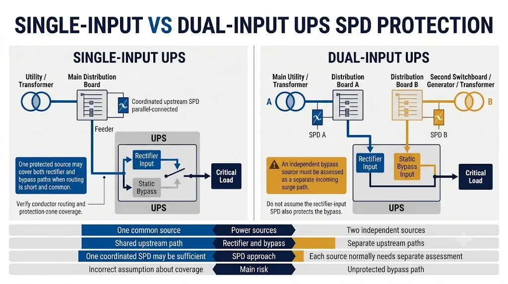
Perlakukan pasokan bypass yang independen secara elektrik sebagai jalur daya masuk terpisah sampai diagram satu garis membuktikan bahwa jalur tersebut sudah berada di dalam zona perlindungan terkoordinasi yang sama.
Satu SPD hulu yang terkoordinasi dapat melindungi keduanya jika cabang berasal dari switchboard terdekat yang sama dan perutean sambungan tetap pendek.
Sumber terpisah menciptakan kemungkinan jalur lonjakan terpisah. Hal ini memerlukan penilaian independen dan mungkin memerlukan SPD khusus.
Konfirmasi bahwa perlindungan lonjakan tetap efektif saat UPS dan panel input normal diisolasi untuk diservis.
Pengumpan panjang, bangunan terpisah, atau rute yang terpapar dapat membenarkan perlindungan di panel penerima.
Jika ya, beban tidak dapat mengandalkan jalur penyearah dan inverter selama mode operasi tersebut.
Lindungi pasokan penyearah dan pasokan bypass sesuai dengan kondisi sumber dan panel masing-masing.
Satu SPD mungkin cukup hanya jika kedua cabang tetap berada di dalam zona perlindungan efektif.
Pengaturan perlindungan harus tetap aktif saat UPS diisolasi dan diservis.
Panduan UPS Eaton merekomendasikan perlindungan lonjakan untuk sirkuit input UPS dan sirkuit bypass terkait, termasuk sirkuit bypass pemeliharaan manual. [1] [2]
Apakah SPD Diperlukan pada Output UPS?
SPD output bukan persyaratan otomatis untuk setiap UPS. Keputusannya bergantung pada sumber output UPS, pengaturan bypass, rute kabel hilir, panel penerima, beban yang terhubung, dan perilaku gangguan.
Sebelum memasang SPD langsung pada output UPS, konfirmasikan:
- Persetujuan atau persyaratan instalasi dari produsen UPS.
- Perilaku pembatasan arus dan hubung singkat output.
- Pengaturan netral dan pembumian (earthing) output.
- Kemungkinan TOV dan kondisi operasi abnormal.
- Perilaku pemutusan hubungan SPD dan perlindungan cadangan.
- Apakah perlindungan lebih baik ditempatkan di panel penerima.
| Kondisi sisi output | Arahan teknis | Alasan |
|---|---|---|
| PDU terlindungi terdekat di ruangan yang sama | SPD output tambahan mungkin tidak diperlukan. | Output tetap berada di dalam zona perlindungan terkoordinasi yang ringkas. |
| Feeder panjang ke papan distribusi jarak jauh | Nilai kebutuhan SPD pada panel penerima. | Penghantar yang panjang dapat menimbulkan paparan transien tambahan dan tegangan kabel (lead voltage). |
| Feeder memasuki gedung lain atau area eksternal | Perlindungan tambahan biasanya dapat dibenarkan. | Rute tersebut mungkin melintasi zona perlindungan petir atau titik paparan eksternal. |
| Bypass menghubungkan utilitas langsung ke bus output | Verifikasi perlindungan beban hilir selama bypass. | Jalur inverter mungkin tidak lagi memisahkan beban dari sumber masuk. |
| Motor, kontaktor, atau beban pensaklaran berbagi output yang sama | Nilai transien pensaklaran yang dihasilkan secara internal. | Tidak semua transien berasal dari sisi utilitas. |
| Sistem output IT atau sistem output yang diturunkan secara terpisah (separately derived) | Jangan memilih SPD output standar tanpa tinjauan topologi. | Uc dan mode perlindungan harus sesuai dengan pengaturan pembumian output. |
| Produsen UPS membatasi perangkat sisi output | Ikuti instruksi produsen UPS. | SPD yang tidak sesuai dapat memengaruhi perilaku pemantauan, perlindungan, atau gangguan. |
Type 1, Type 1+2, atau Type 2 untuk Sistem UPS?
Jenis SPD dipilih berdasarkan posisi pemasangan, paparan petir, dan koordinasi dengan perlindungan hulu serta hilir. Hal ini tidak ditentukan oleh kapasitas UPS saja.
Tipe 1 SPD
Digunakan di mana arus petir parsial dapat masuk ke instalasi tegangan rendah, umumnya di pintu masuk layanan atau batas zona perlindungan petir.
Tipe 1+2 SPD
Menggabungkan tugas pembatas arus petir dan pembatas tegangan. Ini dapat sesuai jika feeder UPS dimulai di dekat asal instalasi.
Tipe 2 SPD
Pilihan tingkat distribusi umum untuk input UPS, bypass, dan panel hilir ketika perlindungan Tipe 1 sudah dikoordinasikan di hulu.
Tipe 3 SPD
Tahap perlindungan halus yang terkoordinasi dan dipasang dekat dengan peralatan terminal yang sensitif. Ini tidak menggantikan perlindungan Tipe 1 atau Tipe 2 tingkat distribusi.
IEC 61643-12:2020 membahas pemilihan, pengoperasian, lokasi, dan koordinasi SPD untuk sirkuit daya tegangan rendah AC. [5]
Pembumian, Panjang Kabel, dan Proteksi Cadangan
SPD dengan peringkat yang benar masih dapat memberikan perlindungan yang buruk jika konfigurasi perkabelannya salah. Proyek UPS mungkin melibatkan netral terpisah, netral yang disaklar (switched neutral), pasokan bypass, trafo, generator, atau sistem IT.
Mode pembumian dan perlindungan
- Konfirmasikan TN-S, TN-C, TT, atau IT.
- Konfirmasikan apakah netral disaklar oleh ATS atau bypass.
- Pilih mode fasa-ke-netral, fasa-ke-PE, dan netral-ke-PE dengan benar.
- Jangan berasumsi bahwa 3P+N, 4P, 3+1, dan 4+0 dapat saling menggantikan.
- Konfirmasikan pengaturan netral input dan output secara terpisah.
Koordinasi cadangan dan hubung singkat
- Dapatkan arus hubung singkat prospektif pada posisi SPD.
- Verifikasi Isccr SPD dan perlindungan cadangan yang diizinkan.
- Gunakan sekering atau pemutus arus (breaker) yang ditentukan oleh produsen SPD.
- Periksa koordinasi dengan perlindungan hulu dan pengumpan (feeder).
- Jangan berasumsi bahwa pemutus arus pengumpan UPS secara otomatis melindungi SPD.
Jaga agar sambungan SPD tetap pendek dan langsung
Tegangan yang mencapai UPS mencakup tingkat perlindungan tegangan SPD ditambah tegangan tambahan yang timbul pada konduktor penghubung. Konduktor yang panjang, melingkar, atau diarahkan dengan buruk akan mengurangi manfaat dari nilai Up katalog yang rendah.
Pasang SPD di dekat bus yang dilindungi, gunakan konduktor langsung, dan hindari putaran yang tidak perlu. Untuk panduan pemasangan terperinci, tinjau SPD 0,5 m untuk panjang koneksi , Panduan pengardean SPD , Panduan pengkabelan SPD TN-S dan Panduan SPD sistem TT .
Alarm Jarak Jauh dan Perawatan untuk Instalasi UPS Kritis
Indikator visual mungkin cukup untuk panel kecil yang diperiksa secara berkala. Hal ini seringkali tidak cukup untuk pusat data, ruang UPS industri, lokasi telekomunikasi, atau fasilitas tanpa awak.
Fitur pemantauan yang direkomendasikan
- Indikasi status hijau dan merah lokal.
- Kontak sinyal jarak jauh bebas tegangan.
- Integrasi alarm BMS, SCADA, atau PLC.
- Logika kontak normal dan kegagalan yang jelas.
- Identifikasi SPD input, bypass, atau output mana yang telah gagal.
Fitur pemeliharaan yang direkomendasikan
- Modul perlindungan yang dapat dicolokkan dan diganti.
- Penggantian kartrid yang aman bagi jari.
- Modul cadangan tersedia selama masa pakai proyek.
- Inspeksi setelah kejadian lonjakan arus besar.
- Riwayat pemasangan dan penggantian yang tercatat.
Dokumentasi UPS Schneider terpilih mencakup indikasi status operasional di antara persyaratan SPD hulunya. [3]
Untuk integrasi kontak NO, NC, dan COM, lihat Panduan alarm jarak jauh SPD dan PLC .
Konfigurasi Proyek UPS yang Umum
Contoh-contoh ini adalah titik awal untuk tinjauan desain. Pengaturan perlindungan akhir harus mengikuti diagram satu baris proyek yang sebenarnya dan dokumentasi produsen UPS.
UPS online input tunggal
Penyearah (rectifier) dan bypass disuplai dari satu panel terlindung terdekat.
Arah tipikal: SPD Tipe 2 yang terkoordinasi dapat mencakup kedua cabang jika perutean konduktor tetap pendek dan umum.
UPS pusat data input ganda
Input penyearah dan input bypass berasal dari switchboard, sistem ATS, atau transformator yang berbeda.
Arah tipikal: Nilai setiap sumber sebagai jalur masuk independen.
UPS dengan bypass pemeliharaan eksternal
Kabinet bypass memberi energi pada beban kritis saat UPS diisolasi.
Arah tipikal: Posisikan perlindungan agar tetap efektif selama bypass pemeliharaan.
UPS yang memberi daya pada PDU jarak jauh
Pengumpan output panjang atau melintasi area eksternal atau zona perlindungan lain.
Arah tipikal: Nilai perlindungan pada panel penerima setelah mengonfirmasi kompatibilitas output UPS.
UPS industri dengan generator dan ATS
Sumber normal dan darurat dapat menyebabkan kondisi utilitas, generator, dan sakelar transfer.
Arah tipikal: Tinjau koordinasi di pintu masuk layanan, ATS, input UPS, dan sumber bypass.
Sistem UPS paralel atau redundan
Beberapa modul UPS berbagi bus input, bypass, atau output yang sama.
Arah tipikal: Konfirmasikan bahwa tidak ada konfigurasi operasi atau pemeliharaan yang menciptakan jalur yang tidak terlindungi.
Dukungan Teknik LEEYEE untuk Proyek SPD UPS
Konfirmasi model akhir harus didasarkan pada sistem kelistrikan proyek—bukan hanya nilai kA yang diminta. LEEYEE dapat meninjau kebutuhan panel input, bypass, dan hilir sebelum pesanan OEM atau jumlah besar dikonfirmasi.
Tinjauan parameter produk
Jenis Tinjauan, Uc, Up, peringkat arus pelepasan, konfigurasi kutub, persyaratan kontak jarak jauh dan modul yang dapat diganti.
Verifikasi sertifikat
Pastikan cakupan sertifikat yang tersedia dan apakah model serta tegangan yang diperlukan sudah tercakup sebelum persetujuan tender atau pesanan massal.
Dokumentasi teknis
Periksa lembar data, informasi pengabelan, dimensi, dan dokumen proyek pendukung selama persetujuan teknis.
Checklist OEM dan Pengadaan SPD UPS
Permintaan yang hanya berisi “Type 2, 40 kA untuk UPS” tidak cukup untuk pemilihan model yang andal. Pastikan informasi berikut sebelum meminta penawaran harga akhir.

- Merek, model, topologi, dan daya terukur UPS.
- Konfigurasi input tunggal atau input ganda.
- Pengaturan static bypass dan maintenance bypass.
- Diagram satu garis yang menunjukkan semua sumber daya.
- Tegangan fase-ke-fase dan fase-ke-netral.
- Frekuensi sistem dan rentang tegangan yang diizinkan.
- Sistem pembumian TN-S, TN-C, TT, IT, atau sistem pembumian proyek.
- Posisi SPD pada input, bypass, output, atau panel penerima.
- Klasifikasi Type 1, Type 1+2, atau Type 2 yang diperlukan.
- Nilai Uc, Up, In, Imax, dan Iimp yang diperlukan jika berlaku.
- Jumlah kutub dan mode perlindungan.
- Arus hubung singkat prospektif di setiap posisi.
- Sekring cadangan atau pemutus sirkuit (circuit breaker) yang diperlukan.
- Panjang sambungan dan tata letak panel.
- Indikator visual dan kontak kering jarak jauh.
- Persyaratan modul yang dapat dicolokkan (pluggable) dan kartrid cadangan.
- Sertifikasi IEC, UL, lokal, atau persyaratan tender.
- Label OEM, kemasan, kuantitas, dan jadwal pengiriman.
Kesalahan Umum Spesifikasi UPS SPD
Pertanyaan yang Sering Diajukan
Apakah UPS masih memerlukan perangkat perlindungan lonjakan eksternal?
Biasanya ya untuk sistem komersial dan industri. UPS menyediakan daya cadangan dan pengondisian daya yang ditentukan, sementara SPD eksternal yang dipasang di panel membatasi tegangan lebih transien sebelum mencapai UPS dan beban kritis.
Di mana SPD harus dipasang sebelum UPS?
SPD Type 2 biasanya dipasang pada papan distribusi input UPS dan dikoordinasikan dengan perlindungan Type 1 atau Type 1+2 pada titik awal instalasi.
Apakah UPS konversi ganda membutuhkan SPD?
Ya, konversi ganda tidak menghilangkan kebutuhan untuk melindungi penyearah, elektronika kontrol, dan sirkuit bypass. Selama operasi bypass, beban dapat terhubung langsung ke sumber AC yang masuk.
Apakah bypass UPS memerlukan SPD terpisah?
Bisa jadi. SPD khusus lebih mungkin diperlukan ketika bypass berasal dari switchboard, trafo, ATS, generator, atau pengumpan (feeder) panjang lain. Bus umum yang terlindungi di dekatnya mungkin memungkinkan satu SPD terkoordinasi setelah verifikasi teknis.
Apakah SPD diperlukan pada keluaran UPS?
Tidak di setiap instalasi. Nilai SPD output atau panel penerima ketika pengumpan panjang, melintasi batas zona perlindungan, menyuplai beban sakelar, atau tetap terbuka selama bypass. Konfirmasikan kompatibilitas sumber inverter UPS terlebih dahulu.
Apakah SPD Tipe 2 biasanya digunakan untuk input UPS?
Ya, Type 2 umum digunakan pada panel distribusi input dan bypass UPS ketika perlindungan arus petir sudah dikoordinasikan di sisi hulu.
Apakah SPD hanya dapat dipilih dari rating kVA UPS?
Tidak. kVA UPS tidak menentukan Uc, Up, konfigurasi kutub, peringkat arus pelepasan, atau koordinasi hubung singkat. Parameter ini berasal dari sistem elektrikal.
Haruskah SPD ruang UPS menyertakan kontak alarm jarak jauh?
Sangat disarankan untuk pusat data, ruang kontrol industri, situs telekomunikasi, dan fasilitas kritis atau tanpa pengawasan lainnya.
Referensi Teknis
- Eaton, “UPS Systems and Surge Protection,” Publikasi AP158013EN, Februari 2024. Lihat sumber
- Eaton, “Uninterruptible Power Supplies and the Need for Secondary Surge Suppression,” Publikasi TD01005004E, Februari 2024. Lihat sumber
- Schneider Electric, spesifikasi pemasangan Galaxy VS UPS, Persyaratan Perangkat Pelindung Lonjakan Arus (SPD). Lihat sumber
- IEC 61643-11:2025, Perangkat pelindung lonjakan tegangan rendah yang terhubung ke sistem daya tegangan rendah AC—persyaratan dan metode uji. Lihat sumber
- IEC 61643-12:2020, Prinsip pemilihan, pengoperasian, lokasi, dan koordinasi untuk SPD yang terhubung ke sistem daya tegangan rendah AC. Lihat sumber
- IEC 61643-01:2024, Persyaratan umum untuk perangkat pelindung lonjakan tegangan rendah. Lihat sumber
- IEEE 1100, Praktik yang Direkomendasikan untuk Daya dan Pengardean Peralatan Elektronik. Lihat sumber
Standar, instruksi produsen UPS, dan peraturan pemasangan kabel nasional dapat berubah. Konfirmasikan edisi dan persyaratan yang berlaku untuk pasar tujuan sebelum pemilihan produk akhir.
Perlu bantuan memilih SPD untuk panel input atau bypass UPS?
Kirimkan diagram satu garis UPS, tegangan sistem, pengaturan pengardean, posisi pemasangan, dan arus gangguan yang tersedia. LEEYEE dapat meninjau kutub yang diperlukan, Uc, Up, peringkat arus pelepasan, perlindungan cadangan, kontak jarak jauh, dan persyaratan OEM.
