
La protezione dalle sovratensioni per l'illuminazione stradale non è una decisione che riguarda un singolo dispositivo. Un progetto deve stabilire se la protezione sia necessaria nel quadro di distribuzione dell'illuminazione, alla base del palo, vicino al driver LED o in più punti coordinati. Questa guida aiuta i produttori di apparecchi di illuminazione, gli appaltatori comunali, i costruttori di quadri elettrici, i distributori e gli acquirenti OEM a prendere questa decisione basandosi sul sistema elettrico reale, non su un valore di kV o kA pubblicizzato.
Indice dei contenuti
Dove dovrebbe essere installato un SPD per l'illuminazione stradale?
Installare l'SPD a monte dove la sovratensione entra nella linea di alimentazione dell'illuminazione. Aggiungere una protezione a valle dove la lunghezza del cavo, l'esposizione locale o componenti elettronici sensibili possono creare una tensione residua inaccettabile.
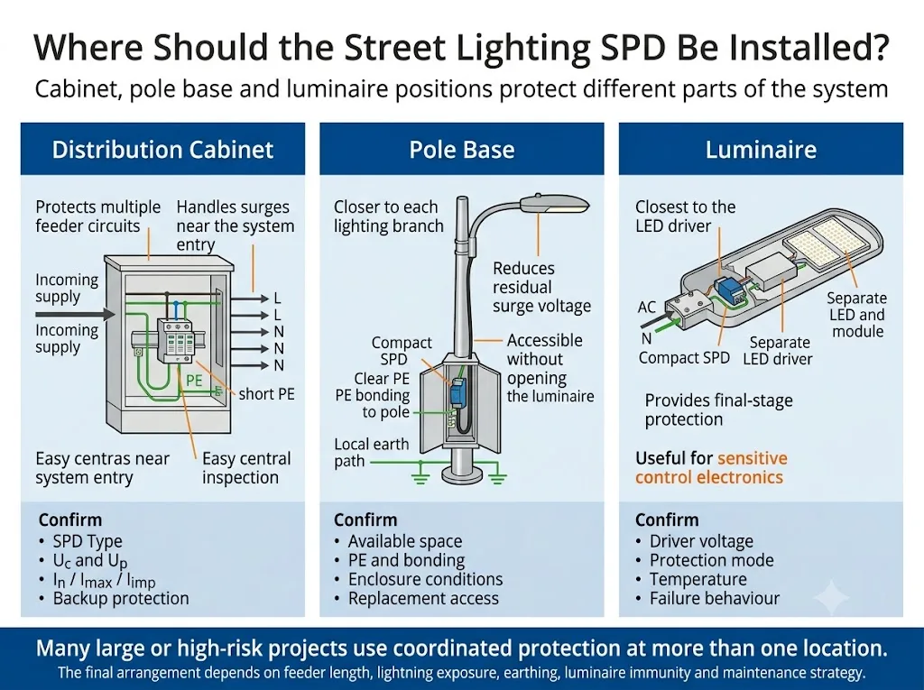
Un SPD nel quadro di distribuzione protegge la linea di alimentazione e diversi circuiti di illuminazione. Un SPD alla base del palo riduce lo stress da sovratensione vicino al singolo palo. Un SPD per l'apparecchio di illuminazione fornisce una protezione finale vicino al driver LED. Linee di alimentazione lunghe, linee aeree, elevata esposizione ai fulmini, controlli smart o obiettivi di manutenzione impegnativi possono giustificare una protezione coordinata in più posizioni.[3][4][7][13]
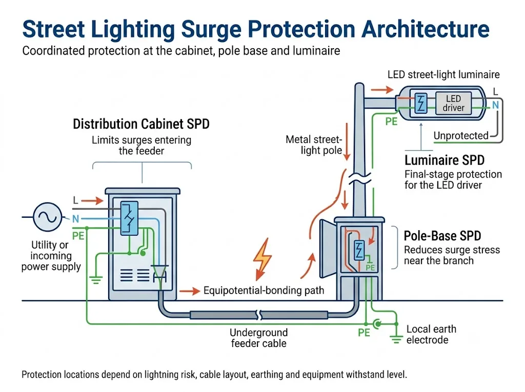
| Posizione SPD | Cosa protegge | Quando diventa importante | L'acquirente deve confermare |
|---|---|---|---|
| Quadro di distribuzione | Linea di alimentazione in ingresso e molteplici circuiti di illuminazione a valle | Alimentazione centrale, ingresso aereo, LPS esterno o alta esposizione | Tipo SPD, Uc, Up, capacità di scarica, modalità e protezione di backup |
| Scomparto alla base del palo | Singolo palo, connessione di derivazione e cavo che sale all'apparecchio di illuminazione | Linea di alimentazione lunga, pali distanziati o sostituzione in campo accessibile | Spazio, PE/equipotenzialità, cablaggio, custodia e accesso per manutenzione |
| All'interno o vicino all'apparecchio di illuminazione | Driver LED, apparecchiatura di controllo e ingresso finale dell'apparecchiatura | Driver sensibile, cablaggio lungo del palo o immunità specifica dell'apparecchio | Tensione di ingresso, Up, classe di isolamento, temperatura e modalità di guasto |
| Protezione coordinata | Suddivide il carico di sovratensione tra i dispositivi a monte e a valle | Strade comunali, parchi industriali, aeroporti e progetti ad alta disponibilità | Coordinamento, lunghezza della connessione, percorso della corrente e resistenza dell'apparecchiatura |
Conclusione del progetto: definire innanzitutto la posizione di protezione e il carico di sovratensione previsto. Selezionare il modello di SPD solo dopo che tali due questioni sono state chiarite.
In che modo le sovratensioni raggiungono un sistema di illuminazione stradale a LED?
L'illuminazione stradale combina driver elettronici sensibili con lunghi conduttori esterni. Un transitorio può arrivare attraverso l'alimentazione, essere indotto in una linea di alimentazione, verificarsi durante la commutazione o svilupparsi da differenze di potenziale tra parti separate dell'installazione.
Sovratensioni condotte attraverso l'alimentazione in ingresso
Un transitorio può entrare nel quadro di distribuzione dell'illuminazione e proseguire lungo diversi circuiti in uscita. La protezione all'origine della linea di alimentazione può ridurre lo stress trasmesso ai pali a valle.
Sovratensioni indotte in lunghi cavi esterni
I fulmini nelle vicinanze possono indurre tensione nei conduttori aerei e sotterranei. Un lungo cavo tra il quadro e un apparecchio remoto può anche aumentare la tensione rilevata dall'apparecchiatura dopo che l'SPD a monte è intervenuto.
Differenze di potenziale tra pali e apparecchiature remote
Un fulmine nelle vicinanze può sollevare il potenziale elettrico attorno a un palo metallico rispetto a un quadro remoto o a un altro palo. Pertanto, l'SPD, il conduttore PE, il collegamento del palo e la disposizione della messa a terra devono essere valutati come un unico percorso di corrente.[5][6]
Transitori di commutazione e legati ai guasti
Contattori, trasformatori, eliminazione dei guasti e gruppi di apparecchi di illuminazione commutati insieme possono produrre sovratensioni transitorie anche in assenza di un fulmine.
Un SPD per apparecchio di illuminazione non è un sistema di protezione esterno contro i fulmini. Limita la sovratensione transitoria e devia la corrente di scarica entro la sua capacità di test dichiarata. La gestione del rischio di fulminazione, la protezione fisica contro i fulmini, il collegamento equipotenziale e la messa a terra richiedono comunque una valutazione a livello di progetto.[4][5][6]
Quadro, base del palo o apparecchio di illuminazione: qual è la funzione di ogni posizione?
1. SPD nel quadro di distribuzione dell'illuminazione
Il quadro è normalmente il primo punto di protezione coordinata per l'alimentazione dell'impianto di illuminazione. Un SPD in questa posizione può limitare una sovratensione prima che questa venga distribuita a diversi pali.
Questa posizione è particolarmente importante quando la linea in entrata è aerea, quando un sistema esterno di protezione dai fulmini crea un possibile percorso per la corrente di fulmine, o quando un quadro alimenta molti apparecchi di illuminazione di valore.
Significato dell'acquirente: confermare il carico di sovratensione a monte previsto, il sistema di messa a terra, la protezione di backup e le condizioni di cortocircuito del quadro. Non scegliere l'SPD del quadro basandosi solo sul numero di luci collegate.
2. SPD nel vano alla base del palo
La posizione alla base del palo è più vicina all'apparecchio di illuminazione rispetto al quadro di distribuzione. Può limitare la sovratensione residua vicino alla derivazione e ridurre la tensione aggiuntiva sviluppata lungo la sezione finale del cavo.
La base del palo può essere anche più facile da ispezionare e sostituire rispetto a un modulo sigillato all'interno dell'apparecchio di illuminazione. Lo spazio disponibile, la curvatura del cavo, il collegamento PE o al palo, il drenaggio e la protezione ambientale devono comunque essere verificati.
Significato dell'acquirente: richiedere le dimensioni esatte, la disposizione dei terminali e il metodo di sostituzione. Una foto di un prodotto compatto non prova che il dispositivo possa essere installato in sicurezza nel vano del palo disponibile.
3. SPD all'interno o immediatamente accanto all'apparecchio di illuminazione
Un SPD compatto vicino all'ingresso del driver LED fornisce una protezione di stadio finale. Questo è utile quando l'elettronica sensibile si trova a una distanza significativa dall'SPD a monte.
L'ingombro fisico non è sufficiente. Il modulo deve essere compatibile con l'ingresso del driver, la classe di isolamento dell'apparecchio, le modalità di protezione, la temperatura interna e il comportamento richiesto a fine vita. La norma IEC 60598-1:2024 contiene i requisiti generali di sicurezza per gli apparecchi di illuminazione e include disposizioni pertinenti per i componenti di protezione contro le sovratensioni.[10]
Significato dell'acquirente: approvare l'SPD insieme al cablaggio del driver e dell'apparecchio di illuminazione. Non approvarlo come accessorio non correlato.
Quando è sufficiente un solo stadio SPD?
Un'installazione compatta in una strada privata o in un parco con alimentazione sotterranea, linea breve ed esposizione moderata può utilizzare una configurazione più semplice. Un lungo percorso municipale con molti pali separati, linee in entrata esposte o costosi apparecchi intelligenti potrebbe richiedere più di uno stadio coordinato.
La norma IEC 61643-12 copre la selezione, la posizione e il coordinamento degli SPD. La norma IEC 62305-4 tratta le misure di protezione contro le sovratensioni come un sistema piuttosto che come un insieme di dispositivi isolati.[3][7]
Illuminazione privata compatta
Condizione tipica: alimentazione sotterranea, percorso breve ed esposizione moderata.
Punto di partenza: protezione nel quadro, seguita da una verifica dell'immunità del driver e della lunghezza del cavo.
Linea di alimentazione municipale lunga
Condizione tipica: molti pali metallici separati e lunghe distanze di derivazione.
Punto di partenza: protezione coordinata nel quadro e alla base del palo o nell'apparecchio.
Percorso aereo o ad alto rischio
Condizione tipica: ingresso aereo, LPS esterno, torri faro o elevata esposizione ai fulmini.
Punto di partenza: valutare il carico di corrente di fulmine a monte e coordinare la protezione a valle.
Il numero di stadi SPD dovrebbe seguire il percorso della sovratensione, la disposizione dei cavi, il livello di resistenza dell'apparecchiatura e le conseguenze di un guasto. Non dovrebbe essere fissato da una regola generica di “un SPD per palo” o “protezione a tre stadi per ogni progetto”.
Come dovrebbe essere selezionata la disposizione SPD in un progetto di illuminazione esterna?
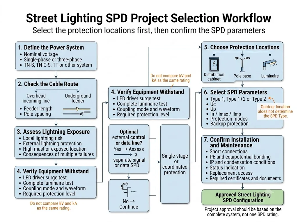
- Definire il sistema elettrico.
Registrare la tensione nominale, la tensione operativa massima, la frequenza, la disposizione delle fasi e il tipo di sistema di messa a terra TN-S, TN-C-S, TT o altro. - Mappare il percorso fisico.
Mostrare l'alimentazione in entrata, la posizione del quadro, i cavi aerei o sotterranei, le lunghezze delle linee di alimentazione, la spaziatura dei pali e ogni cavo di controllo o dati esterno. - Valutare l'esposizione.
Controllare la valutazione del rischio di fulminazione, l'LPS esterno, le strutture ad alta torre, i percorsi esposti e il costo operativo di guasti multipli simultanei. - Verificare le evidenze di resistenza dell'apparecchiatura.
Ottenere lo standard di test di sovratensione del driver LED o dell'apparecchio completo, il livello, il modo di accoppiamento, l'impedenza della sorgente, il numero di impulsi e i criteri di superamento del test. - Scegliere le posizioni di protezione.
Decidere cosa deve essere gestito nel quadro, cosa deve essere limitato al palo e se è necessario un SPD finale vicino al driver. - Selezionare e coordinare i dispositivi.
Controllare il tipo di SPD, Uc, Up, In, Imax o Iimp, le modalità di protezione, la protezione di backup, la lunghezza del collegamento e il comportamento a fine vita. - Approvare l'installazione e la manutenzione.
Verificare le condizioni dell'involucro, il collegamento equipotenziale, l'instradamento dei conduttori, l'indicazione dello stato, l'accesso per la sostituzione e la documentazione specifica del modello.
Il progetto deve utilizzare Tipo 1, Tipo 1+2 o Tipo 2?
L'installazione all'aperto da sola non determina il tipo di SPD. Il carico di sovratensione previsto e il percorso della corrente nella posizione di installazione determinano la classificazione richiesta.
Tipo 1 o Tipo 1+2
Valutare la capacità di scarica di fulmine di Tipo 1 laddove una corrente di fulmine parziale possa penetrare nell'impianto a bassa tensione. Ciò può verificarsi all'origine dell'impianto associata a un sistema di protezione esterno (LPS), a una linea aerea esposta o a un altro percorso identificato per la corrente di fulmine. La decisione deve seguire la valutazione del rischio del progetto e le norme di installazione applicabili.[4][5][6][8]
Tipo 2
Gli SPD di Tipo 2 sono comunemente usati dove si prevedono sovratensioni indotte da fulmini e transitori di commutazione, ma non carichi diretti da corrente di fulmine. Possono essere installati in un quadro di illuminazione, in un vano alla base del palo o vicino all'apparecchio di illuminazione quando le istruzioni del prodotto dichiarate consentono tale applicazione.
Dispositivi vicini all'apparecchiatura o combinati
Un modulo compatto per apparecchi di illuminazione può essere dichiarato come Tipo 2, Tipo 2+3 o un'altra configurazione testata. La classificazione non può essere dedotta dalle dimensioni fisiche o da un singolo valore di kV stampato.
La norma IEC 61643-01:2024 contiene i requisiti generali e i metodi di prova per gli SPD. La norma IEC 61643-11:2025 aggiunge i requisiti specifici per gli SPD collegati ai sistemi di alimentazione in bassa tensione in corrente alternata. L'approvazione del modello dovrebbe considerare sia il quadro normativo generale che quello specifico dell'applicazione, ove applicabile.[1][2]
Quali parametri influenzano la decisione per l'illuminazione stradale?
| Parametro | Cosa significa | Verifica del progetto |
|---|---|---|
| Uc / MCOV | Tensione massima di funzionamento continuativo che l'SPD può sopportare in servizio normale | Far corrispondere la tensione reale del circuito, la fluttuazione consentita, il sistema di messa a terra ed eventuali sovratensioni temporanee |
| Su | Tensione che si manifesta ai capi dell'SPD nelle condizioni di prova dichiarate | Coordinarlo con la resistenza del driver o dell'apparecchio di illuminazione e includere la tensione dei cavi di collegamento |
| In / Imax | Valori nominali della corrente di scarica associati a una forma d'onda 8/20 μs | Confrontare la forma d'onda, la modalità di protezione, la classificazione della prova e il numero di poli |
| Iimp | Valore nominale della corrente impulsiva utilizzato per il servizio di Tipo 1, comunemente associato a una forma d'onda 10/350 μs | Specificarlo solo dove la valutazione dell'installazione identifica un rischio di corrente da fulmine |
| Modalità di protezione | Percorsi protetti come L-N, L-PE e N-PE | Far corrispondere il sistema di messa a terra, la classe di isolamento dell'apparecchio di illuminazione e i percorsi effettivi delle sovratensioni |
| Comportamento in caso di guasto | Cosa succede quando l'SPD raggiunge la fine della sua vita utile | Confermare la continuità del carico, la disconnessione, l'indicazione visiva e i requisiti del contatto remoto |
Un test di immunità dell'apparecchio di illuminazione a 10 kV e un valore nominale di corrente di scarica dell'SPD a 10 kA descrivono prove diverse. Il valore in kV riguarda una prova di tensione applicata in condizioni definite. Il valore in kA riguarda la corrente gestita con una specifica forma d'onda. Non sono intercambiabili.[1][2][9]
La selezione dettagliata di Uc, Up, In, Imax, Iimp e della protezione di backup dovrebbe essere completata attraverso le specifiche SPD di progetto, piuttosto che estesa in un tutorial generale sui parametri in questa pagina.
In che modo il driver LED, la messa a terra e le condizioni ambientali esterne influenzano la scelta?
Confermare le condizioni di prova complete dell'apparecchio di illuminazione
Un'affermazione come “protetto a 10 kV” è incompleta. Richiedere lo standard di prova, la modalità di accoppiamento, l'impedenza della sorgente, il numero e la polarità degli impulsi, lo stato operativo e i criteri di superamento. La norma IEC 61000-4-5 fornisce un metodo generale di immunità alle sovratensioni. La norma ANSI C136.2-2023 affronta i requisiti di tenuta dielettrica e immunità ai transitori per le apparecchiature di illuminazione stradale e di aree esterne nordamericane.[9][12]
Non dare per scontato che la protezione interna del driver sostituisca un SPD esterno
Un driver LED può contenere un MOV o un altro componente per sovratensioni. La sua capacità energetica, la disconnessione termica e il comportamento a fine vita possono differire da quelli di un SPD testato separatamente. Confermare come il driver, la fotocellula, il modulo di controllo e il dispositivo esterno condividono lo stress da sovratensione.
Far corrispondere la costruzione dell'apparecchio di illuminazione di Classe I o Classe II
Le disposizioni di messa a terra protettiva e isolamento differiscono. Le modalità di protezione dell'SPD e il metodo di collegamento devono corrispondere all'apparecchio di illuminazione completo e alle sue istruzioni approvate. Non aggiungere un collegamento PE a un assemblaggio di Classe II a meno che il design approvato non lo consenta.[10][13]
Mantenere il percorso della corrente di sovratensione breve e controllato
Collegamenti lunghi o indiretti aggiungono tensione durante una sovratensione rapida. Mantenere il percorso dell'SPD compatto, separare i conduttori protetti da quelli non protetti e coordinare il percorso PE o di collegamento con il progetto dell'installazione.[3][8]
Valutare l'involucro esterno completato
Il modulo SPD e l'installazione esterna completata sono diversi. Un SPD su guida DIN può essere adatto all'interno di un armadio o di un vano palo progettato correttamente, anche quando non è destinato all'esposizione diretta agli agenti atmosferici.
La norma IEC 60529 classifica la protezione IP dell'involucro. Non conferma di per sé il controllo della condensa, la resistenza ai raggi UV, la resistenza alla corrosione, il drenaggio, la qualità dei pressacavi o una temperatura interna accettabile.[11]
La norma IEC 60364-7-714 si applica a molte installazioni di illuminazione esterna fisse, ma il suo ambito di applicazione pubblicato esclude le installazioni di illuminazione pubblica che fanno parte della rete elettrica pubblica. I progetti municipali devono verificare le specifiche del gestore di rete, le normative nazionali e i requisiti contrattuali.[14]
Cosa cambia in un progetto di illuminazione stradale intelligente (smart)?
Proteggere l'alimentazione CA non protegge automaticamente ogni interfaccia esterna. L'illuminazione intelligente può includere fotocellule, controllo DALI o 0–10 V, RS485, Ethernet, PoE, comunicazione PLC, sensori, telecamere o un gateway remoto.
Ogni cavo che lascia l'area dell'apparecchiatura protetta può creare un altro percorso per le sovratensioni. Confermare la tensione di interfaccia, il tipo di segnale, la velocità dati, la schermatura, il riferimento di messa a terra e l'alimentazione PoE prima di selezionare un protettore di segnale o dati. Un SPD di potenza non può sostituire un protettore di segnale abbinato all'interfaccia.
Cosa si deve verificare sull'SPD effettivo e sui documenti di approvazione?
Un articolo tecnico può spiegare la logica di selezione, ma l'approvazione finale del progetto richiede prove specifiche per il modello. Non approvare un SPD per illuminazione stradale basandosi su un'infografica, una foto del prodotto o un singolo valore in kA.
- Identificazione completa del prodotto: modello esatto, modalità di protezione, schema di cablaggio e dimensioni.
- Scheda tecnica specifica del modello: Uc, Up, In, Imax o Iimp, protezione di backup e limiti ambientali.
- Istruzioni per l'installazione: gamma di conduttori, coppia dei morsetti, lunghezza del collegamento e limiti di montaggio.
- Ambito del rapporto di prova o del certificato: verificare che il modello esatto o la serie dichiarata siano coperti.
- Indicazione di fine vita: disconnessione termica, indicazione visiva, continuità del carico e logica del contatto remoto.
- Documentazione di coordinamento dell'apparecchio di illuminazione: condizioni di prova di sovratensione del driver o dell'apparecchio di illuminazione completo e criteri di accettazione.
- Informazioni sull'approvazione OEM: contenuto dell'etichetta, tracciabilità, imballaggio, approvazione del campione e versione del documento.
Laddove un progetto richieda un modulo compatto per apparecchio di illuminazione, un SPD alla base del palo o una configurazione OEM personalizzata, richiedere un campione fisico e approvarlo con il driver, l'involucro, il cablaggio e i dispositivi di protezione reali prima di procedere con l'ordine all'ingrosso.
Errori comuni nell'SPD per l'illuminazione stradale
- Utilizzo di un solo SPD nell'armadio per una lunga rete distribuita senza controllare la tensione che raggiunge gli apparecchi di illuminazione remoti.
- Definire ogni SPD per esterni come Tipo 1 senza identificare un percorso per la corrente da fulmine.
- Trattare 10 kV e 10 kA come valori nominali equivalenti.
- Scegliere il valore di Uc più alto disponibile senza verificare il livello di protezione risultante.
- Ignorare i percorsi di protezione in modo comune perché il driver dispone già di una protezione L-N.
- Assumere che un apparecchio di illuminazione di Classe II elimini ogni rischio legato alla differenza di potenziale.
- Aggiungere un SPD per uscita DC arbitrario senza verificare la tensione del driver e il coordinamento dell'isolamento.
- Dimenticare le linee di controllo e dati nei sistemi di illuminazione intelligente.
- Specificare un codice IP ignorando condensa, calore, pressacavi e corrosione.
- Omettere di definire la manutenzione e il comportamento a fine vita prima di approvare un progetto ampio e ripetitivo.
Lista di controllo per il progetto SPD di illuminazione stradale
Inviare questi dettagli prima di richiedere una raccomandazione sul modello. Senza di essi, una proposta da “10 kV” o “20 kA” potrebbe essere solo una congettura.
Hai bisogno di confermare una disposizione SPD per l'illuminazione stradale?
Condividere lo schema unifilare, i dati di alimentazione e messa a terra, il layout dall'armadio al palo, il livello di prova dell'apparecchio, lo spazio di installazione e i documenti richiesti. Una raccomandazione utile dovrebbe identificare le posizioni di protezione, il servizio SPD previsto ed eventuali condizioni che richiedono ancora un'approvazione a livello di progetto.
LEEYEE è un fornitore specializzato in protezione dalle sovratensioni e bassa tensione. CNSPD è la piattaforma di LEEYEE dedicata alla protezione dalle sovratensioni per gli acquirenti tecnici globali.
Domande frequenti sul progetto
Ogni lampione a LED necessita di un proprio SPD?
Non esiste una regola universale. Un SPD alla base del palo o nell'apparecchio diventa più prezioso quando il dispositivo a monte è lontano, la linea di alimentazione è lunga, l'esposizione ai fulmini è elevata, l'apparecchio è costoso o il progetto richiede una bassa manutenzione. Verificare il rischio dell'intero sistema e il coordinamento.
È preferibile installare l'SPD alla base del palo o all'interno dell'apparecchio di illuminazione?
La base del palo offre spesso un accesso più agevole, più spazio e un punto di collegamento equipotenziale pratico. Un SPD nell'apparecchio è più vicino al driver LED. La posizione migliore dipende dal livello di protezione efficace, dalla classe di isolamento, dalle condizioni dell'involucro e dalla strategia di manutenzione.
Se l'apparecchio supera un test a 10 kV, un SPD esterno non è necessario?
Non necessariamente. Verificare lo standard di prova, il modo di accoppiamento, l'impedenza della sorgente, il numero di impulsi, lo stato operativo e i criteri di superamento. Un risultato di immunità di laboratorio non rappresenta ogni sovratensione sul campo o evento di fulminazione diretta.
Ogni armadio per illuminazione stradale dovrebbe utilizzare un SPD di Tipo 1?
Il dispositivo di Tipo 1 è collegato al percorso previsto per la corrente di fulmine. Molte installazioni utilizzano una protezione di Tipo 2 laddove si prevedono solo sovratensioni indotte e da commutazione. Un sistema di protezione contro i fulmini (LPS) esterno, un ingresso aereo o altri percorsi identificati per la corrente di fulmine possono giustificare l'impiego di un Tipo 1 o di un Tipo 1+2 a seguito di una valutazione.
Un SPD IP65 risolve tutti i rischi delle installazioni esterne?
No. L'IP descrive la protezione dell'involucro in condizioni definite. Temperatura, condensa, raggi UV, corrosione, pressacavi, drenaggio e accesso sicuro per la manutenzione richiedono comunque una conferma per l'installazione completata.
Quali documenti dovrebbe richiedere un OEM o un acquirente di progetto?
Richiedere la scheda tecnica completa, le istruzioni di installazione, il certificato o rapporto di prova del modello esatto, le modalità di protezione, i valori di Uc, Up, le correnti di scarica, i dati di protezione di backup, i limiti ambientali, le dimensioni, il comportamento a fine vita e l'evidenza delle prove di sovratensione per il driver o l'intero apparecchio.
Riferimenti
- Commissione Elettrotecnica Internazionale. IEC 61643-01:2024, Dispositivi di protezione da sovratensioni a bassa tensione - Parte 01: Requisiti generali e metodi di prova.
- Commissione Elettrotecnica Internazionale. IEC 61643-11:2025, Dispositivi di protezione contro le sovratensioni a bassa tensione - Parte 11: Dispositivi di protezione contro le sovratensioni collegati a sistemi di alimentazione a bassa tensione in corrente alternata - Requisiti e metodi di prova.
- Commissione Elettrotecnica Internazionale. IEC 61643-12:2020, Dispositivi di protezione contro le sovratensioni a bassa tensione - Parte 12: Principi di selezione e applicazione.
- Commissione Elettrotecnica Internazionale. IEC 62305-2:2024, Protezione contro i fulmini - Parte 2: Valutazione del rischio.
- Commissione Elettrotecnica Internazionale. IEC 62305-3:2024, Protezione contro i fulmini - Parte 3: Danni materiali alle strutture e pericolo per le persone.
- Commissione Elettrotecnica Internazionale. IEC 62305-4:2024, Protezione contro i fulmini – Parte 4: Sistemi elettrici ed elettronici all'interno delle strutture.
- Commissione Elettrotecnica Internazionale. IEC 61643-12:2020, Principi di selezione, posizionamento e coordinamento degli SPD.
- Commissione Elettrotecnica Internazionale. IEC 60364-5-53:2019+AMD1:2020+AMD2:2024 CSV, Impianti elettrici a bassa tensione - Parte 5-53: Scelta ed installazione dei componenti elettrici.
- Commissione Elettrotecnica Internazionale. IEC 61000-4-5:2014+AMD1:2017 CSV, Compatibilità elettromagnetica - Parte 4-5: Prove di immunità ai transitori (surge).
- Commissione Elettrotecnica Internazionale. IEC 60598-1:2024, Apparecchi di illuminazione - Parte 1: Requisiti generali e prove.
- Commissione Elettrotecnica Internazionale. IEC 60529:1989+AMD1:1999+AMD2:2013 CSV, Gradi di protezione degli involucri (Codice IP).
- ANSI / NEMA. ANSI C136.2-2023, Apparecchiature per l'illuminazione stradale e di aree esterne – Requisiti di tenuta dielettrica e immunità ai transitori elettrici.
- DEHN. Concetto di protezione contro le sovratensioni per lampioni LED, SD 86/E. Guida all'applicazione che illustra le possibili posizioni degli SPD in un quadro di alimentazione, alla base del palo e nell'apparecchio di illuminazione. I valori di progetto devono essere verificati rispetto agli standard vigenti e ai documenti modello.
- Commissione Elettrotecnica Internazionale. IEC 60364-7-714:2011, Impianti elettrici a bassa tensione - Impianti di illuminazione esterna.
