
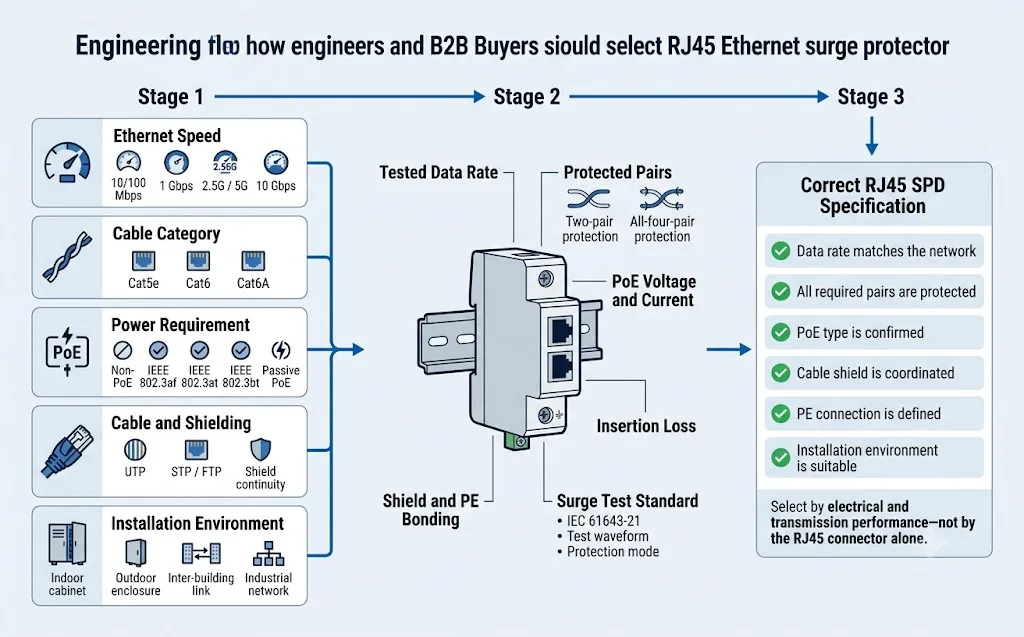
Due limitatori di sovratensione possono usare entrambi prese RJ45 e tuttavia essere elettricamente incompatibili. Prima di ordinare, conferma la reale velocità Ethernet, la categoria del cavo, il requisito PoE, le coppie protette, la schermatura, la messa a terra, le condizioni del test di sovratensione e l’ambiente di installazione.
Indice dei contenuti
Risposta rapida
Per un rete non PoE da 100Mbps, selezionare uno SPD per linea dati RJ45 a bassa capacità adatto alla tensione di esercizio e alle coppie di conduttori attive. Per Ethernet Gigabit 1000BASE-T, l'SPD deve preservare tutte e quattro le coppie twistate ed essere testato per la velocità dati richiesta. Per PoE, deve inoltre trasportare la corretta tensione continua e la corretta corrente continua senza interrompere la trasmissione dei dati o causare un'eccessiva caduta di tensione.
Che cos’è un limitatore di sovratensione RJ45?
Un Protezione da sovratensioni RJ45 viene installato in serie a un cavo Ethernet per limitare le sovratensioni transitorie prima che raggiungano uno switch, un router, un server, un controller industriale, un access point, un terminale di rete o un'altra porta RJ45.
A differenza di un SPD per la distribuzione di potenza, un SPD Ethernet deve proteggere i conduttori di segnale sensibili preservando al contempo la larghezza di banda di rete, il bilanciamento delle coppie e l'impedenza necessari per la comunicazione. Una versione PoE deve inoltre trasportare alimentazione CC continua alla tensione e alla corrente corrette.
Un connettore RJ45 descrive solo l'interfaccia fisica. Non garantisce che il dispositivo di protezione supporti Gigabit Ethernet, Cat6A, PoE o tutte e quattro le coppie intrecciate.
Quale limitatore di sovratensione RJ45 dovresti scegliere?
Iniziare dai requisiti di rete. Non basarsi sull'aspetto dell'alloggiamento RJ45 o sul valore di corrente di picco più elevato dichiarato dal fornitore.
| Requisiti di rete | Configurazione SPD minima | Parametri da verificare | Rifiutare il modello quando |
|---|---|---|---|
| 10/100Mbps, non-PoE Fast Ethernet | SPD per linea dati RJ45 adattato alla tensione di segnale e alla configurazione delle coppie attive. | Velocità dati massima, Uc, pin protetti, perdita di inserzione, messa a terra e forma d'onda del test di sovratensione. | Il fornitore non è in grado di identificare i pin protetti o li descrive solo come un dispositivo di protezione per linee telefoniche o segnali generici. |
| 1000BASE-T, non-PoE Gigabit | SPD RJ45 a quattro coppie con prestazioni confermate a 1000 Mbps. | Velocità dati testata, intervallo di frequenza, perdita di inserzione, perdita di ritorno, bilanciamento delle coppie e continuità di tutti gli otto conduttori. | Protegge solo i pin 1–2 e 3–6, oppure la sua velocità di trasmissione massima documentata è di 100 Mbps. |
| Cat6A / 10GBASE-T Larghezza di banda elevata | Un modello specificamente validato per le prestazioni di canale Cat6A o 10G richieste. | Frequenza testata, perdita di inserzione, perdita di ritorno, diafonia, impedenza e certificazione del canale completato. | L'unica prova è un connettore Cat6A, un alloggiamento in metallo o un'etichetta "compatibile 10G" non supportata. |
| PoE o PoE+ 802.3af / 802.3at | SPD compatibile PoE abbinato alla velocità dati, alla tensione CC, alla corrente e alle coppie alimentate. | Standard PoE, supporto modalità A/B, mappatura delle coppie, corrente di carico, resistenza CC, caduta di tensione e aumento di temperatura. | È classificato esclusivamente per segnali dati a bassa tensione o il fornitore non è in grado di confermare la corrente PoE continua. |
| PoE++ / 4PPoE 802.3bt | SPD a quattro coppie specificamente convalidato per il livello di potenza di Tipo 3 o Tipo 4 richiesto. | Potenza massima della sorgente, corrente per coppia, temperatura del connettore, caduta di tensione, continuità a quattro coppie e larghezza di banda. | Il modello riporta solo la dicitura “compatibile PoE” senza specificare lo standard 802.3bt, l'alimentazione a quattro coppie o la capacità di corrente. |
| Armadio di rete con numerose linee Multi-porta | Protezione rack o multi-porta con un percorso di messa a terra e collegamento di schermatura progettato. | Conteggio porte, collegamento a terra, continuità di schermatura, gestione dei cavi e dati di trasmissione per canale. | Viene utilizzata una specifica generale per ogni porta, ma non sono disponibili informazioni elettriche o di trasmissione per singolo canale. |
Cat5e, Cat6 o Cat6A influenzano la selezione dell’SPD RJ45?
Sì, ma l'etichetta del cavo è solo il punto di partenza. Una volta inseriti un SPD e i relativi cavi patch, questi diventano parte integrante del canale di trasmissione completo.
| Categoria di cablaggio | Frequenza di riferimento | Applicazione comune | Ciò che l'SPD deve preservare |
|---|---|---|---|
| Cat5e | Up to 100MHz | 100Mbps and 1000BASE-T | Percorsi dati a due o quattro coppie richiesti, bilanciamento dell'impedenza, perdita di inserzione e perdita di ritorno. |
| Cat6 | Up to 250MHz | Gigabit Ethernet e alcune applicazioni a velocità superiore entro i limiti di sistema | Tutte e quattro le coppie per Gigabit, larghezza di banda sufficiente, diafonia controllata e prestazioni del canale verificate. |
| Cat6A | Up to 500MHz | Cablaggio strutturato 10GBASE-T | Prestazioni di canale di livello Cat6A: non semplicemente una presa o un involucro schermato in stile Cat6A. |
Corrispondenza delle prestazioni testate
- Confermare la velocità effettiva richiesta dallo switch e dal dispositivo.
- Richiedere la frequenza di trasmissione testata dell'SPD.
- Verificare la perdita di inserzione alla frequenza pertinente.
- Controllare la continuità di tutti gli otto conduttori per il Gigabit.
- Testare il collegamento completato dopo l'installazione dell'SPD.
Affidarsi al nome del prodotto
- “RJ45” non significa automaticamente Gigabit.
- Un “alloggiamento Cat6” non garantisce un risultato di canale Cat6.
- Un involucro metallico non prova la continuità della schermatura.
- Una bassa perdita a 100 MHz non garantisce prestazioni a 500 MHz.
- Un'asserzione di 10G priva di condizioni di test non costituisce prova di progetto.
Perché uno SPD RJ45 errato può ridurre un collegamento Gigabit a 100Mbps?
Lo standard 100BASE-TX utilizza normalmente due coppie intrecciate per i dati. Il 1000BASE-T ne utilizza tutte e quattro. Un dispositivo di protezione che non preservi ogni coppia richiesta può impedire il funzionamento in Gigabit o causare la negoziazione del collegamento a una velocità inferiore.
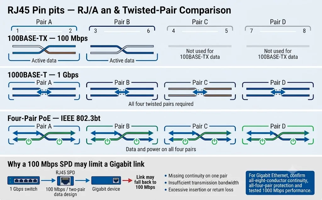
Due coppie di dati
Lo standard 100BASE-TX trasmette solitamente i dati tramite coppie sui pin 1–2 e 3–6. Non si deve dare per scontato che un dispositivo di protezione progettato esclusivamente per questa configurazione supporti il Gigabit Ethernet.
Tutte e quattro le coppie
Lo standard 1000BASE-T utilizza tutte e quattro le coppie intrecciate. Qualsiasi coppia mancante, instradata in modo errato o scarsamente bilanciata può impedire la creazione di un collegamento Gigabit o causare un funzionamento instabile.
Requisiti di integrità del segnale più elevati
Alle frequenze più elevate, la capacità parassita, la discontinuità di impedenza, la perdita di ritorno e la diafonia diventano più critiche. Utilizzare esclusivamente un SPD specificamente convalidato.
Gli scaricatori di sovratensione RJ45 PoE e non PoE non sono intercambiabili
Un modello non PoE può proteggere solo i circuiti dati a bassa tensione. Un modello PoE deve preservare la trasmissione Ethernet trasportando al contempo corrente continua attraverso le coppie di conduttori richieste.
| Tipo PoE | Designazione IEEE | Potenza massima della sorgente | Utilizzo tipico delle coppie | Cosa deve confermare l'acquirente SPD |
|---|---|---|---|---|
| PoE Tipo 1 | IEEE 802.3af | Up to 15.4W | Solitamente due coppie alimentate | Modalità PoE, tensione, corrente, assegnazione delle coppie e velocità di trasmissione dati. |
| PoE+ Tipo 2 | IEEE 802.3at | Up to 30W | Solitamente due coppie alimentate | Corrente continua, riscaldamento del connettore, resistenza e caduta di tensione. |
| PoE++ Tipo 3 | IEEE 802.3bt | Up to 60W | Due o quattro coppie alimentate a seconda dell'implementazione | Supporto esplicito per il Tipo 3 e l'effettiva disposizione delle coppie alimentate. |
| PoE++ Tipo 4 | IEEE 802.3bt | Up to 90W | Quattro coppie alimentate | Alimentazione a quattro coppie, corrente per coppia, aumento di temperatura e caduta di tensione. |
| PoE Passivo | Specifico del fornitore | Dipende dal sistema | Polarità e assegnazione dei pin fisse | Tensione CC esatta, polarità, mappatura dei pin, corrente e compatibilità del dispositivo. |
Per sistemi IEEE PoE
- Verificare 802.3af, 802.3at o 802.3bt.
- Verificare la compatibilità con Modalità A, Modalità B e a quattro coppie.
- Verificare la tensione e la corrente continua massima.
- Verificare la resistenza CC e la caduta di tensione prevista.
- Verificare la velocità dei dati separatamente dalla dichiarazione PoE.
Per sistemi PoE passivi
- Registrare l'esatta tensione iniettata.
- Registrare le assegnazioni dei pin positivi e negativi.
- Confermare la corrente di carico massima.
- Non dare per scontata la negoziazione PoE automatica.
- Richiedere l'approvazione scritta per il cablaggio esatto.
Un cavo RJ45 schermato non sostituisce la connessione di terra dell’SPD
La schermatura del cavo, il guscio metallico RJ45 e il terminale SPD PE hanno funzioni correlate ma distinte. Devono essere coordinati con il sistema di collegamento equipotenziale locale del sito.
Controlla l'accoppiamento elettromagnetico
La schermatura contribuisce a gestire le interferenze elettromagnetiche quando viene terminata e collegata correttamente in conformità con il cablaggio strutturato e la progettazione EMC.
Mantiene la continuità della schermatura
Una presa schermata può trasportare la schermatura del cavo attraverso il protettore, tuttavia la continuità della schermatura deve essere confermata e non data per scontata.
Devia la corrente di sovratensione
L'SPD necessita di un collegamento breve e a bassa impedenza al sistema equipotenziale locale. Un conduttore di protezione (PE) lungo aggiunge tensione induttiva.
Consigliato
- Collegare l'SPD allo stesso sistema PE locale dell'apparecchiatura protetta.
- Mantenere il collegamento di terra breve e diretto.
- Verificare la continuità della schermatura quando si utilizzano cavi schermati.
- Separare i cavi protetti dai cavi esposti in ingresso.
- Attenersi al progetto di compatibilità elettromagnetica (EMC) e di collegamento equipotenziale.
Evitare
- Trattare la schermatura del cavo come unico percorso di scarica.
- Collegare l'SPD a un dispersore di terra isolato e remoto, non correlato al sistema PE locale.
- Utilizzare un conduttore di terra eccessivamente lungo o indiretto.
- Far passare cavi protetti e non protetti insieme.
- Supponendo che ogni involucro metallico abbia lo stesso collegamento equipotenziale interno.
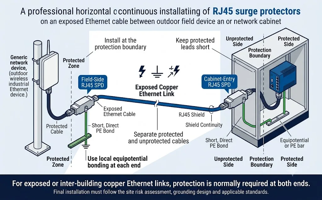
L’SPD RJ45 deve essere installato sul dispositivo, sullo switch o nel cabinet?
Installarlo nel punto in cui il cavo esposto attraversa la zona protetta e il più vicino possibile all'ingresso dell'apparecchiatura o dell'armadio da proteggere.
| Scenario di installazione | Posizione di protezione consigliata | Motivo |
|---|---|---|
| Cavo esterno in ingresso in un edificio | Al limite di ingresso del cavo prima che venga instradato attraverso la zona protetta dell'edificio. | Riduce l'energia di sovratensione trasportata nel cablaggio di rete interno. |
| Ethernet in rame tra edifici | In entrambi i punti di ingresso dell'edificio, collegati al sistema equipotenziale locale di ciascun edificio. | Entrambe le estremità possono essere soggette a diverse condizioni di sovratensione e potenziale di terra. |
| Dispositivo di rete da esterno o da tetto | In prossimità del dispositivo di campo e nuovamente all'ingresso dell'edificio o dell'armadio. | Protegge le apparecchiature sensibili su entrambe le estremità del percorso esposto. |
| Mobile di controllo industriale | All'ingresso del cavo nell'armadio, prima che la linea raggiunga lo switch, il PLC, l'HMI o il controller. | Mantiene il lato delle sovratensioni in ingresso separato dall'elettronica sensibile. |
| Rack di rete multiporta | In prossimità del patch panel o dello switch utilizzando un rack organizzato o una protezione multicanale. | Fornisce una protezione centralizzata e un percorso di messa a terra progettato. |
| Collegamento di rete interno breve | Utilizzare una valutazione dei rischi del progetto invece di installare la protezione automaticamente. | Il rischio può essere inferiore quando l'intero collegamento rimane all'interno di una singola zona di protezione equipotenziale. |
Come evitare la perdita di velocità di rete e le interferenze del segnale
Il fatto che un collegamento diventi attivo non ne garantisce la piena compatibilità. Potrebbe connettersi a una velocità inferiore, accumulare errori CRC o diventare instabile durante il traffico reale e il carico PoE.
| Sintomo osservato | Possibile causa correlata all'SPD | Verifica consigliata |
|---|---|---|
| Il collegamento a 1 Gbps scende a 100 Mbps | Solo due coppie sono continue o il protettore è progettato per 100 Mbps. | Verificare tutti gli otto conduttori, la mappatura delle coppie e la velocità dati massima documentata. |
| Il collegamento si disconnette ripetutamente | Perdita eccessiva, discontinuità di impedenza, contatti difettosi o disturbi di messa a terra. | Ispezionare i connettori, i cavi di permutazione, i registri degli switch e i risultati dei test sui canali. |
| Aumento degli errori CRC o dei pacchetti | Perdita di ritorno, diafonia, squilibrio delle coppie o attenuazione ad alta frequenza. | Confrontare i contatori di errori prima e dopo l'installazione e certificare il canale completo. |
| Riavvio del dispositivo PoE sotto carico | Eccessiva resistenza CC, caduta di tensione, calore o corrente di carico insufficiente. | Misurare la tensione sul dispositivo alimentato e verificare la corrente nominale continua dell'SPD. |
| Solo alcuni dispositivi PoE funzionano | Supporto Modalità A/B errato, cablaggio PoE passivo o continuità delle coppie alimentate incompleta. | Verificare il PSE, il PD, l'assegnazione dei pin e lo schema delle coppie del protettore. |
| Il rumore appare dopo l'installazione | Terminazione della schermatura scadente, problemi di collegamento o accoppiamento tra cavi protetti e non protetti. | Verificare la continuità della schermatura, il percorso PE e la separazione fisica dei cavi. |
Registrare un valore di riferimento
- Velocità di collegamento negoziata.
- Stato della tensione e dell'alimentazione PoE.
- Contatori di errori e CRC della porta dello switch.
- Risultato della certificazione del cavo esistente.
Ripetere gli stessi controlli
- Confermare la stessa velocità negoziata.
- Verificare la presenza di nuovi errori di pacchetto o CRC.
- Testare il dispositivo sotto il carico PoE massimo.
- Certificare il canale completato quando richiesto.
Non limitarsi al test di continuità
- La continuità non dimostra l'ampiezza di banda.
- Un ping riuscito non dimostra il margine di segnale.
- La sola velocità di collegamento non rivela errori intermittenti.
- Utilizzare apparecchiature di test per reti e cablaggi appropriate.
Non confrontare gli SPD RJ45 solo in base a un valore nominale “5kV” o “10kV”
Un valore di sovratensione privo di forma d'onda, condizioni di origine, corrente, combinazione di conduttori e tensione di limitazione misurata non è sufficiente per un confronto tecnico.
| Parametro | Cosa comunica all'acquirente | Cosa deve essere confermato |
|---|---|---|
| Un | Tensione operativa nominale del circuito protetto. | Indica se il valore si applica ai conduttori dati, all'alimentazione PoE o a entrambi. |
| Uc / MCOV | Tensione operativa continua massima tollerabile dal dispositivo di protezione da sovratensioni (SPD). | Valori linea-linea, coppia-coppia e linea-terra, ove applicabili. |
| Tensione di limitazione / Up | Tensione residua sul lato protetto durante un test di sovratensione definito. | Forma d'onda di prova, livello di corrente, combinazione dei conduttori e modalità di protezione. |
| Corrente di impulso In | Prestazioni della corrente di sovratensione in base a una forma d'onda di corrente dichiarata. | Indica se il valore si riferisce al singolo conduttore, alla coppia, al canale o all'intero dispositivo. |
| D1 / prova a impulso di fulmine | Prestazioni a impulso di energia superiore quando dichiarate per SPD su linee di segnale. | Categoria di prova, forma d'onda, percorsi dei conduttori ed esatto modello testato. |
| Perdita di inserzione | Attenuazione del segnale introdotta dal protettore. | L'intervallo di frequenza in cui è stato misurato il valore. |
| Perdita di ritorno | Grado di mantenimento dell'impedenza caratteristica richiesta lungo il percorso del segnale. | Frequenza di test, categoria del canale e limite di test applicabile. |
| Coppie e modalità protette | Quali conduttori e combinazioni di conduttori ricevono protezione. | Coppia-coppia, conduttore-terra, schermo-terra e tutti i pin richiesti. |
| Normativa applicabile | Il quadro di riferimento per i test e la classificazione utilizzato per il prodotto. | Edizione standard, numero di rapporto, modello testato e ambito del rapporto. |
Quadro di riferimento IEC pertinente
La norma IEC 61643-21 riguarda gli SPD collegati a reti di telecomunicazione e di segnalazione, incluse le reti che forniscono alimentazione sulla stessa linea, come il PoE.
La norma IEC 61643-22 definisce i principi di selezione, posizionamento, funzionamento e coordinamento per gli SPD destinati alle telecomunicazioni e alla segnalazione.
Documenti da richiedere
- Scheda tecnica del modello specifico.
- Rapporto di prova IEC o di progetto applicabile.
- Schema dei pin RJ45 e del canale di protezione.
- Dati di test della trasmissione o del canale completo.
- Dati su corrente, resistenza e temperatura PoE.
- Istruzioni per l'installazione e la messa a terra.
Flusso di selezione del limitatore di sovratensione RJ45 per tecnici e acquirenti
Esegui questi sei controlli prima di richiedere un campione, approvare un modello sostitutivo o confrontare preventivi OEM.
Identifica la velocità di collegamento reale.
Leggi le specifiche dello switch e del dispositivo collegato. Non dedurre la velocità richiesta esclusivamente dall'etichetta del cavo.
Conferma se si tratta di PoE o non-PoE.
Registrare il tipo IEEE PoE o l'esatta tensione PoE passiva, la polarità e la corrente di carico.
Mappare le coppie di conduttori.
Confermare quali coppie trasportano dati e alimentazione e quali conduttori sono protetti dall'SPD.
Definire l'ambiente.
Specificare armadio da interno, custodia da esterno, dispositivo da tetto, percorso tra edifici o rete industriale.
Definire la messa a terra e il montaggio.
Confermare l'installazione in linea, a parete, su rack o in armadio e il metodo di messa a terra o collegamento equipotenziale locale.
Esaminare le prestazioni documentate.
Confrontare i dati di trasmissione, Uc, la tensione limite, la forma d'onda di sovratensione e il rapporto di prova del modello esatto.
Quale configurazione RJ45 LEEYEE attuale è adatta all’applicazione?
La seguente matrice è limitata alle configurazioni documentate nelle informazioni pubbliche sui prodotti e nei dati di catalogo LEEYEE correnti. Non implica la compatibilità con Gigabit, 10G o PoE++.
LY21-2 CAT1 / CAT4 / CAT8
Protezione del segnale di rete RJ45 per linee dati Ethernet non PoE.
- Tipo di rete
- Ethernet non PoE
- Velocità massima
- 100Mbps
- Tensione operativa
- 5V DC
- Uc massima
- 6V DC
- Corrente di carico
- 500mA
- Perdita di inserzione
- ≤0,2dB
- Grado di protezione
- IP20
CAT1, CAT4 e CAT8 sono etichette di configurazione del prodotto. Non devono essere interpretate come prestazioni di cablaggio Ethernet Cat1, Cat4 o Cat8.
Visualizza prodotto non PoELY21-2 PoE
Protezione combinata per circuiti di alimentazione PoE e dati Ethernet.
- Tipo di rete
- Alimentazione PoE + dati Ethernet
- Velocità massima
- 100Mbps
- Tensione continua (Uc) alimentazione PoE
- Fino a 60V CC
- Corrente di carico
- 500mA
- Tensione operativa dati
- 5V DC
- Perdita di inserzione
- ≤0,2dB
- Grado di protezione
- IP20
Verificare la tensione PoE, la modalità a coppie alimentate, la corrente continua e l'esatta configurazione dei pin prima di effettuare l'ordine. Non descrivere questo modello come compatibile con Gigabit o PoE++.
Conferma configurazione PoELY21-2 CAT16 / CAT24
Protezione RJ45 multiporta per armadi di rete centralizzati non PoE.
- Opzioni porta
- 16 porte / 24 porte
- Tipo di rete
- Ethernet non PoE
- Velocità massima
- 100Mbps
- Tensione operativa
- 5V DC
- Uc massima
- 6V DC
- Perdita di inserzione
- ≤0,2dB
- Grado di protezione
- IP20
CAT16 e CAT24 identificano il numero di porte protette. Non descrivono le prestazioni dei cavi Cat6, Cat6A o Cat8.
Richiedi dettagli multiportaLimite attuale dell'applicazione
Le configurazioni pubbliche LEEYEE mostrate sopra hanno una velocità di trasmissione massima documentata di 100Mbps. Non devono essere promosse per le seguenti applicazioni a meno che non vengano confermati un modello testato separato e un rapporto tecnico di supporto:
- Ethernet Gigabit 1000BASE-T.
- 2.5GBASE-T or 5GBASE-T.
- Canali Cat6A o 10GBASE-T.
- IEEE 802.3bt PoE++ o PoE ad alta potenza a quattro coppie.
La pagina illustra come gli acquirenti debbano valutare tali requisiti di prestazioni superiori, senza tuttavia dichiarare che l'attuale gamma LY21-2 li supporti.
Informazioni da confermare prima di richiedere un campione o un ordine all’ingrosso di SPD RJ45
Una richiesta completa aiuta il fornitore a selezionare il circuito di protezione corretto, evitando di proporre un modello visivamente simile ma elettricamente incompatibile.
Dettagli di trasmissione
- 10/100Mbps, 1Gbps, 2.5G, 5G o 10G.
- Cablaggio Cat5e, Cat6 o Cat6A.
- Cavo schermato o non schermato.
- Lunghezza massima del cavo.
- Numero di porte richiesto.
Requisiti di alimentazione
- Standard non-PoE o PoE.
- Tensione PoE e corrente massima.
- Modalità A, modalità B o alimentazione a quattro coppie.
- Polarità PoE passiva ove applicabile.
- Limite di caduta di tensione consentito.
Meccanico e ambientale
- Montaggio in linea, a parete, a armadio o a rack.
- Custodia per interni o ubicazione esterna.
- Grado di protezione IP richiesto.
- Temperatura operativa.
- Metodo di collegamento a terra per PE, schermatura e armadio.
Prestazioni contro le sovratensioni
- Norma IEC o di progetto applicabile.
- Forma d'onda e categoria di prova richieste.
- Modalità di protezione e pin protetti.
- Requisiti di Uc e tensione di limitazione.
- Rapporti di prova richiesti.
Informazioni sull'ordine
- Campione e volume annuale.
- Mercato di riferimento ed esigenze di certificazione.
- Marchio privato o brand LEEYEE.
- Lingua del packaging e dell'etichetta.
- Programma di consegna richiesto.
Requisiti di convalida
- Approvazione del campione di pre-produzione.
- Verifica della velocità di rete.
- Test di carico PoE.
- Revisione del rapporto di prova contro le sovratensioni.
- Tracciabilità del lotto e piano di ispezione.
Modello di richiesta per SPD RJ45 copiabile
Inviare queste informazioni insieme allo schema di rete o alle specifiche di progetto.
Applicazione:
Apparecchiatura protetta:
Velocità di rete:
Categoria del cavo:
Cavo schermato o non schermato:
PoE o non PoE:
Standard PoE o tensione PoE passiva:
Potenza e corrente PoE massime:
Coppie alimentate e assegnazione dei pin:
Coppie protette richieste:
Numero di porte:
Lunghezza massima del cavo:
Installazione interna o esterna:
Metodo di montaggio:
Grado di protezione IP richiesto:
Metodo di messa a terra e collegamento equipotenziale:
Standard di protezione contro le sovratensioni richiesto:
Uc richiesto, tensione di limitazione e livello di prova di sovratensione:
Certificati o rapporti di prova richiesti:
Quantità campione:
Quantità annuale stimata:
Requisiti per logo OEM, etichetta e imballaggio:
Mercato di riferimento:
Sei errori che portano all’ordine del limitatore di sovratensione RJ45 sbagliato
Ordinazione solo tramite connettore
Il connettore RJ45 si adatta, ma il circuito di protezione interno potrebbe supportare una tensione, una mappatura delle coppie o una velocità dati errate.
Utilizzare Cat6 come prova di Gigabit
Un'etichetta di categoria del cavo o una presa metallica non sostituiscono i dati di trasmissione testati.
Ignorare la corrente PoE
Un dispositivo di protezione potrebbe trasmettere i dati ma surriscaldarsi, causare una caduta di tensione o riavviare il dispositivo alimentato sotto carico.
Confronto limitato ai kV di sovratensione
Il dato è incompleto senza l'indicazione della forma d'onda, della corrente, della modalità di prova e della tensione di limitazione misurata.
Installazione senza collegamento equipotenziale
Un SPD selezionato correttamente non può funzionare come previsto in assenza di un percorso di scarica locale breve.
Convalida del collegamento ignorata
La rete potrebbe apparire connessa pur operando a una velocità inferiore o accumulando errori di comunicazione.
Continua il percorso di selezione degli SPD per rete e segnale
FAQ sui limitatori di sovratensione RJ45
Può lo stesso protettore da sovratensione RJ45 essere utilizzato per Cat5e e Cat6?
Solo quando l'SPD è stato testato per la velocità di rete e la frequenza di trasmissione richieste. L'interfaccia RJ45 può adattarsi fisicamente a entrambi i sistemi di cablaggio, mentre il circuito interno limita comunque il canale completato.
Un proteggi circuiti RJ45 riduce la velocità di rete?
Un dispositivo di protezione dalle sovratensioni (SPD) selezionato e installato correttamente deve preservare le prestazioni di trasmissione dichiarate. Un prodotto non idoneo può causare il declassamento della negoziazione del collegamento da 1 Gbps a 100 Mbps, aumentare gli errori di pacchetto o provocare disconnessioni intermittenti.
È possibile utilizzare un SPD RJ45 da 100 Mbps su una rete Gigabit?
No. Un prodotto con una velocità massima documentata di 100 Mbps non dovrebbe essere specificato per lo standard 1000BASE-T. La tecnologia Gigabit Ethernet richiede l'utilizzo di tutte e quattro le coppie intrecciate e prestazioni di trasmissione ad alta frequenza adeguate.
È possibile installare un protector di sovratensione RJ45 non PoE su un cavo PoE?
Solo se il produttore conferma esplicitamente la tensione PoE, la corrente di carico e la configurazione delle coppie alimentate. Un protettore per linee dati non PoE potrebbe non essere in grado di gestire in sicurezza l'alimentazione PoE continua.
Il cavo Ethernet schermato elimina la necessità di messa a terra?
No. La schermatura del cavo contribuisce a gestire le interferenze elettromagnetiche, ma non sostituisce automaticamente il collegamento breve dell'SPD verso il sistema di messa a terra locale (PE) o il sistema di collegamento equipotenziale.
Dovrebbe essere installato un proteggi circuiti Ethernet a entrambe le estremità?
La protezione su entrambe le estremità è generalmente appropriata per collegamenti Ethernet in rame esterni, su tetti o tra edifici. Ogni SPD deve essere installato in corrispondenza del confine di protezione locale e collegato al sistema equipotenziale locale.
Cosa conta di più: la perdita di inserzione o la capacità di corrente di sovratensione?
Entrambi sono importanti. I parametri di trasmissione determinano la stabilità della rete, mentre i parametri di sovratensione ne definiscono la capacità di protezione. Un prodotto che offre buone prestazioni in un solo ambito non rappresenta una soluzione completa.
Come può un acquirente verificare la dichiarazione di 10kV di un fornitore?
Richiedere il rapporto di prova e confermare la forma d'onda della tensione, la corrente associata, le condizioni della sorgente, le combinazioni di conduttori protetti, le modalità di protezione e la tensione di limitazione misurata.
Il LEEYEE LY21-2 supporta attualmente il Gigabit Ethernet?
Le configurazioni LY21-2 attualmente pubblicate elencano una velocità di trasmissione massima di 100Mbps. Non dovrebbero essere descritte come compatibili con Gigabit a meno che non venga formalmente confermato un modello Gigabit testato separatamente.
Quali informazioni devono essere inviate a LEEYEE per la selezione del modello?
Inviare la velocità Ethernet, la categoria del cavo, il tipo di PoE, la tensione, la corrente, l'assegnazione delle coppie, il numero di porte, la lunghezza del cavo, l'ambiente di installazione, il metodo di messa a terra, lo standard richiesto e la quantità dell'ordine.
Norme e fonti tecniche
La selezione finale del progetto deve essere verificata in base alle specifiche esatte dell'apparecchiatura, agli standard vigenti, alle normative di installazione locali e alla documentazione tecnica specifica del modello fornita dal fornitore.
- IEC 61643-21:2025, Dispositivi di protezione contro le sovratensioni collegati a reti di telecomunicazione e di segnalazione: requisiti di prestazione e metodi di prova. Pagina di pubblicazione IEC .
- IEC 61643-22:2015, Dispositivi di protezione contro le sovratensioni collegati a reti di telecomunicazione e di segnalazione: principi di selezione e applicazione. Pagina di pubblicazione IEC .
- Fluke Networks, Spiegazione delle categorie di cavi Ethernet, incluse le frequenze di riferimento per il cablaggio Cat5e, Cat6 e Cat6A. Articolo di Fluke Networks .
- Fluke Networks, Perdita di ritorno: cause e procedure di test. Articolo di Fluke Networks .
- Cisco, I fondamenti del cablaggio Ethernet in una rete dati aziendale, inclusa la differenza nell'uso dei conduttori tra 100BASE-TX e 1000BASE-T. Cisco Learning Network .
- Cisco, Cos'è il Power over Ethernet, con approfondimenti sullo sviluppo degli standard IEEE 802.3af, 802.3at e 802.3bt PoE. Panoramica PoE Cisco .
- Scheda tecnica pubblicata per il dispositivo di protezione da sovratensioni di rete LEEYEE LY21-2 RJ45 100Mbps. Pagina prodotto LEEYEE .
- Manuale di selezione dei dispositivi di protezione da sovratensioni LEEYEE, incluse le configurazioni documentate LY21-2 PoE, CAT16/CAT24 e CAT1/CAT4/CAT8. Catalogo LEEYEE .
Hai bisogno di uno SPD RJ45 abbinato esattamente alla tua rete?
Inviare la velocità Ethernet, la categoria del cavo, lo standard PoE, la tensione, la corrente, la mappatura delle coppie, la posizione di installazione, il metodo di messa a terra e lo standard di test richiesto. LEEYEE può esaminare l'applicazione prima della conferma dell'ordine di campioni o OEM.
