
Dos protectores contra sobretensiones pueden usar ambos zócalos RJ45 y aún así ser eléctricamente incompatibles. Antes de ordenar, confirma la velocidad de Ethernet real, la categoría de cable, el requisito de PoE, los pares protegidos, la apantallamiento, la conexión a tierra, las condiciones de prueba de sobretensión y el entorno de instalación.
Índice
Respuesta rápida
Para un red no-PoE de 100 Mbps, seleccione un SPD de línea de datos RJ45 de baja capacitancia coincidente con el voltaje de operación y los pares de conductores activos. Para Ethernet Gigabit 1000BASE-T, el SPD debe preservar los cuatro pares trenzados y ser probado para la tasa de datos requerida. Para PoE, también debe soportar el voltaje y corriente continua correctos sin interrumpir la transmisión de datos o causar una caída de voltaje excesiva.
¿Qué es un protector contra sobretensiones RJ45?
En Protector contra sobretensiones RJ45 se instala en serie con un cable Ethernet para limitar la sobretensión transitoria antes de que llegue a un conmutador, enrutador, servidor, controlador industrial, punto de acceso, terminal de red u otro puerto RJ45.
A diferencia de un SPD de distribución de energía, un SPD de Ethernet debe proteger los conductores de señal sensibles mientras preserva el ancho de banda de la red, el balance de pares y la impedancia necesarios para la comunicación. Una versión PoE también debe transportar energía continua en DC a la voltaje y corriente correctas.
Un conector RJ45 describe solo la interfaz física. No prueba que el protector sea compatible con Gigabit Ethernet, Cat6A, PoE o los cuatro pares trenzados.
¿Qué protector contra sobretensiones RJ45 debes seleccionar?
Comenzar con el requisito de la red. No comenzar con la apariencia de la carcasa RJ45 o el titular de corriente de sobretensión más grande de un proveedor.
| Requisito de red | Configuración mínima de SPD | Parámetros a verificar | Rechazar el modelo cuando |
|---|---|---|---|
| 10/100Mbps, no PoE Ethernet rápido | SPD de línea de datos RJ45 ajustado a la tensión de señal y configuración de par activo. | Tasa de datos máxima, Uc, pines protegidos, pérdida de inserción, conexión a tierra y forma de onda de prueba de sobretensión. | El proveedor no puede identificar los pines protegidos o lo describe solo como un protector de señal telefónica o genérica. |
| 1000BASE-T, no PoE Gigabit | Protección de todos los pares RJ45 SPD con rendimiento confirmado de 1000Mbps. | Tasa de datos probada, rango de frecuencia, pérdida de inserción, pérdida de retorno, equilibrio de pares y continuidad de los ocho conductores. | Protege solo los pines 1–2 y 3–6, o su tasa de transmisión máxima documentada es de 100Mbps. |
| Cat6A / 10GBASE-T Ancho de banda alto | Un modelo validado específicamente para el rendimiento de canal requerido Cat6A o 10G. . | Frecuencia probada, pérdida de inserción, pérdida de retorno, diafonía, impedancia y certificación de canal completo. | La única evidencia es un conector Cat6A, una carcasa metálica o una etiqueta “compatible con 10G” no respaldada. |
| PoE o PoE+ 802.3af / 802.3at | SPD compatible con PoE ajustado a la tasa de datos, voltaje DC, corriente y pares alimentados. | Estándar PoE, soporte de Modo A/B, mapa de pares, corriente de carga, resistencia DC, caída de voltaje y aumento de temperatura. | Está clasificado solo para señales de datos de bajo voltaje o el proveedor no puede confirmar la corriente PoE continua. |
| PoE++ / 4PPoE 802.3bt | SPD de todos los pares específicamente validado para el nivel de potencia requerido Tipo 3 o Tipo 4. | Potencia máxima de fuente, corriente por par, temperatura del conector, caída de voltaje, continuidad de cuatro pares y ancho de banda. | El modelo solo indica “compatible con PoE” sin identificar 802.3bt, potencia de cuatro pares o capacidad de corriente. |
| Gabinete de red con muchas líneas Multipuerto | Protección de rack o multi-puerto con un camino de conexión a tierra y unión de apantallamiento diseñado. | Cantidad de puertos, conexión a tierra, continuidad del apantallamiento, gestión de cables y datos de transmisión por canal. | Se utiliza una especificación general para cada puerto, pero no hay información eléctrica o de transmisión por canal disponible. |
¿Afecta Cat5e, Cat6 o Cat6A a la selección de SPD RJ45?
Sí, pero la etiqueta del cable es solo el punto de partida. Una vez que un SPD y sus cables de parche están insertados, se convierten en parte del canal de transmisión completo.
| Categoría de cableado | Frecuencia de referencia | Aplicación común | Lo que el SPD debe preservar |
|---|---|---|---|
| Cat5e | Hasta 100MHz | 100Mbps y 1000BASE-T | Se requieren dos pares o cuatro pares de rutas de datos, equilibrio de impedancia, pérdida de inserción y pérdida de retorno. |
| Cat6 | Hasta 250MHz | Gigabit Ethernet y algunas aplicaciones de mayor velocidad dentro de los límites del sistema. | Los cuatro pares son para Gigabit, ancho de banda suficiente, crosstalk controlado y rendimiento de canal verificado. |
| Cat6A | Hasta 500MHz | Cableado estructurado 10GBASE-T | Rendimiento de canal de nivel Cat6A — no meramente un conector estilo Cat6A o una carcasa apantallada. |
Igualar el rendimiento probado
- Confirmar la tasa real requerida por el conmutador y el dispositivo.
- Solicitar la frecuencia de transmisión probada del SPD.
- Verificar la pérdida de inserción en la frecuencia relevante.
- Comprobar la continuidad de los ocho conductores para Gigabit.
- Probar el enlace completado después de instalar el SPD.
Confiar en el nombre del producto
- “RJ45” no significa automáticamente Gigabit.
- “La ”caja Cat6” no prueba un resultado de canal Cat6.
- Una caja metálica no prueba la continuidad del blindaje.
- Baja pérdida a 100MHz no prueba el rendimiento a 500MHz.
- Una afirmación de 10G sin condiciones de prueba no es evidencia del proyecto.
¿Por qué puede el SPD RJ45 incorrecto reducir un enlace Gigabit a 100 Mbps?
100BASE-TX normalmente utiliza dos pares trenzados para datos. 1000BASE-T utiliza todos los cuatro pares. Un protector que no preserve cada par requerido puede prevenir la operación Gigabit o hacer que el enlace negocie a una velocidad inferior.
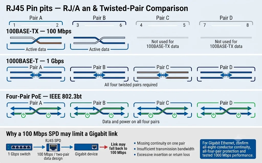
Dos pares de datos
100BASE-TX normalmente transmite datos a través de pares en los pines 1–2 y 3–6. Un protector diseñado solo alrededor de este arreglo no debe asumirse como compatible con Ethernet Gigabit.
Todos los cuatro pares
1000BASE-T utiliza todos los cuatro pares trenzados. Cualquier par faltante, mal dirigido o mal balanceado puede prevenir un enlace Gigabit o crear una operación inestable.
Demandas más altas de integridad de señal
A frecuencias más altas, la capacitancia parásita, la discontinuidad de impedancia, la pérdida de retorno y la diafonía se vuelven más críticas. Use solo un SPD específicamente validado.
Los protectores contra sobretensiones RJ45 PoE y no PoE no son intercambiables
Un modelo no PoE puede proteger solo circuitos de datos de bajo voltaje. Un modelo PoE debe mantener la transmisión de Ethernet mientras transporta energía continua de CC a través de los pares de conductores requeridos.
| Tipo de PoE | Designación IEEE | Potencia máxima de la fuente | Uso típico de pares | Lo que debe confirmar el comprador de SPD |
|---|---|---|---|---|
| PoE Tipo 1 | IEEE 802.3af | Hasta 15.4W | Normalmente dos pares alimentados | Modo PoE, voltaje, corriente, asignación de pares y tasa de datos. |
| PoE+ Tipo 2 | IEEE 802.3at | Hasta 30W | Normalmente dos pares alimentados | Corriente continua, calentamiento del conector, resistencia y caída de tensión. |
| PoE++ Tipo 3 | IEEE 802.3bt | Hasta 60W | Dos o cuatro pares alimentados según la implementación | Compatibilidad explícita con Tipo 3 y la disposición real de los pares alimentados. |
| PoE++ Tipo 4 | IEEE 802.3bt | Hasta 90W | Cuatro pares alimentados | Alimentación por cuatro pares, corriente por par, aumento de temperatura y caída de tensión. |
| PoE Pasivo | Específico del proveedor | Depende del sistema | Polaridad fija y asignación de pines | Voltaje CC exacto, polaridad, mapa de pines, corriente y compatibilidad del dispositivo. |
Para sistemas IEEE PoE
- Confirme 802.3af, 802.3at o 802.3bt.
- Confirme la compatibilidad con Mode A, Mode B y cuatro pares.
- Verifique el voltaje y la corriente máximos continuos.
- Verifique la resistencia CC y la caída de tensión esperada.
- Verifique la velocidad de datos por separado de la especificación PoE.
Para sistemas PoE pasivos
- Registre el voltaje exacto inyectado.
- Registre las asignaciones de pines positivo y negativo.
- Confirme la corriente máxima de carga.
- No asuma una negociación automática de PoE.
- Solicite aprobación por escrito para el cableado exacto.
Un cable RJ45 apantallado no reemplaza la conexión a tierra del SPD
La pantalla del cable, la carcasa metálica del RJ45 y el terminal PE del SPD tienen funciones relacionadas pero distintas. Deben coordinarse con el sistema local de equipotencialidad del sitio.
Controla el acoplamiento electromagnético
La pantalla ayuda a gestionar la interferencia electromagnética cuando está correctamente terminada y unida de acuerdo con el cableado estructurado y el diseño EMC.
Mantiene la continuidad de la pantalla
Una toma apantallada puede conducir la pantalla del cable a través del protector, pero la continuidad de la pantalla debe confirmarse en lugar de darse por sentada.
Desvía la corriente de sobretensión
El SPD necesita una conexión corta y de baja impedancia al sistema equipotencial local. Un conductor PE largo añade tensión inductiva.
Recomendado
- Una el SPD al mismo sistema PE local que el equipo protegido.
- Mantenga la conexión a tierra corta y directa.
- Confirme la continuidad de la pantalla cuando se utilice cableado apantallado.
- Separe los cables protegidos de los cables expuestos entrantes.
- Siga el diseño de compatibilidad electromagnética (EMC) y conexión equipotencial del proyecto.
Evitar
- Utilizar el blindaje del cable como única ruta de descarga.
- Conectar el SPD a una varilla de puesta a tierra aislada y remota que no esté relacionada con el sistema de protección de tierra (PE) local.
- Utilizar un conductor de tierra innecesariamente largo o indirecto.
- Tendido conjunto de cables protegidos y no protegidos.
- Asumir que todas las envolventes metálicas tienen la misma conexión equipotencial interna.
¿Debería instalarse el SPD RJ45 en el dispositivo, el switch o el armario?
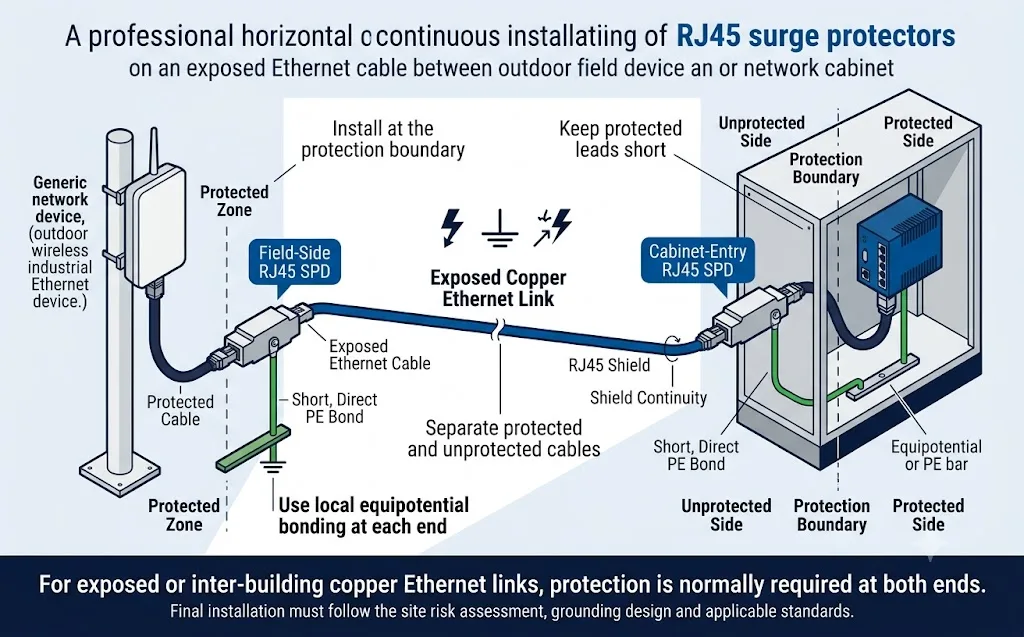
Instálelo donde el cable expuesto cruce hacia la zona protegida y lo más cerca posible de la entrada del equipo o gabinete que se está protegiendo.
| Escenario de instalación | Posición de protección recomendada | Razón |
|---|---|---|
| Cable exterior que entra en un edificio | En el límite de entrada del cable antes de que este se dirija a través de la zona protegida del edificio. | Reduce la energía de sobretensión que se transmite al cableado de red interno. |
| Ethernet de cobre entre edificios | En ambos puntos de entrada del edificio, conectados al sistema equipotencial local de cada edificio. | Ambos extremos pueden experimentar condiciones diferentes de sobretensión y potencial de tierra. |
| Dispositivo de red para exteriores o azoteas. | Cerca del dispositivo de campo y nuevamente en la entrada del edificio o gabinete. | Protege equipos sensibles en ambos extremos de la ruta expuesta. |
| Gabinete de control industrial | En la entrada de cables del armario antes de que la línea llegue al PLC, HMI, controlador o switch. | Mantiene el lado de la sobretensión entrante separado de los componentes electrónicos sensibles. |
| Rack de red multipuerto | Cerca del panel de conexión o switch utilizando un rack organizado o protección multicanal. | Proporciona protección centralizada y una ruta de conexión a tierra diseñada. |
| Enlace de red interno corto | Utilice una evaluación de riesgos del proyecto en lugar de instalar la protección automáticamente. | El riesgo puede ser menor cuando el enlace completo permanece dentro de una zona de protección conectada. |
Cómo evitar la pérdida de velocidad de red y la interferencia en la señal
Que un enlace se conecte no garantiza una compatibilidad total. Puede conectarse a una velocidad inferior, acumular errores CRC o volverse inestable durante el tráfico real y la carga PoE.
| Síntoma observado | Posible causa relacionada con el SPD | Verificación recomendada |
|---|---|---|
| El enlace de 1 Gbps cae a 100 Mbps | Solo dos pares tienen continuidad o el protector está diseñado para 100 Mbps. | Verifique los ocho conductores, el mapa de pares y la tasa de transferencia de datos máxima documentada. |
| El enlace se desconecta repetidamente | Pérdida excesiva, discontinuidad de impedancia, contactos deficientes o perturbaciones en la conexión a tierra. | Inspeccione los conectores, los cables de conexión, los registros del switch y los resultados de las pruebas de canal. |
| Aumento de errores de CRC o de paquetes | Pérdida de retorno, diafonía, desequilibrio de pares o atenuación de alta frecuencia. | Compare los contadores de errores antes y después de la instalación y certifique el canal completo. |
| El dispositivo PoE se reinicia bajo carga | Resistencia de CC excesiva, caída de tensión, calor o corriente de carga insuficiente. | Mida la tensión en el dispositivo alimentado y verifique la capacidad de corriente continua del SPD. |
| Solo algunos dispositivos PoE funcionan | Soporte de modo A/B incorrecto, cableado PoE pasivo o continuidad incompleta del par alimentado. | Confirme el PSE, el PD, la asignación de pines y el diagrama de pares del protector. |
| Aparece ruido después de la instalación | Terminación de blindaje deficiente, problemas de conexión a tierra o acoplamiento entre cables protegidos y no protegidos. | Revise la continuidad del blindaje, la ruta de PE y la separación física de los cables. |
Registrar una línea base
- Velocidad de enlace negociada.
- Estado de voltaje y potencia PoE.
- Contadores de errores y CRC del puerto del switch.
- Resultado de la certificación del cable existente.
Repita las mismas comprobaciones
- Confirme la misma velocidad negociada.
- Compruebe si existen errores de paquete o CRC nuevos.
- Pruebe el dispositivo bajo la carga máxima de PoE.
- Certifique el canal completado cuando sea necesario.
No realice pruebas únicamente de continuidad.
- La continuidad no garantiza el ancho de banda.
- Un ping exitoso no confirma el margen de señal.
- La velocidad de enlace por sí sola no revela errores intermitentes.
- Utilice equipos de prueba de red y cableado adecuados.
No compares los SPDs RJ45 solo por un encabezado de “5kV” o “10kV”
Un valor de sobretensión sin la forma de onda, las condiciones de la fuente, la corriente, la combinación de conductores y la tensión limitante medida no es suficiente para una comparación técnica.
| Parámetro | Lo que le indica al comprador | Lo que debe ser confirmado |
|---|---|---|
| Un | Tensión nominal de funcionamiento del circuito protegido. | Indica si el valor se aplica a conductores de datos, alimentación PoE o ambos. |
| Uc / MCOV | Tensión máxima de funcionamiento continuo que el SPD puede tolerar. | Valores de línea a línea, par a par y línea a tierra cuando corresponda. |
| Voltaje de limitación / superior | Voltaje remanente en el lado protegido durante una prueba de sobretensión definida. | Forma de onda de prueba, nivel de corriente, combinación de conductores y modo de protección. |
| Corriente de impulso / In | Rendimiento de corriente de sobretensión bajo una forma de onda de corriente declarada. | Si el valor se aplica por conductor, par, canal o dispositivo completo. |
| Prueba de impulso de rayo / D1 | Rendimiento de impulso de mayor energía cuando se declara para SPD de línea de señal. | Categoría de prueba, forma de onda, rutas de conducción y modelo exacto probado. |
| Pérdida de inserción | Atenuación de señal introducida por el protector. | El rango de frecuencia en el que se midió el valor. |
| Pérdida de retorno | Qué tan bien mantiene la ruta de la señal la impedancia característica requerida. | Frecuencia de prueba, categoría de canal y límite de prueba aplicable. |
| Pares y modos protegidos | Qué conductores y combinaciones de conductores reciben protección. | Par a par, conductor a tierra, blindaje a tierra y todos los pines requeridos. |
| Norma aplicable | El marco de prueba y clasificación utilizado para el producto. | Edición estándar, número de informe, modelo probado y alcance del informe. |
Marco normativo IEC pertinente
La norma IEC 61643-21 cubre los dispositivos de protección contra sobretensiones (SPD) conectados a redes de telecomunicaciones y señalización, incluidas las redes que suministran energía en la misma línea, como PoE.
La norma IEC 61643-22 establece los principios de selección, ubicación, funcionamiento y coordinación para los dispositivos de protección contra sobretensiones (SPD) en sistemas de telecomunicaciones y señalización.
Documentos a solicitar
- Hoja de datos del modelo específico.
- Informe de pruebas conforme a la norma IEC o al proyecto correspondiente.
- Diagrama de pines RJ45 y canal de protección.
- Datos de prueba de transmisión o de canal completo.
- Datos de corriente, resistencia y temperatura PoE.
- Instrucciones de instalación y puesta a tierra.
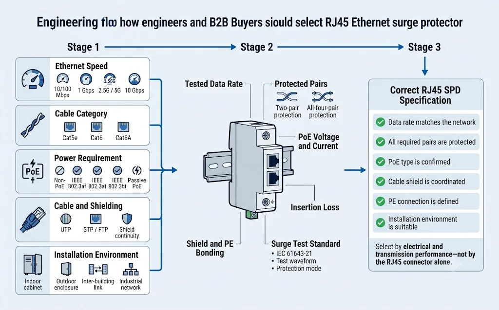
Flujo de selección de protectores contra sobretensiones RJ45 para ingenieros y compradores
Complete estas seis comprobaciones antes de solicitar una muestra, aprobar un modelo de sustitución o comparar presupuestos de fabricantes de equipos originales (OEM).
Identifique la velocidad real del enlace.
Lea las especificaciones del switch y del dispositivo conectado. No deduzca la velocidad requerida únicamente a partir de la etiqueta del cable.
Confirme si se trata de PoE o no PoE.
Registre el tipo de IEEE PoE o el voltaje exacto de PoE pasivo, la polaridad y la corriente de carga.
Mapee los pares de conductores.
Confirme qué pares transportan datos y energía, y qué conductores están protegidos por el SPD.
Defina el entorno.
Especifique el gabinete interior, la caja exterior, el dispositivo de techo, la ruta entre edificios o la red industrial.
Defina la conexión a tierra y el montaje.
Confirme la instalación en línea, en pared, en rack o en gabinete, así como el método local de PE o de conexión equipotencial.
Revise el rendimiento documentado.
Compare los datos de transmisión del modelo exacto, Uc, la tensión límite, la forma de onda de sobretensión y el informe de prueba.
¿Qué configuración actual de RJ45 LEEYEE se adapta a la aplicación?
La siguiente matriz se limita a las configuraciones documentadas en la información pública de productos y los datos de catálogo actuales de LEEYEE. No implica capacidad Gigabit, 10G o PoE++.
LY21-2 CAT1 / CAT4 / CAT8
Protección de señal de red RJ45 para líneas de datos Ethernet sin PoE.
- Tipo de red
- Ethernet sin PoE
- Tasa máxima
- 100 Mbps
- Tensión de funcionamiento
- 5V CC
- Uc máxima
- 6V CC
- Corriente de carga
- 500 mA
- Pérdida de inserción
- ≤0,2dB
- Grado de protección
- IP20
CAT1, CAT4 y CAT8 son etiquetas de configuración de producto. No deben interpretarse como rendimiento de cableado Ethernet Cat1, Cat4 o Cat8.
Ver producto sin PoELY21-2 PoE
Protección combinada para circuitos de alimentación PoE y datos Ethernet.
- Tipo de red
- Alimentación PoE + datos Ethernet
- Tasa máxima
- 100 Mbps
- Uc de alimentación PoE
- Hasta 60V CC
- Corriente de carga
- 500 mA
- Voltaje de funcionamiento de los datos
- 5V CC
- Pérdida de inserción
- ≤0,2dB
- Grado de protección
- IP20
Confirme el voltaje PoE, el modo de par alimentado, la corriente continua y la configuración exacta de los pines antes de realizar el pedido. No describa este modelo como compatible con Gigabit o PoE++.
Confirmar configuración PoELY21-2 CAT16 / CAT24
Protección RJ45 multipuerto para armarios de red centralizados sin PoE.
- Opciones de puerto
- 16 puertos / 24 puertos
- Tipo de red
- Ethernet sin PoE
- Tasa máxima
- 100 Mbps
- Tensión de funcionamiento
- 5V CC
- Uc máxima
- 6V CC
- Pérdida de inserción
- ≤0,2dB
- Grado de protección
- IP20
CAT16 y CAT24 identifican el número de puertos protegidos. No describen el rendimiento de los cables Cat6, Cat6A o Cat8.
Solicitar detalles de puertos múltiplesLímite de aplicación actual
Las configuraciones públicas de LEEYEE mostradas anteriormente tienen una tasa de transmisión máxima documentada de 100 Mbps. No deben promocionarse para las siguientes aplicaciones a menos que se confirme un modelo probado por separado y un informe técnico de respaldo:
- Ethernet Gigabit 1000BASE-T.
- 2.5GBASE-T or 5GBASE-T.
- Canales Cat6A o 10GBASE-T.
- IEEE 802.3bt PoE++ o PoE de alta potencia de cuatro pares.
La página explica cómo los compradores deben evaluar esos requisitos de mayor rendimiento, pero no afirma que la gama actual LY21-2 los admita.
Información para confirmar antes de un pedido de muestra o por volumen de SPD RJ45
Una consulta completa ayuda al proveedor a seleccionar el circuito de protección correcto en lugar de cotizar un modelo visualmente similar pero eléctricamente incompatible.
Detalles de transmisión
- 10/100Mbps, 1Gbps, 2.5G, 5G o 10G.
- Cableado Cat5e, Cat6 o Cat6A.
- Cable blindado o sin blindar.
- Longitud máxima del cable.
- Número de puertos requeridos.
Requisitos de alimentación
- Estándar PoE o no PoE.
- Voltaje y corriente máxima de PoE.
- Modo A, Modo B o alimentación por cuatro pares.
- Polaridad PoE pasiva cuando corresponda.
- Límite de caída de tensión permitido.
Mecánico y ambiental
- Montaje en línea, en pared, en gabinete o en rack.
- Carcasa para interiores o ubicación en exteriores.
- Grado de protección IP requerido.
- Temperatura de funcionamiento.
- Método de conexión a tierra de PE, blindaje y gabinete.
Rendimiento contra sobretensiones
- Norma IEC o de proyecto aplicable.
- Forma de onda y categoría de prueba requeridas.
- Modos de protección y pines protegidos.
- Requisitos de Uc y tensión limitadora.
- Informes de prueba requeridos.
Información del pedido
- Muestra y volumen anual.
- Mercado objetivo y necesidades de certificación.
- Marca privada o marca LEEYEE.
- Idioma del embalaje y la etiqueta.
- Calendario de entrega requerido.
Requisitos de validación
- Aprobación de la muestra de preproducción.
- Verificación de la velocidad de red.
- Prueba de carga PoE.
- Revisión del informe de pruebas de sobretensión.
- Plan de inspección y trazabilidad de lotes.
Plantilla de consulta para SPD RJ45 copiable
Envíe esta información junto con el diagrama de red o la especificación del proyecto.
Aplicación:
Equipo protegido:
Velocidad de red:
Categoría de cable:
Cable blindado o no blindado:
PoE o no PoE:
Estándar PoE o voltaje PoE pasivo:
Potencia y corriente PoE máximas:
Pares alimentados y asignación de pines:
Pares protegidos requeridos:
Número de puertos:
Longitud máxima del cable:
Instalación en interiores o exteriores:
Método de montaje:
Grado de protección IP requerido:
Método de conexión a tierra y enlace:
Estándar de sobretensión requerido:
Uc requerido, voltaje de limitación y nivel de prueba de sobretensión:
Certificados o informes de prueba requeridos:
Cantidad de muestra:
Cantidad anual estimada:
Requisitos de logotipo, etiqueta y embalaje OEM:
Mercado objetivo:
Seis errores que conducen a un pedido incorrecto de SPD RJ45
Pedido solo por conector
El conector RJ45 encaja, pero el circuito de protección interno podría admitir un voltaje, mapa de pares o velocidad de datos incorrectos.
Uso de Cat6 como prueba de Gigabit
Una etiqueta de categoría de cable o un conector metálico no sustituyen los datos de transmisión probados.
Ignorar la corriente PoE
Un protector puede transmitir datos pero sobrecalentarse, generar una caída de tensión o reiniciar el dispositivo alimentado bajo carga.
Comparar solo los kV de sobretensión
La cifra está incompleta sin la forma de onda, la corriente, el modo de prueba y la tensión de limitación medida.
Instalación sin conexión equipotencial
Un SPD seleccionado correctamente no puede funcionar según lo previsto sin una ruta de descarga local corta.
Omitir la validación del enlace
La red puede parecer conectada mientras opera a una velocidad menor o acumula errores de comunicación.
Continúa el camino de selección de red y de señal SPD
Preguntas frecuentes sobre el protector contra sobretensiones RJ45
¿Se puede utilizar el mismo protector contra sobretensiones RJ45 para Cat5e y Cat6?
Solo cuando el SPD haya sido probado para la velocidad de red y la frecuencia de transmisión requeridas. La interfaz RJ45 puede encajar físicamente en ambos sistemas de cableado, aunque el circuito interno limite el canal resultante.
¿Un protector contra sobretensiones RJ45 reduce la velocidad de la red?
Un SPD seleccionado e instalado correctamente debe mantener su rendimiento de transmisión declarado. Un producto inadecuado puede provocar que un enlace negocie una reducción de 1 Gbps a 100 Mbps, aumentar los errores de paquetes o causar desconexiones intermitentes.
¿Se puede utilizar un SPD RJ45 de 100Mbps en una red Gigabit?
No. Un producto con una tasa máxima documentada de 100 Mbps no debe especificarse para 1000BASE-T. Gigabit Ethernet requiere los cuatro pares trenzados y un rendimiento de transmisión de alta frecuencia adecuado.
¿Se puede instalar un protector contra sobretensiones RJ45 que no es PoE en un cable PoE?
No, a menos que el fabricante confirme explícitamente el voltaje PoE, la corriente de carga y la configuración de los pares alimentados. Es posible que un protector de línea de datos sin capacidad PoE no soporte de forma segura la alimentación PoE continua.
¿El cable Ethernet apantallado elimina la necesidad de conexión a tierra?
No. El blindaje del cable ayuda a gestionar las interferencias electromagnéticas, pero no sustituye automáticamente la conexión corta del SPD a la toma de tierra (PE) local o al sistema de conexión equipotencial.
¿Debería instalarse un protector contra sobretensiones de Ethernet en ambos extremos?
La protección en ambos extremos es generalmente adecuada para enlaces Ethernet de cobre en exteriores, azoteas o entre edificios. Cada SPD debe instalarse en el límite de protección local y conectarse al sistema equipotencial local.
¿Qué es más importante: la pérdida por inserción o la capacidad de corriente de sobretensión?
Ambos son importantes. Los parámetros de transmisión determinan si la red permanece estable, mientras que los parámetros de sobretensión determinan la capacidad de protección. Un producto que solo funciona bien en un área no constituye una solución completa.
¿Cómo puede un comprador verificar la declaración de 10kV de un proveedor?
Solicite el informe de prueba y confirme la forma de onda de voltaje, la corriente asociada, las condiciones de la fuente, las combinaciones de conductores protegidos, los modos de protección y el voltaje límite medido.
¿El LEEYEE LY21-2 admite actualmente Gigabit Ethernet?
Las configuraciones LY21-2 publicadas actualmente indican una tasa de transmisión máxima de 100Mbps. No deben describirse como compatibles con Gigabit a menos que se confirme formalmente un modelo Gigabit probado por separado.
¿Qué información debe enviarse a LEEYEE para la selección del modelo?
Envíe la velocidad de Ethernet, la categoría del cable, el tipo de PoE, el voltaje, la corriente, la asignación de pares, el número de puertos, la longitud del cable, el entorno de instalación, el método de conexión a tierra, la norma requerida y la cantidad del pedido.
Normas y fuentes técnicas
La selección final del proyecto debe verificarse con las especificaciones exactas del equipo, las normas vigentes, las reglas de instalación locales y los documentos técnicos específicos del modelo del proveedor.
- IEC 61643-21:2025, Dispositivos de protección contra sobretensiones conectados a redes de telecomunicaciones y señalización: requisitos de rendimiento y métodos de ensayo. Página de publicación IEC .
- IEC 61643-22:2015, Dispositivos de protección contra sobretensiones conectados a redes de telecomunicaciones y señalización: principios de selección y aplicación. Página de publicación IEC .
- Fluke Networks, Explicación de las categorías de cables Ethernet, incluyendo las frecuencias de referencia para el cableado Cat5e, Cat6 y Cat6A. Artículo de Fluke Networks .
- Fluke Networks, Pérdida de retorno: causas y procedimientos de prueba. Artículo de Fluke Networks .
- Cisco, Fundamentos del cableado Ethernet en una red de datos empresarial, incluyendo la diferencia en el uso de conductores entre 100BASE-TX y 1000BASE-T. Cisco Learning Network .
- Cisco, Qué es Power over Ethernet, cubriendo el desarrollo de PoE según IEEE 802.3af, 802.3at y 802.3bt. Descripción general de PoE de Cisco .
- Datos de producto publicados para el protector contra sobretensiones de señal de red LEEYEE LY21-2 RJ45 100Mbps. Página del producto LEEYEE .
- Manual de selección de dispositivos de protección contra sobretensiones LEEYEE, que incluye las configuraciones documentadas LY21-2 PoE, CAT16/CAT24 y CAT1/CAT4/CAT8. Catálogo LEEYEE .
¿Necesitas un SPD RJ45 que se adapte exactamente a tu red?
Envíe la velocidad de Ethernet, la categoría del cable, el estándar PoE, el voltaje, la corriente, el mapa de pares, la posición de instalación, el método de conexión a tierra y el estándar de prueba requerido. LEEYEE puede revisar la aplicación antes de la confirmación de la muestra o del pedido OEM.
