
A proteção contra surtos Modbus geralmente significa proteger o circuito de comunicação RS485 utilizado pelo Modbus RTU. Instale um SPD de linha de sinal compatível onde um cabo RS485 exposto entra no PLC, gateway ou invólucro de dispositivo em campo. Para links externos ou inter-edifícios, avalie a proteção em ambas as extremidades. Modbus TCP usa um SPD Ethernet em vez de um SPD RS485.
O verdadeiro alvo de proteção é o transceiver RS485 dentro do PLC, RTU, medidor de energia, gateway ou instrumento de campo remoto—não simplesmente os dois condutores no cabo de comunicação.
Este guia explica onde a energia de surto entra em um sistema Modbus, onde os SPDs devem ser instalados, se a proteção pode afetar a comunicação e o que os compradores de projetos ou OEM devem confirmar antes de fazer o pedido.
Índice
Onde deve ser instalado um protetor contra surtos Modbus?
Identifique a interface condutora e o limite da zona de proteção antes de selecionar o SPD.
Modbus RTU e RS485 estão relacionados, mas não são a mesma coisa
Modbus define as mensagens trocadas por dispositivos industriais. RS485 define a interface elétrica utilizada para transmitir essas mensagens em uma linha serial equilibrada. Modbus TCP transporta a comunicação Modbus através de Ethernet e TCP/IP. [1] [2]
A palavra “Modbus” sozinha não é suficiente para a seleção do SPD. Primeiro identifique se o circuito condutor é RS485, Ethernet, alimentação auxiliar ou outra interface física.
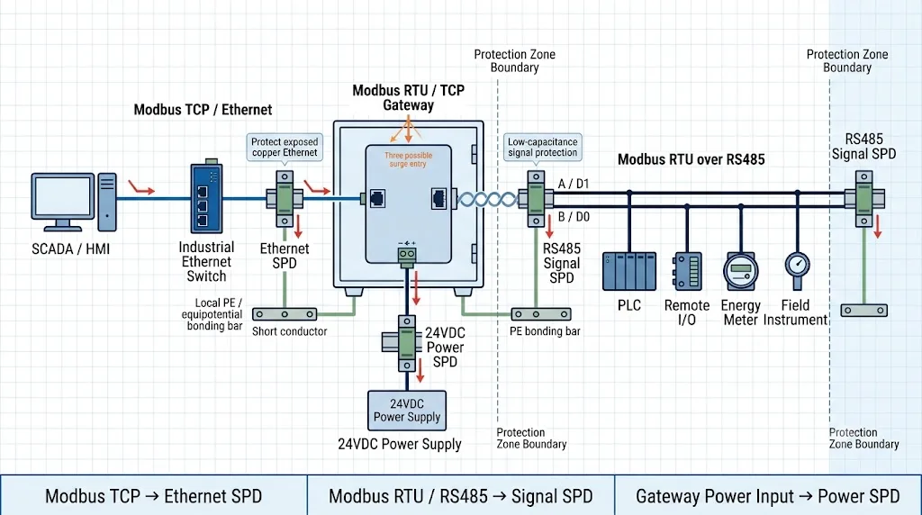
Por que linhas de comunicação Modbus RS485 longas estão expostas a surtos
A sinalização diferencial RS485 fornece uma imunidade útil ao ruído, mas não torna o transceptor imune a tensões induzidas por raios, transientes de comutação ou diferenças de potencial excessivas entre zonas de aterramento.
Rotas de cobre longas
Cabos de comunicação longos proporcionam um caminho de acoplamento maior para campos eletromagnéticos produzidos por raios e comutação.
Equipamento externo
Estações de bombeamento, medidores de energia, dispositivos de monitoramento solar e controladores de campo costumam usar rotas de cabos expostas.
Diferentes zonas de aterramento
Armários ou edifícios podem experimentar diferentes potenciais de terra locais durante eventos de raios ou falhas elétricas.
Motores e cargas de comutação
Contatores, motores, soldadores e instalações de VFD podem criar distúrbios ao redor de fiações de comunicação mal separadas.
Vários caminhos de cabos
Um PLC ou gateway pode ser conectado à energia AC, energia 24VDC, RS485, Ethernet e sinais de campo ao mesmo tempo.
Falha na porta de comunicação
Um transceptor RS485 danificado pode interromper a comunicação, mesmo quando a CPU do PLC e a fonte de alimentação ainda parecem operacionais.
A fiação de par trançado ajuda a controlar a interferência normal. A proteção contra surtos fornece um caminho controlado para a corrente transitória. O roteamento, aterramento, isolamento e terminação corretos ainda são necessários.
Onde deve ser instalado um SPD RS485 em uma rede Modbus RTU?
Instale o SPD onde um cabo de campo exposto entra no gabinete, envoltório, edifício ou zona de proteção contendo o equipamento sensível. O cabo de campo deve alcançar o SPD antes de ser roteado ao lado do PLC, gateway ou módulo de comunicação.
| Cenário de rede Modbus | Posição recomendada do SPD | Proteger ambas as extremidades? | Razão engenharia |
|---|---|---|---|
| Link curto dentro de um gabinete aterrada | Um SPD de linha externa separado pode não ser necessário após a avaliação de risco do local. | Geralmente não | O cabo é curto e permanece dentro de uma zona equipotencial. |
| Do gabinete do PLC para um instrumento remoto interno | Na entrada do cabo do gabinete do PLC e perto do equipamento remoto quando o trajeto cruza zonas expostas. | Frequentemente apropriado | A linha pode cruzar rotas longas, áreas de energia ou pontos de aterramento locais separados. |
| Medidor externo, estação de bomba ou RTU remoto | Na entrada do painel de controle principal e na entrada da estrutura remota. | Comumente sim | Ambas as extremidades estão conectadas a equipamentos expostos e sistemas de aterramento locais. |
| Cabo de cobre RS485 entre edifícios | Na entrada do cabo de cada edifício ou zona de proteção. | Sim | Diferenças de potencial de terra e exposição a raios podem afetar ambas as extremidades. |
| Gateway conectado a um tronco de campo | Na entrada do cabo RS485 exposto ao lado do gateway e na estrutura remota quando necessário. | Depende da exposição | O lado RS485 deve ser avaliado independentemente de Ethernet e alimentação. |
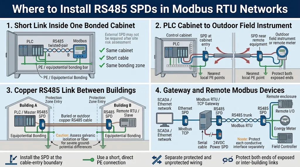
Quando o cabo de campo desprotegido atravessa o invólucro antes de chegar ao DPS, a energia de surto já entrou na área protegida e pode acoplar-se à fiação próxima.
Como devem passar através do SPD as linhas A/B ou D0/D1 do Modbus RTU?
O DPS de sinal RS485 é normalmente instalado em série. O cabo de campo exposto conecta-se ao lado LINE ou IN. A saída protegida conecta-se ao PLC, RTU, medidor, gateway ou controlador de campo.
Na convenção oficial de nomenclatura de linha serial Modbus, D1 corresponde a B/B′ e D0 corresponde a A/A′. Os fabricantes de equipamentos nem sempre usam A e B de forma consistente, portanto verifique o manual de cada dispositivo e mantenha a continuidade dos condutores através do DPS. [1]
Conecte os condutores RS485 de entrada expostos aos terminais marcados LINE, FIELD ou IN de acordo com o diagrama do DPS.
Conecte os terminais protegidos OUT ou EQUIPMENT à porta de comunicação usando a fiação mais curta possível.
Proteja o par balanceado D0/D1 e confirme como o condutor Common da rede é tratado no projeto completo do sistema.
Confirme se o SPD ou a combinação de SPDs fornece canais suficientes para os pares de transmissão e recepção.
O SPD não substitui a terminação de linha nem os resistores de polarização da rede.
Para a fiação terminal a terminal, a seleção entre dois fios e quatro fios e os parâmetros detalhados do sinal, consulte o Guia de fiação e seleção de SPD RS485.
O manto do cabo, o comum do sinal e o PE do SPD não são o mesmo condutor
Cada conexão tem uma função diferente. Combiná-las sem um projeto de sistema pode causar falhas de comunicação ou um caminho de descarga de surto ineficaz.
Blindagem do cabo
A blindagem ajuda a controlar o acoplamento eletromagnético ao redor do par de comunicação. Seu esquema de aterramento deve seguir o projeto EMC do equipamento e do projeto.
Comum de sinal
Common fornece o condutor de referência associado ao par balanceado RS485. Ele não é automaticamente o mesmo que PE ou a blindagem do cabo.
Condutor PE ou de ligação do SPD
Este é o caminho pretendido para desvio da corrente de surto até o sistema local de equipotencialização. Mantenha-o curto e direto.
O guia da linha serial Modbus descreve o cabo blindado e a conexão do terra de proteção em uma extremidade como sua base. A ligação final ainda depende do gabinete, do edifício, do método de isolamento, do ambiente EMC e das instruções do equipamento. [1]
Um SPD limita sobretensão transitória. O isolamento galvânico ajuda a lidar com a corrente causada por diferenças contínuas ou temporárias de potencial de terra. Ligações expostas entre edifícios podem exigir ambos, ou conversão para fibra.
Um protetor contra surtos RS485 afetará a comunicação Modbus?
Um SPD de sinal corretamente selecionado não deve perturbar de forma significativa o enlace Modbus RTU pretendido. Um dispositivo incompatível pode adicionar capacitância, resistência em série ou perda de inserção e reduzir a margem de sinal de uma rede já fraca.
| Parâmetro | Por que isso importa | Possível sintoma | Confirmação do comprador |
|---|---|---|---|
| Tensão máxima de funcionamento contínuo | O SPD deve permanecer inativo durante a maior tensão normal presente no circuito. | Fuga de corrente, distorção, aquecimento ou envelhecimento prematuro | Confirme a tensão real em cada condutor protegido. |
| Nível de proteção da tensão | A tensão residual deve ser coordenada com a porta de comunicação protegida. | O SPD sobrevive, mas o transceptor ainda é danificado. | Solicitar o modo de teste, forma de onda, corrente e valor. |
| Capacitância da linha | Uma capacitância excessiva pode atrasar as transições de sinal e reduzir a margem de transmissão. | Erros CRC, tempos limite ou instabilidade a taxas de baud mais elevadas | Solicitar dados de capacitância sob condições definidas. |
| Resistência e perda de inserção | A impedância adicionada pode atenuar o sinal diferencial. | Alcance reduzido, nós remotos instáveis ou velocidade útil inferior | Confirmar resistência, perda de inserção e taxa de dados. |
| Contagem de canais protegidos | Sistemas de dois e quatro fios requerem disposições de canais diferentes. | Cablagem incorreta ou condutores desprotegidos | Enviar o esquema de terminais antes da confirmação do modelo. |
| conexão PE | Um condutor de ligação longo ou indireto aumenta a tensão transitória instalada. | Falha repetida na porta de comunicação após sobretensões | Confirmar a barra PE local e a posição de montagem. |
A tensão de alimentação do painel de controlo não equivale automaticamente à tensão presente nos condutores de comunicação RS485. Confirme o circuito protegido real e selecione a proteção de energia e sinal separadamente.
Sintoma provavelmente relacionado com sobretensão
A porta de comunicação falha após uma tempestade, o mesmo nó remoto requer substituição repetidamente ou vários dispositivos falham no mesmo limite de cabo.
Sintoma provavelmente relacionado com a integridade do sinal
Os erros começam imediatamente após a instalação, agravam-se a taxas de baud mais elevadas ou afetam dispositivos perto do fim de um tronco longo.
Modbus TCP requer proteção Ethernet, não um SPD RS485
A comunicação Modbus TCP é transmitida através de Ethernet TCP/IP. Um SPD RS485 de dois fios não pode proteger uma ligação Ethernet RJ45. O SPD Ethernet deve corresponder à velocidade da rede, conetor, categoria de cabo, blindagem e qualquer energia transportada no cabo. [2]
Lado RS485
Use um SPD de linha de sinal adequado para o circuito Modbus RTU, tensão e condições de instalação.
Lado Ethernet
Use um SPD Ethernet ou RJ45 adaptado à velocidade, cabo, blindagem e requisitos PoE.
Entrada de energia do gateway
Avalie a fonte de alimentação 24VDC ou AC de forma independente e utilize o SPD de energia correspondente, quando necessário.
A norma IEC 61643-21:2025 abrange SPDs para redes de telecomunicações e sinalização, incluindo redes que também podem fornecer energia na mesma linha, como o PoE. [3]
Lista de verificação para seleção de protetores contra surtos Modbus para compradores B2B
Um fornecedor não pode selecionar o SPD correto apenas com base em "Modbus" ou "RS485". Forneça a interface física, limites elétricos, rota do cabo, condições de ligação à terra e dados de teste necessários antes de aprovar um modelo.
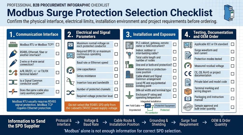
Peça ao fornecedor para identificar a forma de onda de teste, modo de acoplamento, modo de proteção e condições de medição da tensão residual. A norma IEC 61643-21 especifica requisitos e métodos de teste para SPDs utilizados em redes de telecomunicações e sinalização. [3]
Protetor contra surtos de sinal de dados RS485 LY10
O LY10 é um SPD de sinal para calha DIN para RS485, telemetria, PLC, sensores e circuitos de comunicação industrial. É instalado em série antes do equipamento protegido.
Trate o LY10 como um modelo candidato em vez de o selecionar apenas pela palavra "Modbus". Confirme a tensão do circuito, disposição dos condutores, velocidade de dados, rota do cabo e condições de ligação à terra antes de encomendar.
Um armário descrito como "sistema de 24V" não requer automaticamente um SPD RS485 de 24V. Confirme a tensão mais elevada presente nos condutores reais encaminhados através do SPD de sinal.
Seis erros comuns na proteção contra surtos Modbus
Os cabos RS485, Ethernet e de campo remoto permanecem como caminhos condutores separados para a entrada de sobretensões.
A tensão de alimentação do armário não define automaticamente a tensão do circuito de comunicação.
Ligações exteriores ou entre edifícios requerem frequentemente proteção em ambas as entradas da zona de proteção.
A Ethernet requer proteção adaptada ao seu conector, pares de cabos e desempenho de transmissão.
Um condutor de ligação longo, enrolado ou indireto aumenta a tensão residual instalada.
Condutores invertidos, terminação deficiente, ramais longos e topologia errada podem tornar a rede instável.
Perguntas frequentes sobre proteção contra surtos Modbus
Toda rede Modbus RTU precisa de um SPD RS485?
Não. Uma ligação interna curta dentro de um armário ligado à terra tem um risco diferente de um cabo longo exterior ou entre edifícios. Avalie a exposição, zonas de ligação à terra, valor do equipamento e disponibilidade necessária.
O cabo Modbus RS485 deve ser protegido em ambas as extremidades?
A proteção em ambas as extremidades é geralmente avaliada para ligações exteriores, de longa distância, entre edifícios ou zonas de ligação à terra separadas. Um cabo interno curto pode não necessitar de dois SPDs.
Pode um SPD RS485 causar erros CRC ou timeouts?
Um SPD inadequado pode contribuir para erros através de capacitância excessiva, resistência, perda de inserção ou cablagem incorreta. Verifique também a polaridade, terminação, ramais e topologia.
D1 é o mesmo que A ou B?
O guia oficial de linha série Modbus mapeia D1 para B/B′ e D0 para A/A′. Alguns fabricantes utilizam as etiquetas A/B de forma diferente, pelo que deve verificar os manuais de ambos os equipamentos.
Pode um SPD de alimentação de 24VDC proteger uma linha RS485?
Não automaticamente. Os SPDs de potência e os SPDs de sinal têm requisitos diferentes de tensão, corrente, capacitância, transmissão e terminais.
Que protetor deve ser utilizado para Modbus TCP?
Utilize um SPD de linha de dados Ethernet compatível com a velocidade da rede, conector, categoria de cabo, blindagem e quaisquer requisitos de PoE.
Um SPD RS485 substitui o resistor de terminação?
Não. O SPD limita a sobretensão transitória. Os componentes de terminação e polarização gerem a integridade do sinal e as condições de repouso do barramento.
Que informações devem ser enviadas antes de encomendar?
Envie a interface, esquema de cablagem, diagrama de terminais, tensão do circuito, taxa de transmissão (baud rate), comprimento do cabo, número de nós, posição de instalação, método de ligação à terra, requisitos de teste e detalhes da encomenda OEM.
Continue com seleção em nível de interface e gabinete
Normas e fontes primárias
A seleção final deve ser verificada de acordo com a especificação mais recente do projeto, manual do equipamento, ficha técnica do produto aprovada e requisitos locais aplicáveis.
- Organização Modbus, Especificação e Guia de Implementação do MODBUS sobre Linha Série V1.02. Abrange interfaces de dois e quatro fios, nomenclatura D0/D1, terminação, polarização, blindagem e cablagem.
- Organização Modbus, Guia de Implementação de Mensagens MODBUS sobre TCP/IP V1.0b. Descreve o envio de mensagens Modbus sobre Ethernet TCP/IP e implementação de gateway.
- Comissão Eletrotécnica Internacional, IEC 61643-21:2025. Requisitos e métodos de teste para SPDs ligados a redes de telecomunicações e sinalização.
- Comissão Eletrotécnica Internacional, IEC 61643-22:2015. Princípios de seleção, operação, localização e coordenação para SPDs de redes de sinalização.
- LEEYEE, Dispositivo de Proteção contra Surtos para Sinal de Dados LY10. Parâmetros do produto publicados atualmente e informações de instalação.
Envie o caminho completo de comunicação Modbus—não apenas “RS485”
Forneça o modelo do dispositivo, diagrama de terminais, tensão real do circuito, taxa de transmissão, comprimento do cabo, número de nós, posições de instalação, esquema de ligação à terra, dados de teste necessários e quantidade prevista da encomenda. A LEEYEE pode ajudar a identificar quais as interfaces que requerem proteção RS485, Ethernet ou do lado da alimentação.
