
Um SPD de Gap de Faísca N-PE é o caminho de proteção contra surtos dedicado instalado entre o neutro e a terra de proteção em muitas configurações 3+1 e 1+1. Também pode ser descrito como um dispositivo de proteção contra surto N-PE, atenuador de corrente de raio N-PE ou módulo de proteção de gap de faísca N-PE.
Para construtores de painéis e compradores de OEM, a pergunta importante não é apenas o que é o componente. Você precisa saber por que ele é usado em sistemas TT, como ele difere de um módulo MOV comum e quais dados específicos do caminho devem ser verificados antes de aprovar o SPD completo.
Índice
Resposta Rápida: O que é um SPD de Gap de Faísca N-PE?
Um SPD de gaveta de centelha N-PE é um elemento de comutação de tensão conectado entre o neutro e a terra de proteção. Durante a operação normal, ele permanece em um estado de alta impedância. Durante uma sobretensão, ele comuta para condução e fornece um caminho de descarga do N para o PE.
Em um SPD típico trifásico 3+1, três caminhos limitadores de tensão protegem L1-N, L2-N e L3-N. O quarto caminho protege N-PE. Paratécnicos N-PE baseados em gaveta de centelha são utilizados em configurações documentadas 3+1 e 1+1 para sistemas TT e TN selecionados, sujeitos ao projeto de instalação e instruções do fabricante.[3][5]
| Caminho de proteção | Função típica | Principais verificações do comprador |
|---|---|---|
| L1-N, L2-N, L3-N | Limitar a tensão de sobretensão fase-a-neutro | Uc, Up, In, Imax ou Iimp |
| N-PE | Fornecer o caminho comum de descarga de neutro para terra | Uc, Up, TOV, corrente de seguimento, In ou Iimp |
Significado do comprador: nunca aprovar um “SPD 4P” apenas pela contagem de polos. Confirmar se o circuito interno é 3+1 ou 4+0 e verificar o caminho N-PE separadamente.
O que significa Proteção N-PE?
N significa neutro. PE significa terra de proteção. A proteção N-PE significa que o SPD inclui um caminho de proteção contra surto definido entre esses dois condutores.
O caminho N-PE não se destina a conduzir a corrente de carga normal. Seu propósito é controlar a tensão excessiva entre o neutro e a terra durante um evento transitório.
Em uma configuração 3+1, a corrente de sobretensão dos condutores de fase é inicialmente tratada pelos três caminhos L-N. O elemento N-PE então fornece a rota de descarga compartilhada em direção à terra de proteção.
Por que SPDs 3+1 são comuns em sistemas TT?
Em um sistema TT, o aterramento protetivo da instalação está conectado a um sistema de aterramento local. O neutro está conectado ao ponto de aterramento da fonte. N e PE permanecem separados dentro da instalação.
Uma configuração 3+1 permite que os três caminhos de proteção fase-neutro trabalhem juntos com um caminho neutro-terra dedicado. A IEC 61643-12 fornece princípios para seleção, localização e coordenação de DPSs AC, enquanto a IEC 60364-5-53 abrange a seleção e instalação de dispositivos utilizados em instalações de baixa tensão.[3][4]
Documentação oficial do fabricante também identifica supressores de N-PE baseados em gap de centelha para arranjos 3+1 e 1+1 em sistemas TT e, dependendo do produto e do design, sistemas TN selecionados.[5]
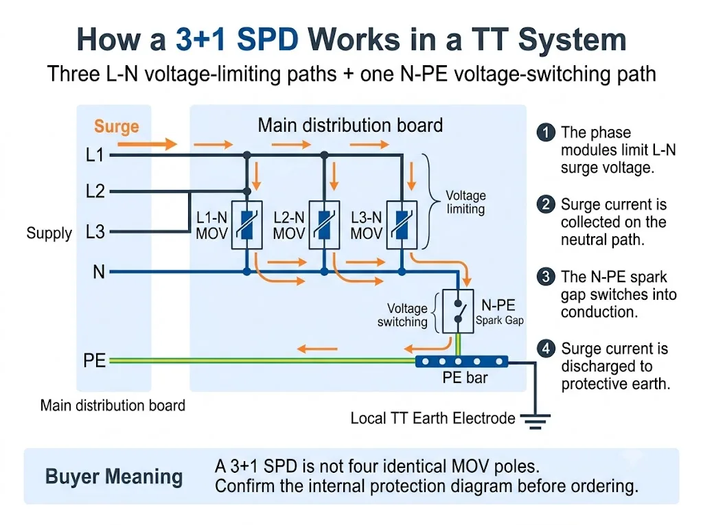
Para uma explicação mais ampla em nível de sistema, consulte o Guia de SPD do Sistema TT. Esta página permanece focada no módulo de centelhador N-PE e no seu significado para a aquisição.
3+1 vs 4+0: O que muda dentro do SPD?
Ambas as configurações podem ser comercializadas em invólucros que aparentam ter quatro polos. A diferença importante é a topologia interna de proteção.
A coluna mais importante é “Caminhos de proteção”. Ela mostra por que a contagem de polos por si só não é suficiente.
| Configuração | Caminhos de proteção | Função N-PE | O comprador deve confirmar |
|---|---|---|---|
| 3+1 | L1-N, L2-N, L3-N mais N-PE | Caminho final de descarga compartilhado do neutro para a terra | Tecnologia N-PE, classificações e dados totais da montagem |
| 4+0 | L1-PE, L2-PE, L3-PE e N-PE, ou outro arranjo condutor-PE declarado | Uma de quatro trajetórias condutor-PE em vez da trajetória comum “+1” | Circuito exato, tecnologia e adequação ao sistema de aterramento |
Conclusão de aquisição: “3P+N”, “4P”, “3+1” e “4+0” nem sempre são usados de forma consistente entre os mercados. Solicite o diagrama de circuito interno.
A comparação detalhada de configurações completas de quatro polos pertence ao Guia de SPD 3P+N vs 4P. Para esta página, o ponto principal é que um SPD 3+1 confere ao módulo N-PE uma função específica de descarga compartilhada.
O que o Gap de Faísca faz no caminho N-PE?
Um entreferro é um elemento de proteção comutado por tensão. Permanece altamente isolante durante a operação normal. Quando sua condição de comutação é atingida durante uma sobretensão, ele muda rapidamente para um estado condutor.
Depois que a sobretensão passa, um SPD baseado em entreferro CA também pode precisar extinguir a corrente fornecida pelo sistema de energia. A IEC 61643-01 e a IEC 61643-11 incluem requisitos relativos a SPDs e modos de proteção com corrente subsequente.[1][2]
Na seleção prática de N-PE, três características merecem atenção especial:
- Alta isolação entre neutro e terra durante a operação normal
- Capacidade de corrente de surto declarada durante a operação
- Comportamento de TOV e de corrente subsequente em condições CA anormais
Gap de Faísca N-PE vs Módulo MOV Comum
Uma centelha N-PE e um módulo MOV não devem ser comparados como se fossem componentes intercambiáveis. Eles utilizam princípios de funcionamento diferentes e normalmente protegem caminhos diferentes dentro da configuração 3+1.
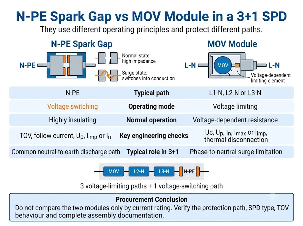
Compare primeiro a função de proteção. A corrente nominal, por si só, não mostra se dois módulos executam a mesma função.
| Ponto de decisão | Vácuo de piscar N-PE | Módulo MOV |
|---|---|---|
| Princípio de operação | Comutação de tensão | Limitação de tensão |
| Percurso típico 3+1 | N-PE | L1-N, L2-N ou L3-N |
| Estado normal | Altamente isolante antes da descarga disruptiva | Resistência dependente da tensão |
| Verificações principais em CA | Comportamento de TOV e corrente subsequente | Estabilidade térmica e desconexão |
| Classificações principais | Uc, Up, In ou Iimp, corrente total quando declarado | Uc, Up, In, Imax ou Iimp |
Conclusão de aquisição: nenhuma tecnologia é universalmente superior. A adequação depende do caminho de proteção, da classificação do SPD e do desempenho declarado do conjunto completo.
Para uma comparação mais ampla das duas tecnologias de operação, consulte o Guia de SPD com centelhador vs MOV.
O Gap de Faísca N-PE é sempre um SPD Tipo 1?
Não. A tecnologia de centelhador não torna automaticamente o SPD completo um dispositivo do Tipo 1.
A documentação oficial do produto mostra tanto descarregadores de corrente de raios Tipo 1 N-PE quanto dispositivos de centelhador Tipo 2 N-PE. A classificação deve ser confirmada na declaração e na documentação de ensaio do SPD completo ou do modo de proteção declarado.[2][5][6]
A diferença principal é a classificação de ensaio declarada, e não a aparência visual do cartucho N-PE.
| Item | Caminho N-PE Tipo 1 | Caminho N-PE Tipo 2 |
|---|---|---|
| Ensaio principal de impulso | Iimp com forma de onda de corrente de 10/350 µs | Em e, comumente, Imax com forma de onda de corrente de 8/20 µs |
| Função típica no projeto | Capacidade de condução de corrente de raio em uma posição de entrada relevante | Limitação de surtos e proteção coordenada a jusante |
| Tecnologia | Pode usar um centelhador | Também pode usar um centelhador |
| Comprovante de aprovação | Declaração completa de Tipo 1 ou Tipo 1+2 | Declaração completa de Tipo 2 |
Aviso ao comprador: não infira desempenho Tipo 1 apenas a partir das palavras “spark gap,” “N-PE” ou “proteção contra descargas atmosféricas”.
Como o módulo N-PE afeta a coordenação do RCD?
Instalações TT comumente utilizam dispositivos diferenciais residuais como parte do arranjo de proteção contra falhas. Portanto, a posição do SPD e o arranjo do RCD precisam ser analisados em conjunto.
Um caminho N-PE baseado em spark gap normalmente oferece altíssimo isolamento durante a operação normal. Isso pode ajudar a evitar um caminho neutro-terra continuamente condutivo ou continuamente submetido a tensão.
No entanto, a corrente de surto descarregada através de um DPS ainda pode afetar um IDR. O resultado depende das posições dos dispositivos, das características do IDR, do sistema de aterramento, dos modos de proteção do DPS e do arranjo da instalação. A norma IEC 61643-12 aborda a seleção, localização e coordenação de DPS, enquanto a IEC 60364-5-53 fornece a estrutura de instalação que deve ser aplicada ao projeto real.[3][4]
Os detalhes da instalação, o comprimento da conexão, a proteção de retaguarda e a relação com o DR são abordados com mais detalhe no Guia de Instalação de DPS IEC 60364-5-534.
Quais parâmetros N-PE os compradores devem verificar?
1. Modo de proteção declarado
A ficha técnica ou o diagrama do circuito devem identificar claramente o percurso N-PE. Não infira o modo de proteção pela cor do cartucho nem pela sua posição no invólucro.
2. Tensão máxima contínua de operação, Uc
Confirme o Uc declarado para o caminho N-PE. Ele pode não ser o mesmo valor usado para os módulos de fase L-N.
3. Nível de proteção contra tensão, Up
Verifique o Up declarado para N-PE, bem como o nível de proteção do modo completo ou da montagem completa. A IEC 61643-01 e a IEC 61643-11 distinguem os ensaios de DPS completos, modos de proteção e montagens de DPS.[1][2]
4. Iimp, In e Imax
Para desempenho de Tipo 1, verifique Iimp usando a forma de onda 10/350 µs. Para desempenho de Tipo 2, verifique In e, quando declarado, Imax usando a forma de onda 8/20 µs.
5. Capacidade total de descarga
Alguns produtos 3+1 declaram corrente total para a configuração completa ou para o caminho N-PE compartilhado. Não confunda esse valor com a classificação de um único cartucho L-N.
6. Comportamento frente a sobretensão temporária
TOV é uma sobretensão de frequência industrial que dura muito mais do que um impulso de surto. Confirme se o produto suporta a condição declarada ou entra em um modo de falha segura definido. Os dados de TOV específicos do produto devem ser obtidos na documentação exata do modelo.[7][8]
7. Capacidade de extinção de corrente subsequente
Quando a corrente subsequente for relevante e declarada, confirme a capacidade de extinção da centelha N-PE. Não presuma que todo projeto com centelha tenha o mesmo comportamento.[2][8]
8. Proteção de backup e dados de curto-circuito
Confirme o fusível ou disjuntor a montante exigido e a capacidade de curto-circuito do DPS completo. Não selecione a proteção de backup com base no valor de um único cartucho.
9. Substituição, indicação de estado e sinalização remota
Verifique se o elemento N-PE é substituível, se possui indicação visual de estado e se o contato remoto monitora a montagem completa.
Como verificar um SPD 3+1 antes da aprovação do OEM ou do projeto
O processo de compra mais seguro é confirmar primeiro o sistema, depois a configuração interna de proteção e, só então, aprovar as classificações elétricas e o modelo físico.
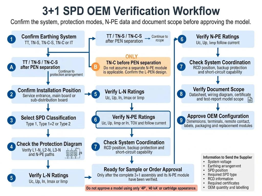
- Confirme o sistema de aterramento. Identifique se a instalação é TT, TN-S, TN-C-S, TN-C ou IT. Para TN-C-S, indique se o DPS está instalado antes ou depois da separação do PEN.
- Confirme a posição de instalação. Indique se o SPD está na entrada de serviço, no quadro geral de distribuição ou em um quadro de distribuição a jusante.
- Selecione a classificação de SPD necessária. Confirme se o projeto exige desempenho Tipo 1, Tipo 1+2 ou Tipo 2.
- Verifique o circuito interno. Confirme a configuração 1+1, 3+1, 4+0 ou outra configuração declarada no diagrama de fiação.
- Verifique separadamente os caminhos L-N e N-PE. Verifique Uc, Up e as classificações de corrente de descarga aplicáveis para cada parte.
- Revise o TOV e o comportamento da corrente subsequente. Use a ficha técnica exata do modelo. Não substitua valores por um produto visualmente semelhante.
- Verifique a coordenação do sistema. Confirme a posição do RCD, a proteção de reserva e os requisitos de curto-circuito.
- Verifique o âmbito do documento. Confirme que a ficha técnica, o certificado, o relatório de ensaio e as instruções de instalação cobrem a montagem completa real.
- Aprovar a configuração OEM. Confirmar dimensões, terminais, contacto remoto, codificação dos cartuchos, etiquetas, embalagem e referências de substituição.
Que evidências devem apoiar a aprovação do projeto?
Os gráficos técnicos explicam o circuito, mas a aprovação do projeto deve basear-se em evidências específicas do modelo. Os compradores devem solicitar documentos que identifiquem a montagem exata e o seu respetivo módulo N-PE.
Indica se o produto completo é uma configuração de proteção 3+1, 4+0 ou outra.
Lista as classificações L-N e N-PE, dados de TOV, nível de proteção e requisitos de reserva.
Confirma qual o modelo, configuração e edição da norma que estão efetivamente cobertos.
Define os terminais aprovados, a disposição dos condutores, a proteção de reserva e o processo de substituição.
As recomendações de modelos da LEEYEE devem ser confirmadas de acordo com a ficha técnica atual específica do modelo, o desenho e os documentos de conformidade disponíveis antes da amostragem ou aprovação da encomenda. O CNSPD é a plataforma da LEEYEE focada em proteção contra sobretensões para compradores técnicos globais.
Erros comuns ao solicitar um SPD N-PE ou 3+1
Encomendar apenas por “4P”
Quatro módulos visíveis não provam que o produto utilize um circuito 3+1.
Tratar todos os quatro módulos como idênticos
O descarregador N-PE (centelhador) pode utilizar tecnologia e parâmetros diferentes dos três módulos L-N.
Assumir que todos os centelhadores são Tipo 1
Também existem produtos de centelhador N-PE de Tipo 2. Confirme a classificação SPD completa.[6]
Comparar apenas o Imax
O Imax isoladamente não explica a capacidade de Tipo 1, o comportamento de TOV, a corrente de seguimento, o nível de proteção de tensão ou a classificação do conjunto completo 3+1.
Ignorar a posição do RCD
O mesmo SPD pode interagir de forma diferente com a instalação dependendo do tipo de RCD, da localização e do esquema de cablagem.
Substituir um cartucho pela aparência
Invólucros semelhantes podem ter valores de Uc, codificação, modos de proteção ou compatibilidade de base diferentes.
Verificar documentos apenas para um módulo
A ficha técnica de um cartucho não prova automaticamente que o conjunto completo 3+1 possui o âmbito de ensaio ou certificado exigido.
Antes de fazer o pedido, prepare estes detalhes
- Tensão e frequência nominal do sistema
- Sistema TT, TN-S, TN-C-S, TN-C ou IT
- Posição de instalação do SPD
- Classificação exigida de Tipo 1, Tipo 1+2 ou Tipo 2
- Configuração exigida de 1+1, 3+1, 4+0 ou outra
- Valores de Uc L-N e N-PE
- Valores de Up L-N e N-PE
- Iimp, In, Imax ou corrente total exigida
- Comportamento de TOV N-PE
- Requisito de corrente de seguimento, quando aplicável
- Informação sobre fusível ou disjuntor de reserva
- Tipo e posição de instalação do RCD
- Requisito de sinalização remota
- Largura da calha DIN e disposição dos terminais
- Norma e âmbito do certificado exigidos
- Etiqueta OEM, embalagem, quantidade e módulos de substituição
Confirme uma configuração de SPD N-PE ou 3+1
Envie a tensão do sistema, o esquema de ligação à terra, a posição de instalação, o tipo de SPD exigido, a informação sobre o RCD, o esquema de proteção e os requisitos de corrente de descarga.
A LEEYEE pode utilizar estes detalhes para analisar a configuração solicitada e preparar uma recomendação de modelo para quadros de distribuição, fornecimento de projetos ou aprovação OEM. A seleção final permanece sujeita ao projeto, às regras aplicáveis e à documentação específica do modelo.
Confirmar uma configuração de SPD OEMPerguntas Frequentes sobre SPDs de Gap de Faísca N-PE
O que significa N-PE num SPD?
N-PE identifica um caminho de proteção contra surtos entre o neutro e o condutor de proteção (terra). Em muitos produtos 3+1, este caminho utiliza um centelhador de comutação de tensão.
Por que é utilizado um centelhador N-PE num SPD 3+1?
O caminho N-PE desempenha uma função diferente dos três caminhos L-N. Proporciona a rota de descarga neutro-terra partilhada, mantendo-se altamente isolante durante o funcionamento normal.
Um SPD 3+1 é o mesmo que qualquer SPD de quatro polos?
Não. Um produto de quatro polos pode utilizar 3+1, 4+0 ou outra configuração declarada. É necessário o esquema do circuito interno.
Cada centelhador N-PE é um dispositivo de Tipo 1?
Não. A documentação oficial do produto mostra tanto descarregadores de corrente de raio N-PE de Tipo 1 como dispositivos de centelhador N-PE de Tipo 2.[5][6]
Pode um módulo MOV substituir um cartucho de centelhador N-PE?
Não sem aprovação técnica. O princípio de funcionamento, o modo de proteção, o comportamento de TOV, o comportamento da corrente de seguimento e a coordenação do conjunto completo podem ser diferentes.
Um centelhador N-PE evita disparos intempestivos do RCD?
Pode proporcionar um elevado isolamento durante o funcionamento normal, mas não pode garantir que um RCD nunca disparará. A coordenação depende da posição do SPD, das características do RCD e da configuração da instalação.
O módulo N-PE deve ter a mesma corrente nominal que os módulos de fase?
Não necessariamente. O caminho N-PE partilhado pode ser declarado utilizando dados de caminho específico ou de corrente total diferentes. Utilize a documentação completa do conjunto.
Que documentos deve um comprador OEM solicitar?
Solicite o esquema elétrico, a ficha técnica específica do modelo, as instruções de instalação, as informações sobre a proteção de reserva, o âmbito do certificado ou relatório de ensaio, o desenho dimensional e as referências dos módulos de substituição.
Referências
- Comissão Eletrotécnica Internacional, IEC 61643-01:2024, Dispositivos de proteção contra sobretensões de baixa tensão — Parte 01: Requisitos gerais e métodos de ensaio. Página de publicação oficial da IEC.
- Comissão Eletrotécnica Internacional, IEC 61643-11:2025, Dispositivos de proteção contra sobretensões de baixa tensão — Parte 11: Dispositivos de proteção contra sobretensões ligados a sistemas de alimentação de baixa tensão AC — Requisitos e métodos de ensaio. Página de publicação oficial da IEC.
- Comissão Eletrotécnica Internacional, IEC 61643-12:2020, Dispositivos de proteção contra sobretensões de baixa tensão — Parte 12: Dispositivos de proteção contra sobretensões ligados a sistemas de alimentação de baixa tensão — Princípios de seleção e aplicação. Página de publicação oficial da IEC.
- Comissão Eletrotécnica Internacional, IEC 60364-5-53:2019+AMD1:2020+AMD2:2024 CSV, Instalações elétricas de baixa tensão — Parte 5-53: Seleção e instalação de equipamento elétrico — Dispositivos de proteção para segurança, seccionamento, corte, comando e controlo. Página de publicação oficial da IEC.
- DEHN, Descarregadores de Corrente de Raio N-PE, informações oficiais de aplicação e categoria de produto para descarregadores N-PE Tipo 1 baseados em centelhador utilizados em configurações 3+1 e 1+1. Página oficial da DEHN.
- Phoenix Contact, VAL-ME-N/PE — Dispositivo de Proteção contra Sobretensões Tipo 2, informações oficiais do produto que identificam um descarregador Tipo 2 como um centelhador N-PE. Página oficial da Phoenix Contact.
- OBO Bettermann, Descarregador de Sobretensões V20, Isento de Corrente de Fuga, 3 Polos + NPE, dados oficiais de TOV e do produto específicos do modelo. Página oficial da OBO.
- OBO Bettermann, Descarregador de Sobretensões V20 com Fusível Prévio Integrado, 3+NPE, dados oficiais de TOV, proteção de reserva e corrente de seguimento N-PE específicos do modelo. Página oficial da OBO.
