
Un SPD à écart de bain N-PE est le chemin de protection contre les surtensions dédié installé entre le neutre et la terre de protection dans de nombreux arrangements 3+1 et 1+1. Il peut également être décrit comme un Parafoudre N-PE, Parafoudre de courant de foudre N-PE ou Module de protection à écart de bain N-PE.
Pour les fabricants de panneaux et les acheteurs OEM, la question importante n'est pas seulement ce qu'est le composant. Vous devez savoir pourquoi il est utilisé dans les systèmes TT, en quoi il diffère d'un module MOV ordinaire, et quelles données spécifiques au chemin doivent être vérifiées avant d'approuver le SPD complet.
Table des matières
Réponse rapide : Qu'est-ce qu'un SPD à écart de bain N-PE ?
Un SPD à écart d'étincelles N-PE est un élément de commutation de tension connecté entre le neutre et la terre de protection. En fonctionnement normal, il reste dans un état à haute impédance. Lors d'une surtension, il passe en conduction et fournit un chemin de décharge du N vers le PE.
Dans un SPD typique triphasé 3+1, trois chemins de limitation de tension protègent L1-N, L2-N et L3-N. Le quatrième chemin protège N-PE. Les parafoudres à écart d'étincelles N-PE sont utilisés dans des configurations documentées 3+1 et 1+1 pour les systèmes TT et TN sélectionnés, en fonction de la conception de l'installation et des instructions du fabricant.[3][5]
| Chemin de protection | Fonction typique | Contrôles principaux de l'acheteur |
|---|---|---|
| L1-N, L2-N, L3-N | Limiter la tension de surtension phase-neutre | Uc, Up, In, Imax ou Iimp |
| N-PE | Fournir le chemin de décharge commun neutre-terre | Uc, Up, TOV, courant de maintien, In ou Iimp |
Signification pour l'acheteur : ne jamais approuver un “SPD 4P” uniquement par le nombre de pôles. Confirmer si le circuit interne est 3+1 ou 4+0 et vérifier le chemin N-PE séparément.
Que signifie la protection N-PE ?
N signifie neutre. PE signifie terre de protection. La protection N-PE signifie que le SPD comprend un chemin de protection contre les surtensions défini entre ces deux conducteurs.
Le chemin N-PE n'est pas destiné à transporter le courant de charge normal. Son but est de contrôler une tension excessive entre le neutre et la terre lors d'un événement transitoire.
Dans un agencement 3+1, le courant de surtension des conducteurs de phase est d'abord traité par les trois chemins L-N. L'élément N-PE fournit ensuite le chemin de décharge partagé vers la terre de protection.
Pourquoi les SPDs 3+1 sont-ils courants dans les systèmes TT ?
Dans un système TT, la terre de protection de l'installation est connectée à un dispositif de mise à la terre local. Le neutre est connecté au point de mise à la terre de la source. N et PE restent séparés au sein de l'installation.
Une configuration 3+1 permet aux trois chemins de protection phase-neutre de fonctionner ensemble avec un chemin dédié de neutre à terre. La norme IEC 61643-12 fournit des principes pour le choix, le positionnement et la coordination des SPD AC, tandis que la norme IEC 60364-5-53 couvre la sélection et l'installation des dispositifs utilisés dans les installations basse tension.[3][4]
La documentation officielle du fabricant identifie également les parafoudres à éclateur N-PE pour les configurations 3+1 et 1+1 dans les systèmes TT et, selon le produit et la conception, les systèmes TN sélectionnés.[5]
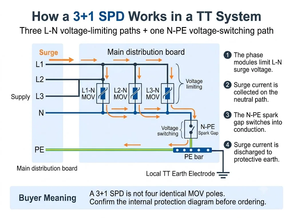
Pour une explication au niveau système plus large, voir le Guide des parafoudres SPD pour système TT. Cette page reste consacrée au module à éclateur N-PE et à sa signification pour l’approvisionnement.
3+1 contre 4+0 : Quelles sont les différences à l'intérieur du SPD ?
Les deux configurations peuvent être commercialisées dans des boîtiers qui semblent comporter quatre pôles. La différence importante réside dans la topologie interne de protection.
La colonne la plus importante est “ Voies de protection ”. Elle montre pourquoi le seul nombre de pôles ne suffit pas.
| Configuration | Chemins de protection | Fonction N-PE | L’acheteur doit confirmer |
|---|---|---|---|
| 3+1 | L1-N, L2-N, L3-N plus N-PE | Voie commune de décharge finale du neutre vers la terre | Technologie N-PE, caractéristiques assignées et données de l’ensemble complet |
| 4+0 | L1-PE, L2-PE, L3-PE et N-PE, ou une autre configuration déclarée de conducteur à PE | L’une des quatre voies conducteur-PE plutôt que la voie commune “ +1 ” | Circuit exact, technologie et compatibilité avec le système de mise à la terre |
Conclusion pour l’approvisionnement : “ 3P+N ”, “ 4P ”, “ 3+1 ” et “ 4+0 ” ne sont pas toujours employés de manière cohérente selon les marchés. Demandez le schéma électrique interne.
La comparaison détaillée des configurations complètes à quatre pôles se trouve dans le Guide des parafoudres SPD 3P+N contre 4P. Pour cette page, le point essentiel est qu’un parafoudre SPD 3+1 attribue au module N-PE un rôle spécifique de décharge commune.
Que fait l'écart de bain dans le chemin N-PE ?
Un éclateur est un élément de protection à commutation de tension. En fonctionnement normal, il reste fortement isolant. Lorsque sa condition de commutation est atteinte pendant une surtension transitoire, il passe rapidement à l’état conducteur.
Après le passage de la surtension transitoire, un parafoudre SPD à éclateur fonctionnant en courant alternatif peut également devoir interrompre le courant fourni par le réseau électrique. Les normes IEC 61643-01 et IEC 61643-11 comprennent des exigences concernant les parafoudres SPD et les modes de protection avec courant de suite.[1][2]
Dans la sélection pratique des dispositifs N-PE, trois caractéristiques méritent une attention particulière :
- Isolation élevée entre le neutre et la terre en fonctionnement normal
- Capacité déclarée à supporter les courants de surtension en fonctionnement
- Comportement en cas de TOV et de courant de suite dans des conditions anormales en courant alternatif
Écart de bain N-PE contre module MOV ordinaire
Un éclateur N-PE et un module MOV ne doivent pas être comparés comme s’il s’agissait de composants interchangeables. Ils reposent sur des principes de fonctionnement différents et protègent normalement des voies différentes au sein de la configuration 3+1.
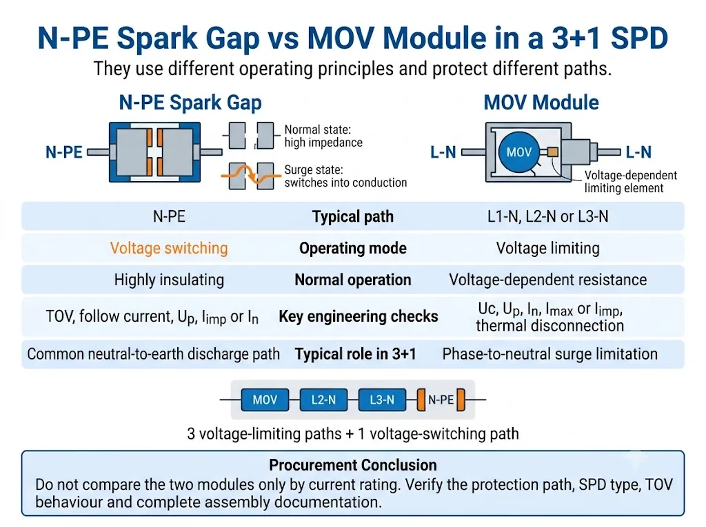
Comparez d’abord le rôle de protection. La seule intensité nominale n’indique pas si deux modules remplissent la même fonction.
| Point de décision | Éclateur N-PE | Module MOV |
|---|---|---|
| Principe de fonctionnement | Commutation de tension | Limitation de tension |
| Voie 3+1 typique | N-PE | L1-N, L2-N ou L3-N |
| État normal | Fortement isolant avant l’amorçage | Résistance dépendante de la tension |
| Vérifications clés en courant alternatif | Comportement en TOV et en courant de suite | Stabilité thermique et déconnexion |
| Évaluations principales | Uc, Up, In ou Iimp, courant total lorsqu’il est déclaré | Uc, Up, In, Imax ou Iimp |
Conclusion pour l’approvisionnement : aucune des deux technologies n’est universellement meilleure. L’adéquation dépend du chemin de protection, de la classification du SPD et des performances déclarées de l’ensemble complet.
Pour une comparaison plus large des deux technologies de fonctionnement, consultez le Guide des SPD à éclateur par rapport aux SPD à MOV.
Un écart de bain N-PE est-il toujours un SPD de type 1 ?
Non. La technologie à éclateur ne fait pas automatiquement du SPD complet un dispositif de type 1.
La documentation officielle des produits présente à la fois des parafoudres de courant de foudre N-PE de type 1 et des dispositifs N-PE à éclateur de type 2. La classification doit être confirmée à partir de la déclaration et de la documentation d’essai du SPD complet ou du mode de protection déclaré.[2][5][6]
La différence essentielle réside dans la classification d’essai déclarée, et non dans l’apparence visuelle de la cartouche N-PE.
| Article | Chemin N-PE de type 1 | Chemin N-PE de type 2 |
|---|---|---|
| Essai principal de courant de choc | Iimp avec une forme d’onde de courant de 10/350 µs | In et, généralement, Imax avec une forme d’onde de courant de 8/20 µs |
| Rôle typique dans un projet | Gestion du courant de foudre à un point d’entrée pertinent | Limitation des surtensions et protection coordonnée en aval |
| Technologie | Peut utiliser un éclateur | Peut également utiliser un éclateur |
| Justificatifs d’homologation | Déclaration complète de type 1 ou de type 1+2 | Déclaration complète de type 2 |
Avertissement à l’acheteur : ne déduisez pas les performances de type 1 de la seule présence des termes “ éclateur ”, “ N-PE ” ou “ protection contre la foudre ”.
Comment le module N-PE affecte-t-il la coordination des RCD ?
Les installations TT utilisent couramment des dispositifs différentiels résiduels dans le cadre de la protection contre les défauts. La position du parafoudre et la configuration du dispositif différentiel doivent donc être examinées conjointement.
Un chemin N-PE à éclateur fournit normalement une très forte isolation en fonctionnement ordinaire. Cela peut contribuer à éviter un chemin neutre-terre continuellement conducteur ou soumis en permanence à une tension.
Cependant, le courant de surtension dérivé par un parafoudre peut tout de même affecter un dispositif différentiel. Le résultat dépend de la position des appareils, des caractéristiques du dispositif différentiel, du schéma de mise à la terre, des modes de protection du parafoudre et de la configuration de l’installation. La norme IEC 61643-12 traite de la sélection, de l’emplacement et de la coordination des parafoudres, tandis que la norme IEC 60364-5-53 fournit le cadre d’installation qui doit être appliqué au projet concerné.[3][4]
Les détails d’installation, la longueur de raccordement, la protection de secours et la relation avec le DDR sont traités plus en détail dans le Guide d’installation des parafoudres IEC 60364-5-534.
Quels paramètres N-PE les acheteurs doivent-ils vérifier ?
1. Mode de protection déclaré
La fiche technique ou le schéma électrique doit identifier clairement le chemin N-PE. Ne déduisez pas le mode de protection de la couleur de la cartouche ou de sa position dans le boîtier.
2. Tension maximale de fonctionnement continu, Uc
Vérifiez la valeur Uc déclarée pour le chemin N-PE. Il se peut qu’elle ne soit pas identique à celle utilisée pour les modules de phase L-N.
3. Niveau de protection en tension, Up
Vérifiez la valeur Up déclarée pour N-PE ainsi que le niveau de protection du mode complet ou de l’ensemble. Les normes IEC 61643-01 et IEC 61643-11 distinguent les essais des parafoudres complets, des modes de protection et des ensembles parafoudres.[1][2]
4. Iimp, In et Imax
Pour les performances de type 1, vérifiez Iimp à l’aide de la forme d’onde 10\/350 µs. Pour les performances de type 2, vérifiez In et, lorsque cette valeur est déclarée, Imax à l’aide de la forme d’onde 8\/20 µs.
5. Capacité totale d’écoulement du courant
Certains produits 3+1 déclarent le courant total pour la configuration complète ou pour le chemin N-PE commun. Ne confondez pas cette valeur avec le calibre d’une seule cartouche L-N.
6. Comportement en cas de surtension temporaire
Une TOV est une surtension à fréquence industrielle qui dure beaucoup plus longtemps qu’une impulsion de surtension. Vérifiez si le produit résiste à la condition déclarée ou s’il entre dans un mode de défaillance sécurisée défini. Les données TOV propres au produit doivent être extraites de la documentation du modèle exact.[7][8]
7. Capacité d’extinction du courant de suite
Lorsque le courant de suite est pertinent et déclaré, vérifiez la capacité d’extinction de l’éclateur N-PE. Ne supposez pas que toutes les conceptions à éclateur présentent le même comportement.[2][8]
8. Protection de secours et données de court-circuit
Vérifiez le fusible ou le disjoncteur amont requis ainsi que la tenue au court-circuit du parafoudre complet. Ne sélectionnez pas la protection de secours à partir de la valeur d’une seule cartouche.
9. Remplacement, indication d’état et signalisation à distance
Vérifiez si l’élément N-PE est remplaçable, s’il dispose d’une indication d’état visuelle et si le contact de signalisation à distance surveille l’ensemble complet.
Comment vérifier un SPD 3+1 avant l'approbation de l'OEM ou du projet
Le processus d’achat le plus sûr consiste d’abord à confirmer le système, puis la configuration interne de protection, et seulement ensuite à valider les caractéristiques électriques et le modèle physique.
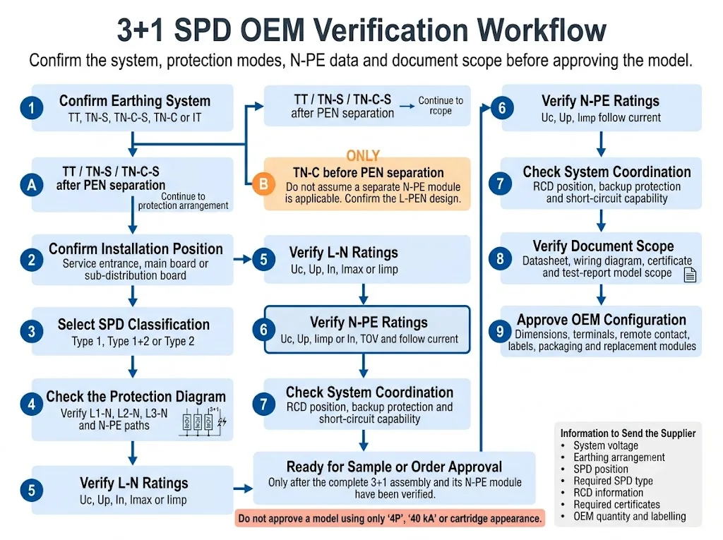
- Confirmer le système de mise à la terre. Déterminez si l’installation est de type TT, TN-S, TN-C-S, TN-C ou IT. Pour un système TN-C-S, précisez si le parafoudre est installé avant ou après la séparation du PEN.
- Confirmer la position d'installation. Précisez si le parafoudre se trouve à l’arrivée de l’installation, dans le tableau principal de distribution ou dans un tableau de distribution en aval.
- Sélectionnez la classification requise du parafoudre. Confirmez si le projet exige des performances de type 1, de type 1+2 ou de type 2.
- Vérifiez le circuit interne. Confirmez une configuration 1+1, 3+1, 4+0 ou une autre configuration déclarée à partir du schéma de câblage.
- Vérifiez séparément les chemins L-N et N-PE. Vérifiez Uc, Up ainsi que les courants de décharge nominaux applicables pour chaque pièce.
- Examinez le comportement face aux surtensions temporaires (TOV) et au courant de suite. Utilisez la fiche technique exacte du modèle. Ne substituez pas les valeurs par celles d'un produit similaire.
- Vérifiez la coordination du système. Confirmez la position du DDR, la protection de secours et les exigences en matière de court-circuit.
- Vérifiez la portée du document. Confirmez que la fiche technique, le certificat, le rapport d'essai et les instructions d'installation couvrent l'assemblage complet réel.
- Approuvez la configuration OEM. Confirmez les dimensions, les bornes, le contact distant, le codage des cartouches, les étiquettes, l'emballage et les références de remplacement.
Quelles preuves doivent soutenir l'approbation du projet ?
Les graphiques techniques expliquent le circuit, mais l'approbation du projet doit reposer sur des preuves spécifiques au modèle. Les acheteurs doivent demander des documents identifiant l'assemblage exact et son module N-PE.
Indique si le produit complet est une configuration de protection 3+1, 4+0 ou une autre disposition.
Énumère les valeurs nominales L-N et N-PE, les données TOV, le niveau de protection et les exigences de sauvegarde.
Confirme le modèle, la configuration et l'édition standard réellement couverts.
Définit les bornes approuvées, la disposition des conducteurs, la protection de secours et le processus de remplacement.
Les recommandations de modèles LEEYEE doivent être confirmées par rapport à la fiche technique, au dessin et aux documents de conformité disponibles pour le modèle spécifique avant tout échantillonnage ou approbation de commande. CNSPD est la plateforme de LEEYEE dédiée à la protection contre les surtensions pour les acheteurs techniques internationaux.
Erreurs courantes lors de la commande d'un SPD N-PE ou 3+1
Commander uniquement par « 4P »
La présence de quatre modules visibles ne prouve pas que le produit utilise un circuit 3+1.
Considérer les quatre modules comme identiques
L'éclateur N-PE peut utiliser une technologie et des paramètres différents de ceux des trois modules L-N.
En supposant que chaque éclateur soit de type 1
Il existe également des éclateurs N-PE de type 2. Veuillez confirmer la classification complète du parafoudre (SPD).[6]
Comparaison basée uniquement sur l'Imax
L'Imax ne suffit pas à expliquer la capacité de type 1, le comportement TOV, le courant de suite, le niveau de protection en tension ou la valeur nominale de l'ensemble complet 3+1.
Ignorer la position du DDR
Le même parafoudre peut interagir différemment avec l'installation selon le type de DDR, son emplacement et la configuration du câblage.
Remplacer une cartouche sur la base de son apparence
Des boîtiers similaires peuvent présenter des valeurs Uc, des codages, des modes de protection ou des compatibilités de base différents.
Vérification des documents pour un seul module
La fiche technique d'une cartouche ne prouve pas automatiquement que l'assemblage complet 3+1 dispose de la portée d'essai ou de certification requise.
Avant de commander, préparez ces détails
- Tension et fréquence nominales du système
- Régime de neutre TT, TN-S, TN-C-S, TN-C ou IT
- Position d'installation du SPD
- Classification requise de type 1, type 1+2 ou type 2
- Configuration requise 1+1, 3+1, 4+0 ou autre
- Valeurs Uc L-N et N-PE
- Valeurs Up L-N et N-PE
- Valeurs requises pour Iimp, In, Imax ou courant total
- Comportement TOV N-PE
- Exigence relative au courant de suite, le cas échéant
- Informations sur le fusible de secours ou le disjoncteur
- Type de DDR et position d'installation
- Exigence de signalisation à distance
- Largeur du rail DIN et disposition des bornes
- Norme requise et portée de la certification
- Étiquette OEM, emballage, quantité et modules de remplacement
Confirmer une configuration SPD N-PE ou 3+1
Veuillez transmettre la tension du système, le schéma de liaison à la terre, la position d'installation, le type de parafoudre requis, les informations sur le DDR, le schéma de protection ainsi que les exigences en matière de courant de décharge.
LEEYEE utilisera ces détails pour examiner la configuration demandée et préparer une recommandation de modèle pour les tableaux de distribution, l'approvisionnement de projet ou l'homologation OEM. La sélection finale demeure soumise à la conception du projet, aux règles applicables et à la documentation spécifique au modèle.
Confirmer une configuration de parafoudre OEMFAQ sur les SPDs à écart de bain N-PE
Que signifie N-PE sur un parafoudre ?
N-PE désigne un chemin de protection contre les surtensions entre le neutre et la terre de protection. Dans de nombreux produits 3+1, ce chemin utilise un éclateur à commutation de tension.
Pourquoi un éclateur N-PE est-il utilisé dans un parafoudre 3+1 ?
Le chemin N-PE remplit une fonction différente des trois chemins L-N. Il assure la voie de décharge commune entre le neutre et la terre tout en restant hautement isolant en fonctionnement normal.
Un parafoudre 3+1 est-il identique à n'importe quel parafoudre tétrapolaire ?
Non. Un produit tétrapolaire peut utiliser une configuration 3+1, 4+0 ou une autre configuration déclarée. Le schéma du circuit interne est requis.
Chaque éclateur N-PE est-il un dispositif de type 1 ?
Non. La documentation officielle du produit présente à la fois des parafoudres de type 1 N-PE et des éclateurs de type 2 N-PE.[5][6]
Un module à varistance (MOV) peut-il remplacer une cartouche à éclateur N-PE ?
Pas sans approbation technique. Le principe de fonctionnement, le mode de protection, le comportement face aux surtensions temporaires (TOV), le comportement face aux courants de suite et la coordination complète de l'assemblage peuvent différer.
Un éclateur N-PE permet-il d'éviter les déclenchements intempestifs des DDR ?
Il peut assurer une isolation élevée en fonctionnement normal, mais ne peut garantir qu'un DDR ne se déclenchera jamais. La coordination dépend de l'emplacement du parafoudre, des caractéristiques du DDR et de la configuration de l'installation.
Le module N-PE doit-il avoir le même courant nominal que les modules de phase ?
Pas automatiquement. Le chemin N-PE partagé peut être déclaré en utilisant différentes données de courant total ou spécifiques au chemin. Veuillez consulter la documentation complète de l'assemblage.
Quels documents un acheteur OEM doit-il demander ?
Demandez le schéma de circuit, la fiche technique spécifique au modèle, les instructions d'installation, les informations sur la protection de secours, la portée du certificat ou du rapport d'essai, le dessin dimensionnel et les références des modules de remplacement.
Références
- Commission électrotechnique internationale, IEC 61643-01:2024, Parafoudres basse tension — Partie 01 : Exigences générales et méthodes d'essai. Page de publication officielle de l'IEC.
- Commission électrotechnique internationale, IEC 61643-11:2025, Parafoudres basse tension — Partie 11 : Parafoudres connectés aux réseaux de distribution basse tension — Exigences et méthodes d'essai. Page de publication officielle de l'IEC.
- Commission électrotechnique internationale, IEC 61643-12:2020, Parafoudres basse tension — Partie 12 : Parafoudres connectés aux réseaux de distribution basse tension — Principes de choix et d'application. Page de publication officielle de l'IEC.
- Commission électrotechnique internationale, IEC 60364-5-53:2019+AMD1:2020+AMD2:2024 CSV, Installations électriques basse tension — Partie 5-53 : Choix et mise en œuvre des matériels électriques — Appareillages de protection pour assurer la sécurité, de sectionnement, de commande et de contrôle. Page de publication officielle de l'IEC.
- DEHN, Parafoudres N-PE,, informations officielles sur les applications et les catégories de produits pour les parafoudres N-PE de type 1 à éclateur utilisés dans les configurations 3+1 et 1+1. Page officielle DEHN.
- Phoenix Contact, VAL-ME-N/PE — Parafoudre de type 2, informations produit officielles identifiant un parafoudre de type 2 comme un éclateur N-PE. Page officielle Phoenix Contact.
- OBO Bettermann, Parafoudre V20, sans courant de fuite, 3 pôles + NPE, données produit et TOV officielles spécifiques au modèle. Page officielle OBO.
- OBO Bettermann, Parafoudre V20 avec pré-fusible intégré, 3+NPE, données officielles relatives aux TOV spécifiques au modèle, à la protection de secours et au courant de suite N-PE. Page officielle OBO.
