
Un SPD a Gap da Spark N-PE è il percorso dedicato di protezione dalle sovratensioni installato tra il neutro e la terra di protezione in molte configurazioni 3+1 e 1+1. Può essere descritto anche come un Arresto di Sovratensione N-PE, Arresto di Corrente da Fulmine N-PE o Modulo di Protezione a Gap da Spark N-PE.
Per i costruttori di pannelli e gli acquirenti OEM, la domanda importante non è solo cosa sia il componente. È necessario sapere perché viene utilizzato nei sistemi TT, come si differenzia da un modulo MOV ordinario e quali dati specifici dei percorsi devono essere verificati prima di approvare l'SPD completo.
Indice dei contenuti
Risposta Rapida: Cos'è un SPD a Gap da Spark N-PE?
Un SPD a gap di scintilla N-PE è un elemento di commutazione della tensione collegato tra il neutro e la terra protettiva. Durante il normale funzionamento, rimane in uno stato ad alta impedenza. Durante un picco, passa alla conduzione e fornisce un percorso di scarica da N a PE.
In un tipico SPD trifase 3+1, tre percorsi di limitazione della tensione proteggono L1-N, L2-N e L3-N. Il quarto percorso protegge N-PE. Gli arrestatori N-PE basati su gap di scintilla sono utilizzati in configurazioni documentate 3+1 e 1+1 per sistemi TT e TN selezionati, soggetti al design dell'installazione e alle istruzioni del produttore.[3][5]
| Percorso di protezione | Funzione tipica | Controlli principali dell'acquirente |
|---|---|---|
| L1-N, L2-N, L3-N | Limitare la tensione di picco fase-neutro | Uc, Up, In, Imax o Iimp |
| N-PE | Fornire il comune percorso di scarica neutro-terra | Uc, Up, TOV, corrente di seguimento, In o Iimp |
Significato dell'acquirente: non approvare mai un “4P SPD” solo in base al conteggio dei poli. Confermare se il circuito interno è 3+1 o 4+0 e verificare separatamente il percorso N-PE.
Cosa Significa la Protezione N-PE?
N significa neutro. PE significa terra protettiva. La protezione N-PE significa che l'SPD include un percorso di protezione contro le sovratensioni definito tra questi due conduttori.
Il percorso N-PE non è destinato a trasportare la corrente di carico normale. Il suo scopo è controllare la tensione eccessiva tra neutro e terra durante un evento transitorio.
In un'installazione 3+1, la corrente di sovratensione dai conduttori di fase è prima gestita dai tre percorsi L-N. L'elemento N-PE fornisce quindi il percorso di scarica condiviso verso la terra protettiva.
Perché gli SPD 3+1 Sono Comuni nei Sistemi TT?
In un sistema TT, la terra di protezione dell'installazione è collegata a un impianto di messa a terra locale. Il neutro è collegato al punto di messa a terra della fonte. N e PE rimangono separati all'interno dell'installazione.
Una configurazione 3+1 consente ai tre percorsi di protezione fase-neutro di lavorare insieme con un percorso dedicato neutro-terra. La norma IEC 61643-12 fornisce principi per la selezione, il posizionamento e il coordinamento degli SPD CA, mentre la norma IEC 60364-5-53 tratta della selezione e dell'installazione dei dispositivi utilizzati nelle installazioni a bassa tensione.[3][4]
La documentazione ufficiale del produttore identifica anche arrestatori N-PE a gap di sparo per configurazioni 3+1 e 1+1 nei sistemi TT e, a seconda del prodotto e del design, nei sistemi TN selezionati.[5]
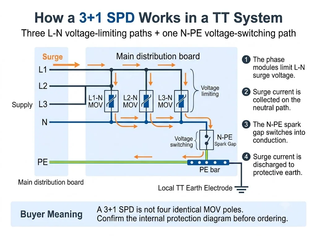
Per una spiegazione più ampia a livello di sistema, vedere il Guida agli SPD del sistema TT. Questa pagina si concentra sul modulo di gap di scintilla N-PE e sul suo significato per il procurement.
3+1 vs 4+0: Cosa Cambia All'interno dell'SPD?
Entrambi gli allestimenti possono essere venduti in involucri che sembrano avere quattro poli. La differenza importante è la topologia di protezione interna.
La colonna più importante è “Percorsi di protezione.” Mostra perché il conteggio dei poli da solo non è sufficiente.
| Allestimento | Percorsi di protezione | Funzione N-PE | L'acquirente deve confermare |
|---|---|---|---|
| 3+1 | L1-N, L2-N, L3-N più N-PE | Percorso di scarico finale condiviso da neutro a terra | Tecnologia N-PE, valutazioni e dati di assemblaggio totale |
| 4+0 | L1-PE, L2-PE, L3-PE e N-PE, o un altro allestimento dichiarato conduttore-a-PE | Uno dei quattro percorsi conduttore-a-PE piuttosto che il percorso comune “+1” | Circuito esatto, tecnologia e idoneità per il sistema di messa a terra |
Conclusione sul procurement: “3P+N,” “4P,” “3+1” e “4+0” non sono sempre usati in modo coerente nei mercati. Richiedere il diagramma interno del circuito.
Il confronto dettagliato delle configurazioni complete a quattro poli appartiene al Guida SPD 3P+N vs 4P.. Per questa pagina, il punto chiave è che un SPD 3+1 dà al modulo N-PE un ruolo specifico di scarico condiviso.
Cosa Fa il Gap da Spark nel Percorso N-PE?
Un gap di scintilla è un elemento di protezione a commutazione di tensione. Rimane altamente isolante durante il normale funzionamento. Quando viene raggiunta la sua condizione di commutazione durante un sovratensione, cambia rapidamente in uno stato conduttivo.
Dopo il passaggio della sovratensione, un SPD basato su gap di scintilla AC potrebbe anche aver bisogno di estinguere la corrente fornita dal sistema elettrico. IEC 61643-01 e IEC 61643-11 includono requisiti riguardanti gli SPD e le modalità di protezione con corrente di seguimento.[1][2]
Nella selezione pratica N-PE, tre caratteristiche meritano particolare attenzione:
- Elevata isolamento tra neutro e terra durante il normale funzionamento
- Capacità di corrente di picco dichiarata durante il funzionamento
- Comportamento TOV e di corrente di mantenimento in condizioni AC anomale
Gap da Spark N-PE vs Modulo MOV Ordinario
Un gap di scintilla N-PE e un modulo MOV non dovrebbero essere confrontati come se fossero componenti intercambiabili. Utilizzano principi di funzionamento diversi e normalmente proteggono percorsi differenti all'interno della configurazione 3+1.
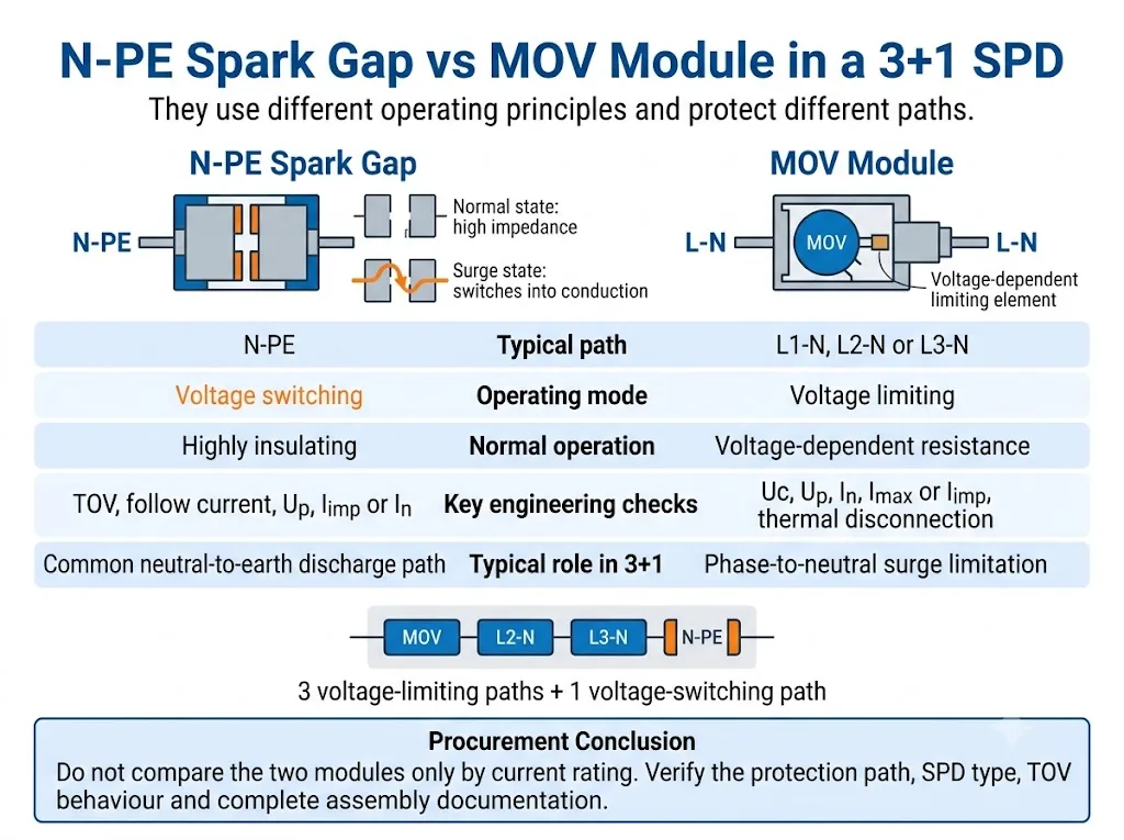
Confronta prima il ruolo di protezione. La sola valutazione della corrente non mostra se due moduli svolgono la stessa funzione.
| Punto di decisione | Gap di scintilla N-PE | Modulo MOV |
|---|---|---|
| Principio di funzionamento | Commutazione di tensione | Limitazione di tensione |
| Percorso tipico 3+1 | N-PE | L1-N, L2-N o L3-N |
| Stato normale | Altamente isolante prima della scintilla | Resistenza dipendente dalla tensione |
| Controlli chiave AC | Comportamento TOV e di corrente di mantenimento | Stabilità termica e disconnessione |
| Valutazioni chiave | Uc, Up, In o Iimp, corrente totale dichiarata | Uc, Up, In, Imax o Iimp |
Conclusione degli approvvigionamenti: nessuna delle due tecnologie è universalmente migliore. L'idoneità dipende dal percorso di protezione, dalla classificazione SPD e dalle prestazioni dichiarate dell'assemblaggio completo.
Per un confronto più ampio delle due tecnologie operative, vedere il Guida SPD Spark Gap vs MOV.
Un Gap da Spark N-PE è Sempre un SPD di Tipo 1?
No. La tecnologia a gap di scintilla non rende automaticamente l'SPD completo un dispositivo di Tipo 1.
La documentazione ufficiale del prodotto mostra sia i parafulmini di Tipo 1 N-PE che i dispositivi a gap di scintilla di Tipo 2 N-PE. La classificazione deve essere confermata dalla dichiarazione e dalla documentazione di test per l'SPD completo o la modalità di protezione dichiarata.[2][5][6]
La principale differenza è la classificazione del test dichiarata, non l'aspetto visivo del cartuccia N-PE.
| Elemento | Percorso N-PE di Tipo 1 | Percorso N-PE di Tipo 2 |
|---|---|---|
| Test principale di impulso | Iimp con forma d'onda di corrente 10/350 µs | Tra In e comunemente Imax con forma d’onda di corrente 8/20 µs |
| Ruolo tipico nel progetto | Gestione della corrente di fulmine in una posizione di ingresso pertinente | Limitazione delle sovratensioni e protezione coordinata a valle |
| Tecnologia | Può utilizzare uno spinterometro | Può anche utilizzare uno spinterometro |
| Documentazione di approvazione | Dichiarazione completa di Tipo 1 o Tipo 1+2 | Dichiarazione completa di Tipo 2 |
Avvertenza per l’acquirente: non dedurre le prestazioni di Tipo 1 dalle sole diciture “spinterometro”, “N-PE” o “protezione contro i fulmini”.
Come Influisce il Modulo N-PE sulla Coordinazione RCD?
Gli impianti TT utilizzano comunemente dispositivi differenziali come parte dell’assetto di protezione contro i guasti. La posizione del DPS e la configurazione del differenziale devono quindi essere valutate insieme.
Un percorso N-PE basato su spinterometro fornisce normalmente un isolamento molto elevato durante il funzionamento ordinario. Ciò può aiutare a evitare un percorso neutro-terra continuamente conduttivo o sottoposto a sollecitazione di tensione in modo continuo.
Tuttavia, la corrente di sovratensione scaricata attraverso un DPS può comunque influire su un differenziale. Il risultato dipende dalla posizione dei dispositivi, dalle caratteristiche del differenziale, dal sistema di messa a terra, dalle modalità di protezione del DPS e dalla configurazione dell’impianto. La IEC 61643-12 tratta la selezione, il posizionamento e il coordinamento dei DPS, mentre la IEC 60364-5-53 fornisce il quadro di installazione che deve essere applicato al progetto specifico.[3][4]
I dettagli di installazione, la lunghezza dei collegamenti, la protezione di backup e il rapporto con il differenziale sono trattati in modo più completo nella Guida all’installazione dei DPS IEC 60364-5-534.
Quali Parametri N-PE Devono Verificare gli Acquirenti?
1. Modalità di protezione dichiarata
La scheda tecnica o lo schema del circuito dovrebbero identificare chiaramente il percorso N-PE. Non dedurre la modalità di protezione dal colore della cartuccia o dalla sua posizione nell’involucro.
2. Tensione massima continua di esercizio, Uc
Verificare la Uc dichiarata per il percorso N-PE. Potrebbe non coincidere con il valore utilizzato per i moduli di fase L-N.
3. Livello di protezione della tensione, Up
Controllare l’Up dichiarato per N-PE, così come il livello di protezione della modalità o dell’assemblaggio completo. IEC 61643-01 e IEC 61643-11 distinguono le prove degli SPD completi, delle modalità di protezione e degli assemblaggi SPD.[1][2]
4. Iimp, In e Imax
Per le prestazioni di Tipo 1, verificare Iimp utilizzando la forma d’onda 10/350 µs. Per le prestazioni di Tipo 2, verificare In e, se dichiarato, Imax utilizzando la forma d’onda 8/20 µs.
5. Capacità totale di scarica
Alcuni prodotti 3+1 dichiarano la corrente totale per l’assetto completo o per il percorso N-PE condiviso. Non confondere questo valore con il valore nominale di una singola cartuccia L-N.
6. Comportamento in caso di sovratensione temporanea
La TOV è una sovratensione a frequenza di rete che dura molto più a lungo di un impulso di sovratensione. Verificare se il prodotto sopporta la condizione dichiarata o entra in una modalità di guasto sicura definita. I dati TOV specifici del prodotto devono essere presi dalla documentazione del modello esatto.[7][8]
7. Capacità di estinzione della corrente susseguente
Laddove la corrente susseguente sia rilevante e dichiarata, verificare la capacità di estinzione della scarica a scintilla N-PE. Non dare per scontato che ogni progettazione con spinterometro abbia lo stesso comportamento.[2][8]
8. Protezione di backup e dati di cortocircuito
Verificare il fusibile o l’interruttore automatico a monte richiesto e la capacità di cortocircuito dell’SPD completo. Non selezionare la protezione di backup in base al valore di una singola cartuccia.
9. Sostituzione, indicazione di stato e segnalazione remota
Verificare se l’elemento N-PE è sostituibile, se dispone di indicazione visiva di stato e se il contatto remoto monitora l’assemblaggio completo.
Come Verificare un SPD 3+1 Prima dell'Approvazione OEM o di Progetto
Il processo di acquisto più sicuro consiste nel confermare prima il sistema, poi la configurazione interna di protezione e solo successivamente approvare i valori elettrici e il modello fisico.
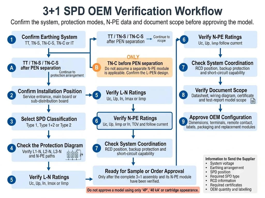
- Confermare il sistema di messa a terra. Identificare se l’impianto è TT, TN-S, TN-C-S, TN-C o IT. Per TN-C-S, indicare se l’SPD è installato prima o dopo la separazione del PEN.
- Conferma la posizione di installazione. Indicare se l'SPD si trova all'ingresso dell'impianto, nel quadro di distribuzione principale o nel quadro di distribuzione a valle.
- Selezionare la classificazione SPD richiesta. Confermare se il progetto richiede prestazioni di Tipo 1, Tipo 1+2 o Tipo 2.
- Verificare il circuito interno. Confermare 1+1, 3+1, 4+0 oppure un'altra configurazione dichiarata nello schema di cablaggio.
- Controllare separatamente i percorsi L-N e N-PE. Verificare Uc, Up e le relative portate di corrente di scarica per ciascuna parte.
- Esaminare il comportamento in caso di TOV e di corrente susseguente. Utilizzare la scheda tecnica esatta del modello. Non sostituire i valori con quelli di un prodotto simile.
- Verificare il coordinamento del sistema. Verificare la posizione dell'RCD, la protezione di riserva e i requisiti di cortocircuito.
- Verificare l'ambito del documento. Confermare che la scheda tecnica, il certificato, il rapporto di prova e le istruzioni di installazione coprano l'intero assieme effettivo.
- Approvare la configurazione OEM. Confermare dimensioni, terminali, contatto remoto, codifica delle cartucce, etichette, imballaggio e riferimenti di ricambio.
Quali Prove Dovrebbero Sostenere l'Approvazione del Progetto?
I grafici tecnici spiegano il circuito, ma l'approvazione del progetto deve basarsi su prove specifiche per il modello. Gli acquirenti dovrebbero richiedere documenti che identifichino l'assieme esatto e il relativo modulo N-PE.
Mostra se il prodotto completo è 3+1, 4+0 o un'altra disposizione di protezione.
Elenca le caratteristiche nominali L-N e N-PE, i dati TOV, il livello di protezione e i requisiti di backup.
Conferma quale modello, configurazione ed edizione dello standard sono effettivamente coperti.
Definisce i terminali approvati, la disposizione dei conduttori, la protezione di backup e il processo di sostituzione.
Le raccomandazioni sui modelli LEEYEE devono essere confermate rispetto alla scheda tecnica specifica per il modello corrente, al disegno e ai documenti di conformità disponibili prima del campionamento o dell'approvazione dell'ordine. CNSPD è la piattaforma di LEEYEE incentrata sulla protezione contro le sovratensioni per gli acquirenti tecnici globali.
Errori Comuni Quando si Ordina un SPD N-PE o 3+1
Ordinare solo tramite “4P”
Quattro moduli visibili non provano che il prodotto utilizzi un circuito 3+1.
Trattare tutti e quattro i moduli come identici
Lo spinterometro N-PE potrebbe utilizzare una tecnologia e parametri diversi rispetto ai tre moduli L-N.
Assumere che ogni spinterometro sia di Tipo 1
Esistono anche prodotti con spinterometro N-PE di Tipo 2. Confermare la classificazione completa dell'SPD.[6]
Confrontare solo l'Imax
L'Imax da solo non spiega la capacità di Tipo 1, il comportamento TOV, la corrente di seguito, il livello di protezione della tensione o la classificazione dell'intero assieme 3+1.
Ignorare la posizione dell'RCD
Lo stesso SPD può interagire in modo diverso con l'installazione a seconda del tipo di RCD, della posizione e della disposizione del cablaggio.
Sostituzione di una cartuccia in base all'aspetto
Involucri simili possono avere valori Uc, codifica, modi di protezione o compatibilità di base differenti.
Controllo dei documenti per un solo modulo
La scheda tecnica di una cartuccia non dimostra automaticamente che l'intero assemblaggio 3+1 abbia il campo di applicazione richiesto dai test o dai certificati.
Prima di Ordinare, Prepara Questi Dettagli
- Tensione e frequenza nominali del sistema
- Sistema TT, TN-S, TN-C-S, TN-C o IT
- Posizione di installazione dell'SPD
- Classificazione richiesta Tipo 1, Tipo 1+2 o Tipo 2
- Configurazione richiesta 1+1, 3+1, 4+0 o altra
- Valori Uc L-N e N-PE
- Valori Up L-N e N-PE
- Iimp, In, Imax o corrente totale richiesta
- Comportamento TOV N-PE
- Requisito della corrente di seguito dove applicabile
- Informazioni sul fusibile di backup o sull'interruttore automatico
- Tipo di RCD e posizione di installazione
- Requisito di segnalazione remota
- Larghezza della barra DIN e disposizione dei morsetti
- Standard richiesto e campo di applicazione del certificato
- Etichetta OEM, imballaggio, quantità e moduli di ricambio
Conferma una Configurazione SPD N-PE o 3+1
Inviare la tensione di sistema, il tipo di collegamento a terra, la posizione di installazione, il tipo di SPD richiesto, le informazioni sull'RCD, lo schema di protezione e i requisiti della corrente di scarica.
LEEYEE può utilizzare questi dettagli per esaminare la configurazione richiesta e preparare una raccomandazione sui modelli per quadri di distribuzione, fornitura di progetti o approvazione OEM. La selezione finale rimane soggetta al design del progetto, alle norme applicabili e alla documentazione specifica del modello.
Confermare una configurazione SPD OEMFAQ Sugli SPD a Gap da Spark N-PE
Cosa significa N-PE su un SPD?
N-PE identifica un percorso di protezione contro le sovratensioni tra il neutro e la terra di protezione. In molti prodotti 3+1, questo percorso utilizza uno spinterometro a commutazione di tensione.
Perché viene utilizzato uno spinterometro N-PE in un SPD 3+1?
Il percorso N-PE svolge una funzione diversa rispetto ai tre percorsi L-N. Esso fornisce la via di scarica condivisa tra neutro e terra, mantenendo un elevato isolamento durante il normale funzionamento.
Un SPD 3+1 è uguale a qualsiasi SPD a quattro poli?
No. Un prodotto a quattro poli può utilizzare una configurazione 3+1, 4+0 o un'altra configurazione dichiarata. È necessario lo schema elettrico interno.
Ogni spinterometro N-PE è un dispositivo di Tipo 1?
No. La documentazione ufficiale del prodotto mostra sia scaricatori di corrente da fulmine N-PE di Tipo 1 che dispositivi a spinterometro N-PE di Tipo 2.[5][6]
Un modulo MOV può sostituire una cartuccia con spinterometro N-PE?
Non senza approvazione tecnica. Il principio di funzionamento, il modo di protezione, il comportamento TOV, il comportamento della corrente di seguito e il coordinamento dell'intero assemblaggio potrebbero essere diversi.
Uno spinterometro N-PE previene gli scatti intempestivi dell'RCD?
Può fornire un elevato isolamento durante il normale funzionamento, ma non può garantire che un RCD non intervenga mai. Il coordinamento dipende dalla posizione dell'SPD, dalle caratteristiche dell'RCD e dalla disposizione dell'installazione.
Il modulo N-PE deve avere la stessa corrente nominale dei moduli di fase?
Non automaticamente. Il percorso N-PE condiviso può essere dichiarato utilizzando dati specifici del percorso o di corrente totale differenti. Utilizzare la documentazione completa dell'assemblaggio.
Quali documenti dovrebbe richiedere un acquirente OEM?
Richiedere lo schema elettrico, la scheda tecnica specifica del modello, le istruzioni di installazione, le informazioni sulla protezione di backup, il campo di applicazione del certificato o del rapporto di prova, il disegno dimensionale e i riferimenti dei moduli di ricambio.
Riferimenti
- Commissione Elettrotecnica Internazionale, IEC 61643-01:2024, Dispositivi di protezione contro le sovratensioni a bassa tensione — Parte 01: Requisiti generali e metodi di prova. Pagina ufficiale della pubblicazione IEC.
- Commissione Elettrotecnica Internazionale, IEC 61643-11:2025, Dispositivi di protezione contro le sovratensioni a bassa tensione — Parte 11: Dispositivi di protezione contro le sovratensioni collegati a sistemi di alimentazione a bassa tensione in corrente alternata — Requisiti e metodi di prova. Pagina ufficiale della pubblicazione IEC.
- Commissione Elettrotecnica Internazionale, IEC 61643-12:2020, Dispositivi di protezione contro le sovratensioni a bassa tensione — Parte 12: Dispositivi di protezione contro le sovratensioni collegati a sistemi di alimentazione a bassa tensione — Principi di selezione e applicazione. Pagina ufficiale della pubblicazione IEC.
- Commissione Elettrotecnica Internazionale, IEC 60364-5-53:2019+AMD1:2020+AMD2:2024 CSV, Impianti elettrici a bassa tensione — Parte 5-53: Scelta ed installazione dei componenti elettrici — Dispositivi per la protezione per la sicurezza, isolamento, sezionamento, comando e monitoraggio. Pagina ufficiale della pubblicazione IEC.
- DEHN, Scaricatori di corrente da fulmine N-PE, informazioni ufficiali sull'applicazione e sulla categoria di prodotto per gli scaricatori N-PE di Tipo 1 basati su spinterometro utilizzati nelle configurazioni 3+1 e 1+1. Pagina ufficiale DEHN.
- Phoenix Contact, VAL-ME-N/PE — Dispositivo di protezione contro le sovratensioni di Tipo 2, informazioni ufficiali sul prodotto che identificano uno scaricatore di Tipo 2 come uno spinterometro N-PE. Pagina ufficiale Phoenix Contact.
- OBO Bettermann, Scaricatore di sovratensioni V20, privo di corrente di dispersione, 3 poli + NPE, dati ufficiali sul prodotto e TOV specifici per il modello. Pagina ufficiale OBO.
- OBO Bettermann, Scaricatore di sovratensioni V20 con pre-fusibile integrato, 3+NPE, TOV specifico per il modello ufficiale, protezione di backup e dati sulla corrente residua N-PE. Pagina ufficiale OBO.
