AC Type 1+2 SPD · Class I+II

Type 1+2 Surge Protective Devices

Combined lightning-current and surge protection for main distribution boards, distributors, panel builders and OEM projects. Send Uc, Iimp, poles and earthing system to confirm the correct model and document scope.

10/350μs Iimp 8/20μs In / Imax 75–440V AC Uc 1P to 3P+N MOV / MOV+GDT Módulos plugáveis
Compare Poles & System
One combined Type 1+2 device is not the same as two coordinated SPDs.
Main distribution applicationsFor incoming panels where lightning-current and surge performance are both required.
Combined test parametersIimp at 10/350μs plus In/Imax at 8/20μs must be checked by exact version.
Model-specific document reviewVoltage, poles, branding and certificate scope are confirmed before quotation.
Seleção Rápida

Start With the Installation Point, System and Protection Mode

A Type 1+2 SPD should not be selected by pole count alone. Confirm where it is installed, how neutral and PE are arranged, the required Iimp path, Uc and the external backup protection.

01

Use Type 1+2 at the incoming stage

It is commonly considered for main distribution boards and buildings with an external lightning protection system when one device must provide both lightning-current and surge performance.

02

Match the protection topology

3P, 4P and 3P+N are not interchangeable labels. The correct arrangement depends on TT, TN-S or TN-C conductors and whether the design uses 4+0 or 3+1 protection.

03

Check each current path

For MOV+GDT arrangements, L-N and N-PE values can differ. Ask whether Iimp is stated per pole, per protection path or as a total value.

Typical AC system starting pointsFinal selection requires the actual wiring diagram and project conditions.
Sistema ACCommon starting configurationProtection conceptKey confirmation before order
Single-phase TN-S / TT1P+N or verified 2P arrangementL-N plus N-PE, or all-mode arrangement according to designUc, N-PE path, Iimp allocation and backup protection
Three-phase TN-C3PPhase-to-PEN conductors without a separate neutral at the installation pointActual PEN arrangement, Uc and short-circuit conditions
Three-phase TN-S4P ou 3P+N4+0 or 3+1 depending project topologyNeutral treatment, N-PE path, Up and conductor routing
Three-phase TTVerified 3P+N arrangementCommonly L-N MOV paths plus N-PE GDT pathN-PE impulse current, follow current and document coverage
This table is a procurement starting point, not a substitute for the project single-line diagram, local installation requirements or coordination study.
Type Comparison

Do Not Confuse Type 1+2 With Type 1 or Type 2

The classification changes the test parameters, expected installation stage and procurement checks. The page below focuses only on the combined Type 1+2 product range.

Tipo 1

Lightning-current duty

Designed around the 10/350μs lightning-current test and Iimp performance.

  • Primary parameter: Iimp
  • Typical stage: service entrance or main board
  • Separate downstream coordination may still be required
This page Tipo 1+2

Combined performance

One SPD evaluated for both 10/350μs lightning-current and 8/20μs surge-current performance.

  • Key parameters: Iimp, In, Imax and Up
  • Typical stage: main distribution board
  • Must verify voltage, poles and protection mode
Tipo 2

Induced and switching surges

Designed around the 8/20μs test using In and Imax as the main current parameters.

  • Primary parameters: In and Imax
  • Typical stage: sub-distribution or equipment panels
  • Not a direct substitute for a required Type 1 stage
Type 1+2 Product Range

Select the LY1-12.5 Series by Poles and Protection Path

Six existing configurations cover single-path, multi-pole and MOV+GDT arrangements. Exact Uc, Up, Iimp, In and backup-fuse data are checked against the selected version.
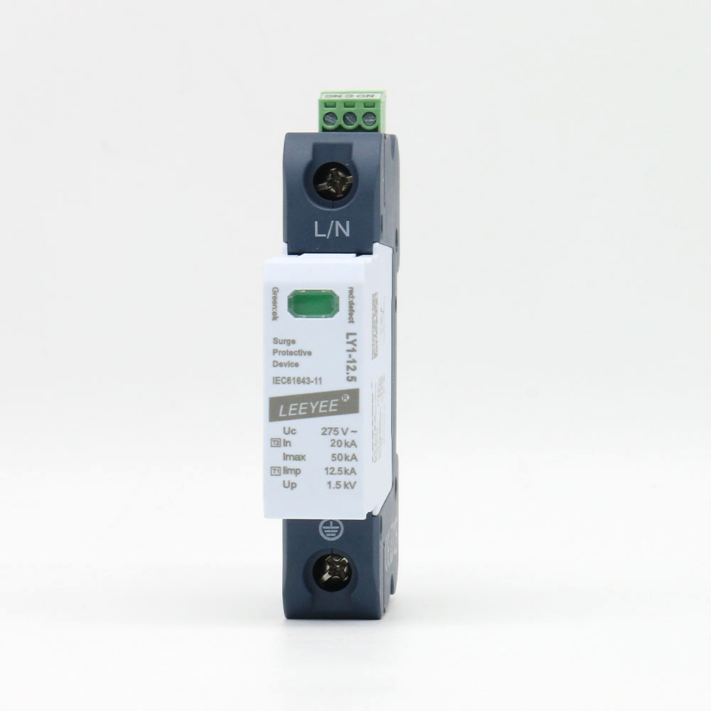
1 Pole LY1-12.5/1(S) single pole Type 1+2 surge protective device

LY1-12.5/1(S)

Single-pole pluggable Type 1+2 module for a verified protection path.

Uc range75–440V AC
Iimp10–12.5kA by Uc
In / Imax20kA / 50kA
Sinal remotoOptional “S” version

Higher-Uc versions can have different Iimp and backup-fuse limits. Confirm the exact voltage suffix.
View Details
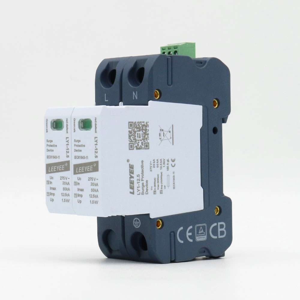
2 Pole LY1-12.5/2(S) two pole Type 1+2 surge protective device

LY1-12.5/2(S)

Two-pole pluggable assembly for a system design requiring two protected conductors.

Uc range75–440V AC
Iimp10–12.5kA by version
Em10/20kA by version
Imax50kA

A 2P enclosure does not by itself prove the correct L-N/N-PE topology. Verify the internal protection mode.
View Details
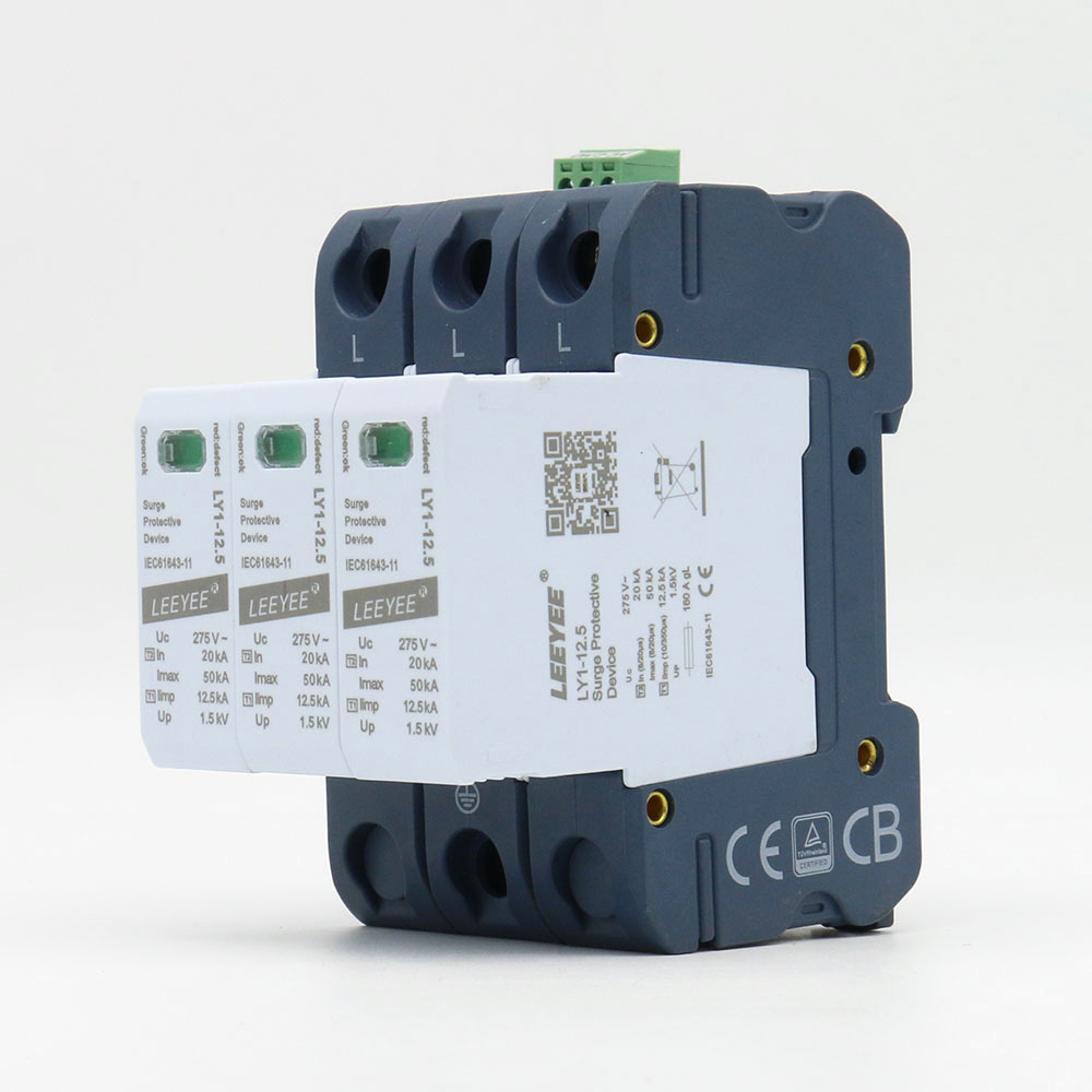
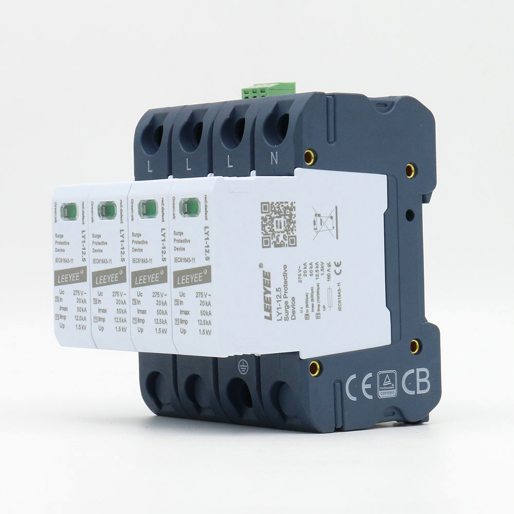
3 Pole LY1-12.5/3(S) three pole Type 1+2 surge protective device

LY1-12.5/3(S)

Three-pole pluggable Type 1+2 SPD for verified three-conductor arrangements.

Uc range75–440V AC
Iimp10–12.5kA by version
Em10/20kA by version
Imax50kA

Commonly considered where no separate neutral conductor is protected at the installation point. Confirm the actual system.
View Details
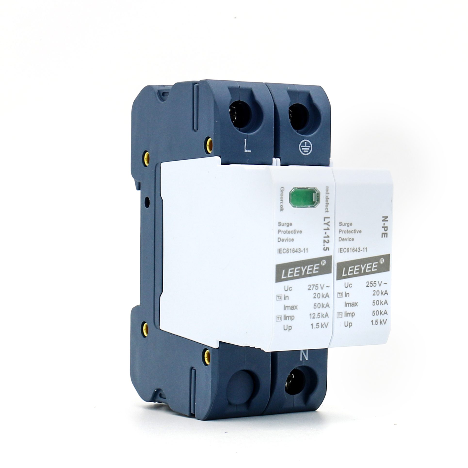
4 Pole LY1-12.5/4(S) four pole Type 1+2 surge protective device

LY1-12.5/4(S)

Four-pole pluggable Type 1+2 SPD for a verified 4+0 protection arrangement.

Uc range75–440V AC
Iimp10–12.5kA by version
Em10/20kA by version
Imax50kA

Do not treat “4P” as automatically identical to a 3+1 MOV+GDT configuration. Check the protection paths.
View Details
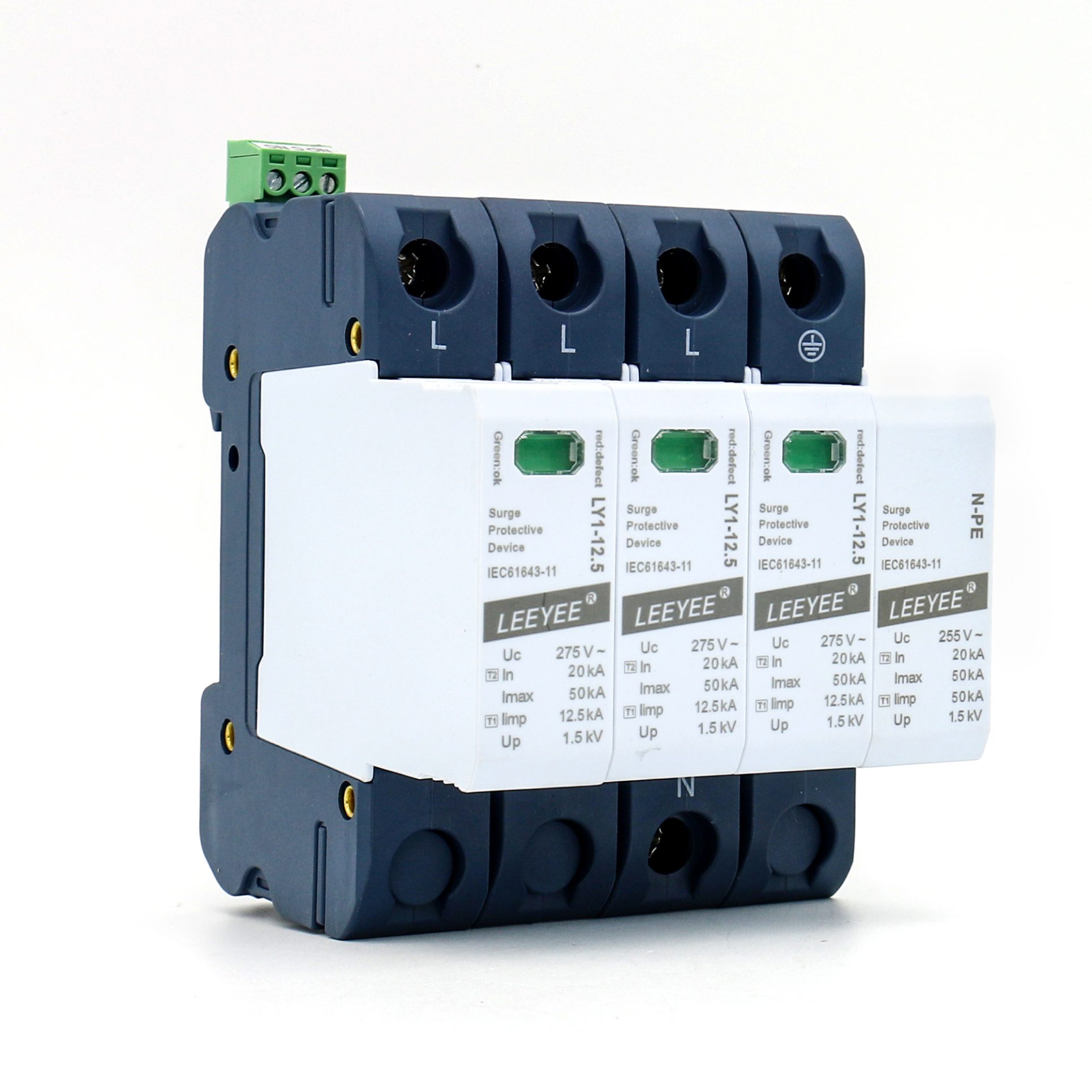
1P+N · MOV+GDT LY1-12.5/1(S)+1 one pole plus neutral Type 1+2 surge protective device

LY1-12.5/1(S)+1

L-N MOV plus N-PE GDT arrangement for a verified single-phase topology.

Uc L-N / N-PE75–320V / 255V
Iimp L-N / N-PE12.5 / 25kA
In L-N / N-PE20 / 25kA
Imax L-N / N-PE50 / 50kA

Confirm N-PE follow-current behavior, Up and the external backup-fuse requirement for the exact version.
View Details
3P+N · MOV+GDT LY1-12.5/3(S)+1 three phase plus neutral Type 1+2 surge protective device

LY1-12.5/3(S)+1

Three L-N MOV paths plus one N-PE GDT path for a verified 3+1 topology.

Uc L-N / N-PE75–320V / 255V
Iimp L-N / N-PE12.5 / 50kA
In L-N / N-PE20 / 50kA
Imax L-N / N-PE50 / 100kA

L-N and N-PE values are intentionally different. Review each path instead of relying on one headline current value.

View Details
Procurement Approval

Four Checks That Prevent the Wrong Type 1+2 Order

A model can look correct by Type and pole count but still be unsuitable because the current path, Uc, topology or backup protection was not verified.

1. Iimp per pole, path or total

Ask how the declared 10/350μs current is allocated. A headline number can refer to one pole, one path or a complete N-PE path depending on the model.

2. Uc and expected voltage conditions

Choose Uc against the actual phase-to-neutral or phase-to-earth voltage, tolerances and temporary overvoltage exposure. Higher Uc is not automatically better.

3. 4+0 versus 3+1 topology

A 4P MOV arrangement and a 3P+N MOV+GDT arrangement create different paths. Confirm neutral handling, N-PE behavior and the project earthing system.

4. External fuse or MCB coordination

The SPD’s internal thermal disconnector does not replace all external short-circuit protection. Check the maximum backup fuse, prospective fault current and conductor length.

Send the single-line diagram or panel requirement

LEEYEE can review system voltage, Type, poles, current parameters, remote contact and document scope before quotation.

Testing Evidence

Verify the Components, Impulse Performance and Thermal Safety

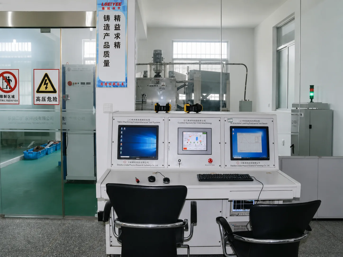
Equipment photos are supporting evidence, not a substitute for a model-specific test report. The exact Type, Uc, poles and branding configuration must still match the document scope.
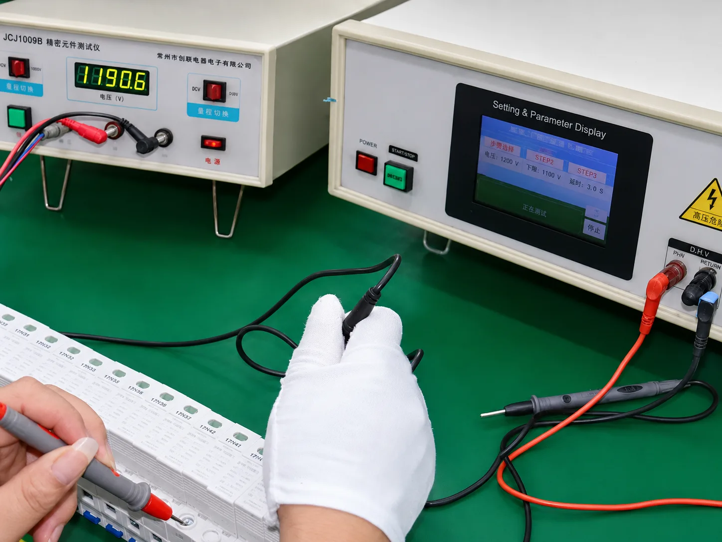
01MOV and GDT component tester for Type 1 plus 2 surge protective devices

MOV and GDT validation

Core protective components are checked before they become part of a finished SPD assembly.

  • Varistor and gas-discharge-tube screening
  • Component-level consistency checks
  • Supports batch control, not certificate substitution
02Lightning impulse generator used for surge protective device testing

Impulse-current verification

Type 1+2 procurement requires evidence for both lightning-current and surge-current performance, according to the exact model.
  • 10/350μs Iimp review
  • 8/20μs In and Imax review
  • Up and protection-path confirmation
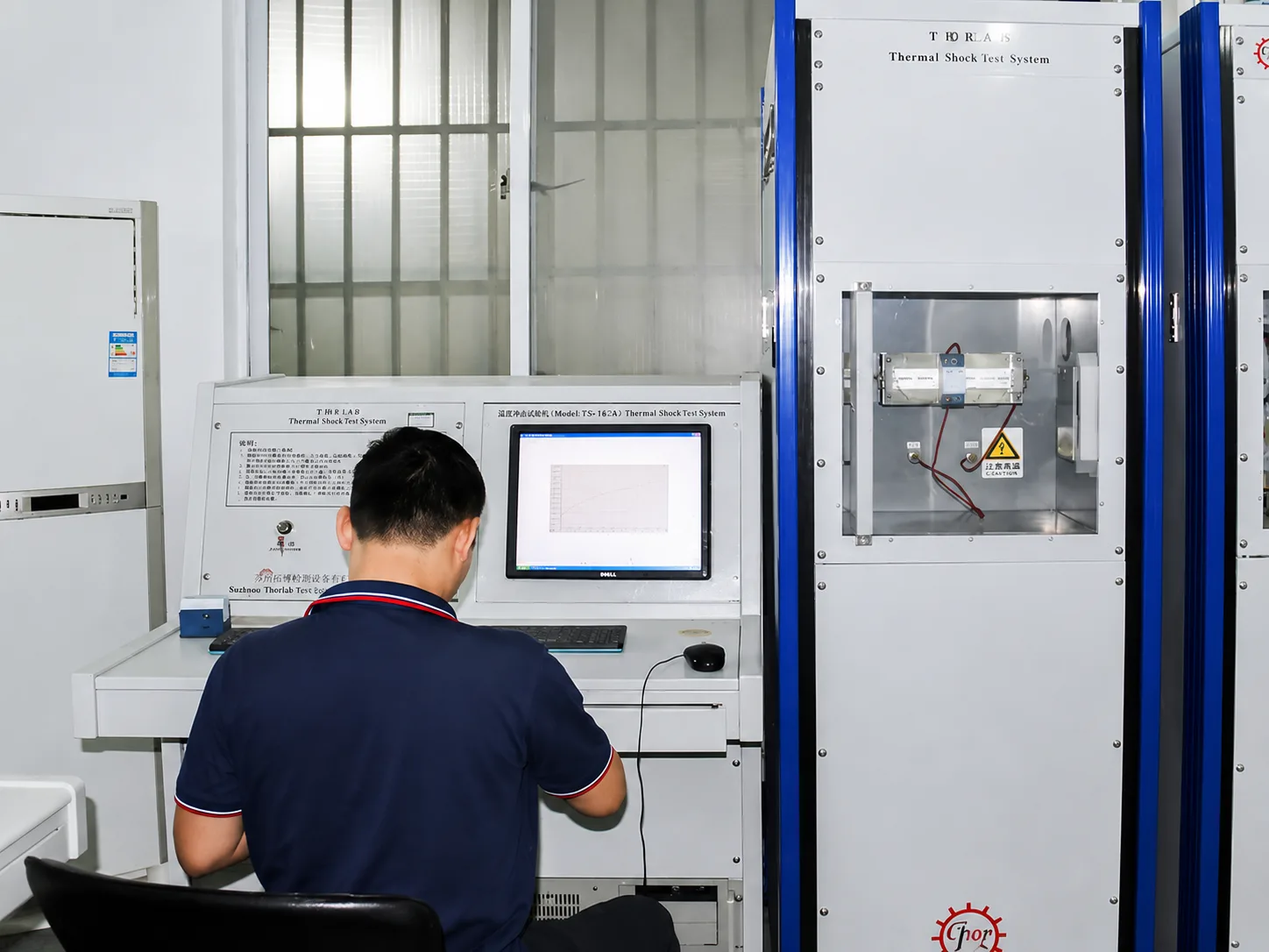
03Thermal stability test for surge protective device safety validation

Thermal stability and disconnection

Thermal behavior matters because MOV ageing and abnormal voltage exposure can create a safety risk if disconnection is unreliable.

  • Thermal response observation
  • Disconnector-function review
  • Failure-safety evidence by exact product version

Document boundary: Certification and test-document availability depends on the exact model, voltage, SPD Type, pole configuration, brand and manufacturer information. Submit the required version for confirmation.

OEM & Project Documents

Keep the Product, Label, Packaging and Files Consistent

For distributors, panel builders and private-label buyers, commercial approval is not complete until the selected model and all customer-facing documents describe the same product.

What can be reviewed before order

Share the intended market, system, quantity and branding requirement so LEEYEE can identify the relevant model and available documentation.

  • Type 1+2 model, Uc, poles, Iimp, In, Imax and Up
  • Remote-contact option, module format and backup-protection data
  • Data sheet, CE, TÜV, CB, RoHS and IEC-related file availability by model
  • Logo, label, model naming, packaging, instructions and carton requirements
Do not assume that one certificate covers every voltage, pole arrangement or private-label configuration. File scope must be checked before artwork or purchase approval.

Recommended approval workflow

A short approval sequence reduces the risk of ordering the correct enclosure with the wrong electrical or document configuration.

01
Send system and project requirementVoltage, earthing system, poles, Iimp, quantity, timing and market.
02
Confirm model and document scopeReview product version, available files and any branding limitations.
03
Approve sample or artworkCheck product label, packaging, instructions and selected model details.
04
Release production and inspectionUse the approved configuration as the reference for batch supply.
Perguntas frequentes sobre SPD Tipo 1+2

Type 1+2 SPD Questions Before Quotation

These answers cover the most common procurement errors. For a model recommendation, send the actual system voltage, earthing arrangement, poles and quantity.

O que significa SPD Tipo 1+2?
It means one SPD has combined classification and is evaluated for both Type 1 lightning-current performance using the 10/350μs waveform and Type 2 surge-current performance using the 8/20μs waveform.
Is one Type 1+2 SPD the same as installing separate Type 1 and Type 2 SPDs?
No. A combined device and a coordinated two-stage installation are different design approaches. The required arrangement depends on the protection concept, installation distance, equipment sensitivity and project rules.
Should I choose 1P, 2P, 3P, 4P or 3P+N?
Pole count must follow the conductors and protection topology at the installation point. Confirm the TT, TN-S or TN-C system, whether neutral is present and whether the design requires a 4+0 or 3+1 arrangement.
How should I select 275V, 320V, 385V or 440V Uc?
Uc must be high enough for the actual continuous voltage and expected tolerances without becoming unnecessarily high. The correct choice also depends on phase-to-neutral or phase-to-earth connection and temporary overvoltage conditions.
Is Iimp 12.5kA stated per pole or for the complete SPD?
It must be checked in the exact product data. Depending on the topology, values may be stated per pole, per L-N path, for the N-PE path or as a total value. Do not compare products using one headline number alone.
Does the internal thermal disconnector replace the external fuse or MCB?
No. Internal thermal disconnection and external short-circuit backup protection perform different functions. Check the manufacturer’s maximum backup-fuse data and the project prospective short-circuit current.
Can an AC Type 1+2 SPD be used on a solar PV DC circuit?
No assumption should be made. AC and PV DC SPDs have different voltage, extinguishing and standard requirements. Use a dedicated DC/PV SPD selected for the maximum PV system conditions.
Are CE, TÜV and CB documents available for every LY1-12.5 version?
Availability must be confirmed against the exact Uc, pole configuration, Type, model name, brand and manufacturer information. Submit the intended model and market for document review.

Brand clarification: LEEYEE is the product brand. CNSPD.com is LEEYEE’s surge-protection platform for global buyers.

Confirm Type 1+2 SPD Model

Send Your System Requirement

Provide enough information for the first reply to focus on the correct topology, model version, document scope and quotation conditions.

Model shortlistPoles & topology checkDocument reviewQuantity-based quote
Add buyer and document details (optional)

Your information is used only to review the SPD requirement and respond to the inquiry.