
Os tipos 1, 2 e 3 não são três níveis de qualidade. Eles descrevem diferentes ensaios e funções de instalação do SPD. Um sistema coordenado de proteção contra surtos deve definir onde cada estágio se aplica, como os estágios compartilham a energia do surto e se a tensão que chega ao equipamento final é baixa o suficiente.
Um único SPD pode ser suficiente para uma instalação compacta e de baixa exposição, mas não se deve presumir que um único dispositivo proteja um edifício ou projeto inteiro.
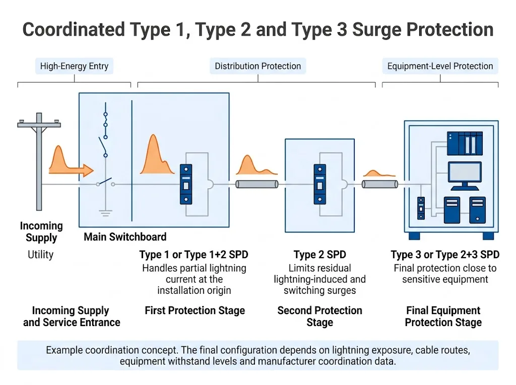
Onde uma corrente parcial de raio possa entrar na instalação elétrica, normalmente avalia-se um SPD do Tipo 1 ou Tipo 1+2 na origem. Os SPDs do Tipo 2 são usados nos pontos principais de distribuição ou a jusante para limitar surtos residuais induzidos por raios e surtos de manobra. A proteção do Tipo 3 ou Tipo 2+3 é considerada próxima a equipamentos sensíveis quando o estágio a montante não consegue manter um nível de proteção suficientemente baixo na carga. [1] [3] [4] [5]
A configuração correta pode, portanto, ser apenas Tipo 2, um SPD combinado Tipo 1+2, estágios separados Tipo 1 e Tipo 2, ou uma cadeia completa de proteção Tipo 1–Tipo 2–Tipo 3. A escolha final depende da arquitetura do projeto, do nível de suportabilidade do equipamento, dos trajetos dos condutores e dos dados de coordenação do fabricante.
Índice
Neste Guia
- O que significa coordenação de SPD
- Três verificações que não devem ser confundidas
- Quando um único SPD pode ser suficiente
- Onde os Tipos 1, 2 e 3 se enquadram
- Como projetar os estágios de proteção
- Quando os Tipos 1 e 2 funcionam em conjunto
- Quando os equipamentos precisam de Tipo 3
- Coordenação de distância e energia
- SPDs combinados versus separados
- Exemplo prático de engenharia
- Aplicações em data center, industrial, PV, EV e BESS
- Aprovação de coordenação em nível de modelo
- Lista de verificação para compras e OEM
- Erros comuns de coordenação
- FAQ
O que realmente significa coordenação de SPD?
Coordenação de SPD significa que dois ou mais estágios de proteção operam como um sistema planejado. O SPD a montante gerencia a solicitação de surto esperada em sua posição. O SPD a jusante limita ainda mais a tensão restante sem receber mais energia de surto do que foi projetado para suportar. [1] [6]
Esse arranjo também é descrito como proteção coordenada contra surtos, proteção contra surtos em cascata ou proteção contra surtos em vários estágios. O objetivo não é instalar o maior número possível de DPS. O objetivo é atribuir a cada fronteira elétrica relevante a proteção necessária.
IEC 61643-12 abrange a seleção, operação, localização e coordenação de DPS conectados a sistemas de alimentação CA de baixa tensão. IEC 60364-5-53 fornece requisitos de instalação. IEC 62305-4 trata de medidas coordenadas de proteção contra surtos no âmbito de um conceito de zona de proteção contra raios. [1] [3] [4]
Para definições básicas e diferenças entre formas de onda de ensaio, consulte o Guia de SPD Tipo 1 vs Tipo 2 vs Tipo 3. . Esta página se concentra em como os estágios de proteção atuam em conjunto.
A coordenação de SPD inclui três verificações diferentes
A palavra “coordenação” é frequentemente usada de forma excessivamente ampla. Uma revisão de projeto deve separar as três questões a seguir.
A coluna de evidências é a mais importante durante a aprovação técnica porque cada verificação exige documentos diferentes.
| Verificação de coordenação | Pergunta a responder | Evidência necessária |
|---|---|---|
| Coordenação de energia entre DPS | Os DPS a montante e a jusante podem compartilhar a energia de surto prevista sem sobrecarregar qualquer um dos estágios? | Tabela de coordenação do fabricante, combinação de produtos testada ou condição de desacoplamento documentada |
| Coordenação da proteção com os equipamentos | A tensão efetiva que chega ao equipamento é inferior ao nível de suportabilidade a impulso aplicável ao equipamento? | DPS Up, arranjo de ligação, trajeto do condutor, Uw do equipamento e margem de proteção do projeto |
| Proteção contra falha e de reserva | O DPS é compatível com a corrente de curto-circuito prospectiva e com o fusível ou disjuntor a montante? | Capacidade nominal de curto-circuito, proteção máxima de reserva e tabela de coordenação de dispositivos do fabricante |
Uma ficha técnica que mostre apenas Type, Iimp, In ou Imax não é suficiente para aprovar um plano completo de coordenação de DPS.
Um único SPD é suficiente para toda a instalação?
Um único DPS pode ser suficiente quando o sistema elétrico é compacto, não foi identificada nenhuma solicitação de corrente de raio de Tipo 1, os circuitos a jusante são curtos e o nível de proteção efetivo é adequado para todas as cargas importantes.
Um único DPS tem menor probabilidade de ser suficiente quando a instalação possui vários níveis de distribuição, alimentadores externos longos, edifícios separados, eletrônica crítica ou vários serviços condutivos entrando no mesmo equipamento. [1] [4]
Um único DPS pode ser suficiente quando
- Não é identificada nenhuma solicitação parcial de corrente de raio.
- Há um único quadro de distribuição compacto.
- Os condutores a jusante são curtos e não estão altamente expostos.
- O nível de proteção efetivo é adequado para todas as cargas importantes.
- Nenhuma linha de sinal desprotegida contorna o DPS de potência.
- O fabricante do projetista e do SPD confirma o arranjo.
Múltiplas etapas devem ser avaliadas quando
- Um sistema externo de proteção contra descargas atmosféricas está instalado.
- Uma corrente parcial de raio pode entrar por meio de um serviço.
- Os quadros de distribuição principal e secundária estão amplamente separados.
- Painéis externos remotos utilizam longos percursos de alimentação.
- CLPs, servidores ou eletrônicos de controle são críticos.
- Os equipamentos de comutação geram transientes locais.
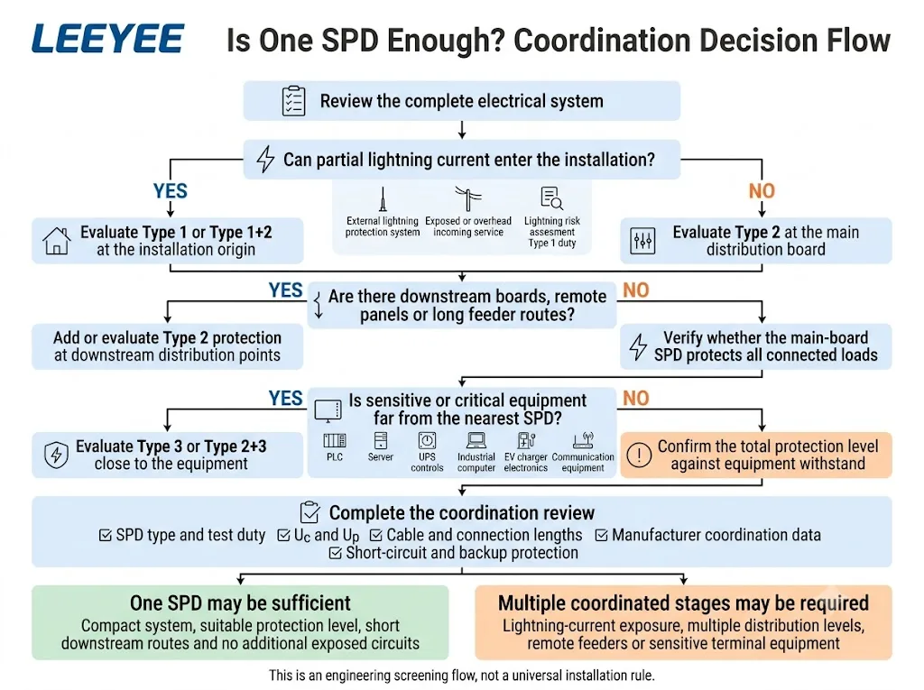
Regra rápida de triagem: se o projeto contiver mais de uma zona de proteção contra descargas atmosféricas, um alimentador remoto ou equipamentos com uma suportabilidade a impulso inferior ao nível efetivo de proteção a montante, avalie uma etapa adicional a jusante.
Onde se encaixam os SPDs do Tipo 1, Tipo 2 e Tipo 3?
As categorias de SPD da IEC correspondem a diferentes ensaios e funções típicas de instalação. O projeto deve atribuir cada dispositivo de acordo com as condições de sobretensão no seu local, em vez de especificar o mesmo SPD para todos os painéis. [2] [5] [6]
| Etapa do SPD | Local típico | Papel principal | Dados críticos do pedido |
|---|---|---|---|
| Tipo 1 | Origem da instalação ou quadro principal de entrada onde se espera a solicitação por corrente de raio | Descarregar corrente parcial de raio usando o ensaio do Tipo 1 | Iimp, corrente total quando aplicável, Uc, Up, polos, modos de proteção e sistema de aterramento |
| Tipo 1+2 | Quadro principal de entrada | Atender aos ensaios do Tipo 1 e do Tipo 2 em um único produto | Ambas as classificações, Iimp, In, Up, proteção de backup e escopo do certificado |
| Tipo 2 | Quadro principal, quadro de subdistribuição, gabinete da máquina ou painel do equipamento | Limitar os surtos de raios induzidos, os surtos residuais a montante e os surtos de manobra | Uc, In, Imax, Up, condições de curto-circuito, polos e modos de proteção |
| Tipo 3 | Perto de equipamentos terminais sensíveis | Garantir a limitação final da tensão após a proteção adequada a montante | Uoc ou regime declarado de Tipo 3, Up, tensão de carga, ponto de instalação e coordenação a montante |
Tipo 1, Tipo 2 e Tipo 3 são funções de engenharia diferentes. Não correspondem a níveis de qualidade de produto baixo, médio e alto.
Como projetar proteção contra surtos coordenada
- Identificar onde a energia dos surtos pode entrar. Rever o sistema externo de proteção contra raios, o trajeto da alimentação de entrada, as linhas aéreas ou subterrâneas, os cabos entre edifícios e a avaliação do risco de raios.
- Marcar todos os níveis de distribuição importantes. Mostrar o quadro principal de baixa tensão, os quadros de subdistribuição, os painéis de UPS, os gabinetes de máquinas, os painéis de inversores, os painéis de carregadores de VE e outras envolventes relevantes no diagrama unifilar.
- Identifique o equipamento crítico e a sua resistência a impulsos. Registe PLCs, servidores, fontes de alimentação de controlo, computadores industriais, inversores, carregadores e outras cargas que possam necessitar de um nível de proteção mais baixo.
- Selecione a função de SPD correta em cada posição. Avalie o Tipo 1 onde existe risco de corrente de raio. Utilize o Tipo 2 para sobretensões residuais, induzidas e de comutação ao nível da distribuição. Avalie o Tipo 3 junto a cargas sensíveis onde é necessária uma proteção de estágio final.
- Verifique o nível de proteção efetivo. Não compare a resistência do equipamento apenas com o valor Up da folha de dados do SPD. Inclua a tensão contribuída pelo esquema de ligação e pelos condutores. [3] [7] [12]
- Verifique a coordenação energética entre os estágios. Confirme se os dispositivos selecionados são testados como uma combinação coordenada, se requerem impedância de condutor ou se necessitam de um componente de desacoplamento externo. [1] [6]
- Verifique as condições de curto-circuito e proteção de reserva. Verifique a corrente de curto-circuito prospetiva, o fusível de reserva ou disjuntor máximo permitido e as instruções de instalação específicas do modelo.
- Reveja todos os serviços condutores. Um SPD de alimentação AC não protege circuitos Ethernet, RS485, 4–20 mA, coaxiais, telefónicos ou outros circuitos de sinal que entrem no mesmo equipamento. [4]
Quando os SPDs do Tipo 1 e Tipo 2 trabalham em conjunto?
A coordenação Tipo 1 e Tipo 2 é avaliada quando a instalação deve gerir tanto o risco de corrente de raio como uma tensão residual mais baixa para a distribuição a jusante ou equipamento.
O estágio Tipo 1 aborda o risco de sobretensão esperado na origem. Um estágio Tipo 2 a jusante limita ainda mais a tensão remanescente e lida com sobretensões de comutação ou induzidas que ocorram após a origem. [5] [6]
| Condição do projeto | Direção da configuração inicial | O que ainda requer confirmação |
|---|---|---|
| São necessários deveres de Tipo 1 e Tipo 2 no mesmo quadro principal | Avalie um SPD combinado Tipo 1+2 | Iimp, In, Up, esquema de ligação à terra, condições de curto-circuito e âmbito do certificado |
| O Tipo 1 está instalado na origem e existe um quadro a jusante separado | Tipo 1 na origem mais Tipo 2 a jusante | Coordenação energética, percurso do cabo, impedância do condutor e requisitos do fabricante |
| Não foi identificado qualquer risco de corrente de raio de Tipo 1 | O Tipo 2 no quadro de distribuição principal pode ser apropriado | Normas nacionais, avaliação de risco, resistência do equipamento e esquema do circuito a jusante |
| Máquina remota, armário exterior ou edifício separado | Proteção a montante mais um Tipo 2 adicional no ponto de distribuição remoto | Exposição do alimentador, ligação equipotencial, ligação à terra, percurso do condutor e entradas de linha de sinal |
O Tipo 1 e o Tipo 2 são estágios complementares. Uma classificação de Tipo 1 não fornece automaticamente o nível de proteção final exigido por cada carga a jusante.
Equipamentos sensíveis precisam de um SPD do Tipo 3?
Nem todos os dispositivos eletrónicos requerem um SPD de Tipo 3 separado. O Tipo 3 deve ser avaliado onde a proteção a montante não demonstre manter uma tensão aceitável nos terminais do equipamento.
O Tipo 3 é normalmente utilizado como estágio final próximo da carga protegida e deve ser coordenado com proteção adequada de Tipo 2 ou Tipo 1+2 a montante. Não substitui a proteção da entrada de serviço ou do quadro de distribuição. [5] [6]
Avalie o Tipo 3 quando
- O equipamento tem um baixo nível de resistência ao impulso.
- A carga é crítica, dispendiosa ou difícil de substituir.
- O equipamento está longe do SPD de distribuição mais próximo.
- O cabo a jusante pode receber sobretensões induzidas adicionais.
- Ocorrem transitórios de comutação locais próximos do equipamento.
- O fabricante do equipamento especifica proteção no ponto de utilização.
Um Tipo 3 separado pode ser desnecessário quando
- Um dispositivo de Tipo 2+3 adequado já está instalado próximo da carga.
- O SPD a montante e o esquema de condutores fornecem um nível de proteção verificado.
- O equipamento possui proteção contra sobretensões integrada documentada.
- O nível de resistência do equipamento é adequado para a tensão residual verificada.
Significado do comprador: solicite a condição de coordenação do Tipo 3, não apenas a folha de dados do Tipo 3. O fornecedor deve identificar o SPD a montante compatível e qualquer requisito de distância ou desacoplamento.
Distância do SPD e coordenação de energia
A distância afeta duas partes diferentes do design de proteção. Estas não devem ser combinadas numa "regra de 10 m" simplificada.
Distância do SPD ao equipamento protegido
Um condutor longo entre um SPD e o equipamento protegido pode receber sobretensões induzidas adicionais. Os condutores também contribuem com tensão durante uma corrente de sobretensão rápida. As orientações baseadas nos princípios de instalação IEC utilizam normalmente cerca de 10 m como ponto em que deve ser considerada uma proteção adicional junto à carga. [3] [7]
Isto não significa que todos os circuitos com mais de 10 m requeiram automaticamente um SPD de Tipo 3. A resistência do equipamento, o percurso do condutor, o ambiente eletromagnético e o nível de proteção a montante eficaz ainda requerem análise.
Distância entre SPDs a montante e a jusante
A impedância do cabo entre os níveis de SPD pode influenciar a forma como a energia do surto é partilhada. No entanto, não existe uma distância de separação universal que garanta a coordenação para todas as combinações de produtos Tipo 1, Tipo 2 e Tipo 3.
Algumas famílias de produtos são testadas para instalação próxima. Certos dispositivos combinados coordenam internamente múltiplas funções de teste. Outras combinações podem exigir impedância de condutor ou um componente de desacoplamento externo. Os dados de coordenação do fabricante aplicáveis devem determinar o arranjo. [1] [6] [11]
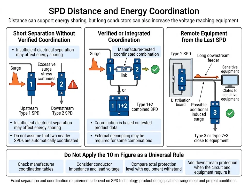
Não especifique "10 m entre cada SPD" como uma condição universal de compra. Questione se os dispositivos propostos são testados como uma combinação coordenada, se é necessária proteção de desacoplamento externa e se é necessária proteção adicional perto de equipamentos remotos.
Os condutores de ligação do SPD são uma questão à parte
Os condutores que ligam cada SPD aos condutores ativos e à terra de proteção devem ser curtos, diretos e instalados de acordo com a norma aplicável e as instruções do fabricante. Um comprimento de ligação excessivo pode aumentar a tensão efetiva que chega ao equipamento protegido. [3] [7]
Consulte o separado guia de instalação de comprimento de ligação do SPD e 0,5 m para considerações detalhadas sobre o comprimento do condutor.
SPD combinado ou etapas de proteção separadas?
Um SPD combinado é testado para mais do que uma função dentro de um único produto. Exemplos comuns incluem dispositivos Tipo 1+2 e Tipo 2+3.
| Configuração | Vantagem principal | Limite que deve ser verificado |
|---|---|---|
| SPD combinado Tipo 1+2 | Fornece ambos os níveis de teste num ponto de instalação e evita a coordenação entre dois produtos separados nessa posição | Não protege automaticamente quadros de distribuição remotos ou equipamentos sensíveis |
| SPDs Tipo 1 e Tipo 2 separados | Permite que os níveis sejam instalados em diferentes níveis de distribuição | A coordenação de energia e qualquer requisito de separação ou desacoplamento devem ser documentados |
| SPD combinado Tipo 2+3 | Pode fornecer funções de distribuição e de nível final perto de equipamentos sensíveis | Um nível de Tipo 1 ou Tipo 2 a montante pode ainda ser necessário, dependendo da exposição do projeto |
Uma classificação combinada descreve as funções testadas de um produto. Não comprova que um edifício inteiro está protegido a partir de um único ponto de instalação.
Exemplo prático: quadro principal, painel da máquina e gabinete do PLC
O que se segue é um exemplo de engenharia ilustrativo. Não é um projeto real de cliente e não especifica classificações de produto obrigatórias.
Esquema do sistema ilustrativo
- Quadro principal de BT: A função Tipo 1 ou Tipo 1+2 deve ser avaliada, uma vez que foi identificada corrente de relâmpago parcial na origem da instalação.
- Painel da máquina: deve ser avaliada a utilização de um SPD Tipo 2 adicional, uma vez que o painel está remoto em relação à origem e pode estar exposto a surtos residuais ou induzidos ao longo do alimentador.
- Armário do PLC: A proteção Tipo 3 ou Tipo 2+3 deve ser avaliada se a proteção efetiva do SPD do painel da máquina não for suficientemente baixa para a fonte de alimentação do PLC e eletrónica ligada.
- Circuitos de sinal: Os condutores Ethernet, RS485 e de sensores que entram no armário do PLC requerem uma análise de interface separada. Os SPDs de potência não protegem estes circuitos.
- Condição de aprovação: os modelos exatos de SPD, valores Up, proteção de reserva e coordenação de energia devem ser confirmados a partir da documentação do fabricante antes da libertação da configuração.
Conclusão de engenharia: as distâncias não provam automaticamente que os três tipos de SPD são obrigatórios. Demonstram por que razão o projetista deve verificar a função de origem, a exposição a surtos a jusante, a resistência do equipamento e a coordenação ao nível do modelo em vez de encomendar um SPD de alta corrente para todo o sistema.
Como avaliar a coordenação de SPD em diferentes projetos
Os exemplos seguintes são orientações de engenharia iniciais. Não são listas de materiais universais. As configurações finais devem seguir o esquema unifilar do projeto, as normas adotadas e as instruções do equipamento.
| Aplicação | Abordagem típica de proteção | Verificações de coordenação adicionais |
|---|---|---|
| Centro de dados | Proteção de origem onde se aplica a função Tipo 1, seguida de Tipo 2 em pontos importantes de UPS, bypass ou distribuição e proteção final onde o equipamento sensível o requer | Alimentações redundantes, modos de funcionamento de UPS, rotas de PDU, distância entre racks, linhas de rede e circuitos de monitorização |
| Sistema de controlo industrial | Proteção do quadro principal seguida de Tipo 2 em máquinas ou armários de controlo; a proteção final pode ser necessária perto de PLCs ou fontes de alimentação sensíveis | Comutação VFD, circuitos de motor, fontes de 24 V CC, sensores, RS485, Ethernet e ligação equipotencial |
| Sistema solar fotovoltaico | Coordene separadamente a proteção de CA e CC fotovoltaica. Utilize SPDs específicos para PV no lado CC e atribua a função Tipo 1 ou Tipo 2 de acordo com o conceito de proteção contra descargas atmosféricas | Tensão fotovoltaica máxima, Ucpv, localização do inversor, trajeto do cabo CC, relação com o SPDA e normas específicas para sistemas fotovoltaicos |
| Projeto de carregamento de VE | Analisar a entrada do local, o quadro de distribuição do carregador e o equipamento de carregamento individual como pontos de proteção separados | Exposição do alimentador exterior, instruções do EVSE, normas nacionais, circuitos de comunicação e IEC 60364-7-722 |
| BESS e PCS | Analisar independentemente a CA do lado da rede, o PCS, a CA auxiliar, a CC do lado da bateria e os circuitos de monitorização | Tensão CC máxima, conceito de ligação à terra, proteção interna do PCS, condições de corrente de defeito e interfaces de comunicação |
Um sistema de SPD de potência coordenado protege apenas os condutores de potência em que está instalado. As interfaces de dados, controlo e comunicação requerem a sua própria análise.
A seleção e coordenação de SPD para FV são especificamente abordadas pelas normas IEC 61643-31 e IEC 61643-32. [9] As instalações de carregamento de VE devem também ser verificadas de acordo com a norma IEC 60364-7-722 e as instruções do fabricante do EVSE. [10]
Como aprovar a combinação real de modelos de SPD
Um artigo geral pode explicar a lógica de coordenação. Não pode provar que dois modelos de SPD específicos estão coordenados energeticamente. A aprovação ao nível do modelo requer evidências específicas do produto.
Esta distinção é importante porque diferentes tecnologias e famílias de produtos podem exigir diferentes distâncias de separação, componentes de desacoplamento ou combinações a montante e a jusante. Uma condição de coordenação publicada para os modelos de um fabricante não deve ser transferida para os produtos de outro fabricante. [11]
| Configuração proposta | Estado da aprovação | Evidência mínima antes da libertação |
|---|---|---|
| Um SPD combinado Tipo 1+2 na origem | Verificação de documentos | Classificação Tipo 1 e Tipo 2 específica do modelo, Iimp, In, Up, Uc, condições de curto-circuito e proteção de reserva |
| SPDs Tipo 1 e Tipo 2 separados da mesma família de produtos | Confirmação de coordenação | Tabela de coordenação do fabricante ou declaração por escrito abrangendo os modelos exatos a montante e a jusante |
| Tipo 2 seguido de Tipo 3 ou Tipo 2+3 | Confirmação de proteção | Compatibilidade a montante, nível de proteção eficaz, condição de distância e resistência do equipamento protegido |
| SPDs de fabricantes diferentes | Avaliação do projeto | Orientação de compatibilidade por escrito, cálculo de engenharia ou validação laboratorial ou de campo adequada |
| SPD alternativo a substituir um modelo de projeto aprovado | Reavaliação completa | Tipo, Uc, Up, classificações de descarga, condições de falha, dimensões, cablagem, âmbito do certificado e dados de coordenação |
Regra de aquisição: nunca deduza a coordenação a partir de etiquetas de Tipo semelhantes, classificações de kA semelhantes ou dimensões externas semelhantes.
Limite profissional: As recomendações de modelos LEEYEE só devem ser emitidas após a revisão das informações exatas do sistema e dos documentos de coordenação aplicáveis. As distâncias de coordenação ou alegações de compatibilidade não verificadas não devem ser adicionadas a uma ficha técnica OEM ou submissão de projeto.
O que os compradores devem confirmar antes de fazer um pedido
Não solicite apenas "um SPD Tipo 1" ou "um SPD Tipo 2". Envie informações suficientes para que o fornecedor analise a cadeia de proteção completa.
Informações do projeto a fornecer
- Diagrama elétrico unifilar;
- Tensão nominal e máxima de funcionamento;
- Aplicação em CA, CC FV, CC de bateria ou sinal;
- TN-S, TN-C-S, TT, IT ou outro esquema de ligação à terra;
- Detalhes do sistema de proteção contra descargas atmosféricas externo;
- Alimentação de entrada e exposição a descargas atmosféricas;
- Localização do quadro principal e quadros a jusante;
- Comprimentos aproximados dos condutores entre quadros e cargas;
- Tipo de SPD necessário ou classificação combinada;
- Requisitos de Uc, Up, Iimp, In, Imax ou Uoc;
- Corrente de curto-circuito prospectiva;
- Detalhes do fusível ou disjuntor a montante;
- Número de polos e modos de proteção;
- Resistência ao impulso do equipamento, quando disponível;
- Normas exigidas e mercados de certificação;
- Requisito de sinalização remota;
- Requisitos de rotulagem e embalagem OEM;
- Quantidade e processo de aprovação de amostras.
Documentos a solicitar ao fornecedor de SPD
- Ficha técnica para cada patamar de SPD proposto;
- Instruções de instalação e esquema de cablagem;
- Tabela de coordenação do fabricante ou declaração de coordenação escrita;
- Distância necessária ou condições de desacoplamento;
- Dados de fusível de reserva ou disjuntor máximo;
- Certificado específico do modelo ou âmbito do relatório de ensaio;
- Dimensões, capacidade do terminal e informações de contacto remoto;
- Plano de validação de amostra para aprovação de OEM ou de projeto.
Misturar marcas requer verificação adicional. As etiquetas de tipo, por si só, não comprovam a coordenação energética. Quando os SPD a montante e a jusante provêm de fabricantes diferentes, obtenha orientação de compatibilidade por escrito ou realize uma avaliação de engenharia específica para o projeto.
Confirmar a configuração completa de SPD
Envie o seu esquema unifilar, tensão do sistema, esquema de ligação à terra, localizações dos quadros, comprimentos dos condutores e normas exigidas para análise técnica.
A LEEYEE fornece apoio à seleção de proteção contra sobretensões e configuração OEM através da CNSPD, a plataforma da LEEYEE focada em proteção contra sobretensões para compradores técnicos globais.
Erros comuns na coordenação de SPD
Escolher apenas pelo maior valor de kA
Iimp, In e Imax representam diferentes deveres de ensaio. Um número maior não corrige o tipo de SPD, Uc, Up, modo de proteção ou posição de instalação incorretos.
Assumir que um SPD de Tipo 1 protege toda a carga a jusante
O Tipo 1 gere o dever de corrente de relâmpago no seu ponto de instalação. Podem ainda ser necessários patamares adicionais de Tipo 2 ou Tipo 3 para atingir o nível de proteção a jusante necessário.
Instalar o Tipo 3 sem proteção a montante adequada
O Tipo 3 é a proteção final do equipamento. Não deve ser selecionado como o dispositivo de proteção principal para a entrada de serviço ou quadro de distribuição principal.
Aplicar a regra dos 10 m a todas as situações
A distância de um SPD ao equipamento e a distância entre dois patamares de SPD são questões diferentes. Dados de coordenação específicos do produto continuam a ser necessários.
Comparar a resistência do equipamento apenas com a ficha técnica Up
O esquema de instalação e os condutores de ligação afetam a tensão efetiva que pode chegar ao equipamento.
Copiar a tabela de coordenação de outro fabricante
Uma distância específica do modelo ou tabela de compatibilidade aplica-se apenas aos produtos e condições indicados. Não pode ser transferida para outra família de SPD sem verificação.
Ignorar o curto-circuito e a proteção de reserva
A coordenação de energia de sobretensão não substitui a verificação da corrente de curto-circuito prevista, da proteção de reserva e dos requisitos de seccionador.
Proteger apenas a linha de alimentação CA
Ethernet, RS485, sensores, circuitos coaxiais e outros circuitos condutores podem contornar o SPD de potência e transportar um transiente para o mesmo equipamento.
Perguntas frequentes sobre coordenação de SPD
Todas as instalações necessitam de SPD de Tipo 1, Tipo 2 e Tipo 3?
Não. Os patamares necessários dependem da exposição à corrente de relâmpago, esquema de distribuição, percursos dos condutores, sensibilidade do equipamento e das regras adotadas para o projeto. Algumas instalações compactas podem usar apenas Tipo 2. Outros projetos podem necessitar de Tipo 1+2 na origem e proteção adicional de Tipo 2 ou Tipo 3 a jusante.
Um SPD de Tipo 1+2 pode substituir dispositivos de Tipo 1 e Tipo 2 separados?
Pode fornecer ambos os deveres de ensaio num único ponto de instalação. Não substitui automaticamente a proteção a jusante para quadros remotos, alimentadores longos ou equipamentos sensíveis.
Os SPD de Tipo 1 e Tipo 2 devem estar sempre separados por 10 metros?
Não. Não existe uma regra universal de separação de 10 m para todas as combinações de SPD. O esquema necessário depende da tecnologia do SPD, dos ensaios do fabricante, da impedância do condutor e se é necessário desacoplamento externo.
O equipamento a mais de 10 metros de um SPD precisa de outro SPD?
A proteção adicional deve ser avaliada, uma vez que condutores longos podem receber sobretensões induzidas e aumentar a tensão efetiva na carga. A decisão final depende do nível de resistência do equipamento, do percurso do condutor, do nível de proteção e das regras de instalação aplicáveis.
O Tipo 3 pode ser instalado sozinho?
O Tipo 3 destina-se a ser uma proteção de estágio final perto de equipamentos sensíveis. Deve ser coordenado com proteção adequada de Tipo 2 ou Tipo 1+2 a montante, em vez de ser utilizado como o SPD principal da instalação.
Podem ser coordenados SPD de diferentes fabricantes?
Podem ser utilizáveis no mesmo projeto, mas a compatibilidade não deve ser assumida a partir das etiquetas de Tipo. Obtenha informações de coordenação por escrito ou realize uma avaliação de engenharia específica para o projeto.
Um SPD incorporado num inversor, UPS ou carregador de VE elimina a necessidade de um SPD externo?
Não automaticamente. Confirme a classificação do SPD interno, potências, modos de proteção, substituibilidade e limites de coordenação com o fabricante do equipamento. A proteção pode ainda ser necessária na origem da instalação ou no quadro de distribuição.
Um SPD de alta corrente pode substituir um sistema de proteção coordenado?
Não necessariamente. Uma classificação de corrente de descarga elevada descreve apenas parte do dever do dispositivo. Não prova que o nível de proteção é suficientemente baixo no equipamento remoto ou que os circuitos a jusante expostos estão cobertos.
Qual é o parâmetro de coordenação de SPD mais importante?
Não existe um parâmetro único. A coordenação correta depende do ciclo de teste do DPS, Uc, Up, condições de compartilhamento de energia, disposição dos condutores, resistência do equipamento, sistema de aterramento, condições de curto-circuito e proteção de retaguarda.
Referências
- Comissão Eletrotécnica Internacional, IEC 61643-12:2020, Dispositivos de proteção contra sobretensões de baixa tensão — Parte 12: Dispositivos de proteção contra sobretensões ligados a sistemas de alimentação de baixa tensão — Princípios de seleção e aplicação. Página de publicação oficial da IEC.
- International Electrotechnical Commission, IEC 61643-01:2024 e IEC 61643-11:2025, Requisitos gerais e métodos de ensaio para dispositivos de proteção contra sobretensões ligados a sistemas de alimentação de baixa tensão em CA. IEC 61643-01; IEC 61643-11.
- Comissão Eletrotécnica Internacional, IEC 60364-5-53:2019+AMD1:2020+AMD2:2024, Instalações elétricas de baixa tensão — Parte 5-53: Seleção e instalação de equipamento elétrico. Página oficial da publicação consolidada da IEC.
- Comissão Eletrotécnica Internacional, IEC 62305-4:2024, Proteção contra descargas atmosféricas — Parte 4: Sistemas elétricos e eletrónicos em estruturas. Página de publicação oficial da IEC.
- Instituição de Engenharia e Tecnologia, Dispositivos de proteção contra sobretensões (DPS). Orientação técnica que abrange tipos de SPD, locais típicos e proteção coordenada. Artigo técnico da IET.
- Phoenix Contact, Fundamentos para proteção contra surtos. Orientação sobre zonas de proteção contra descargas atmosféricas, posições de aplicação de Tipo 1, Tipo 2 e Tipo 3 e conceitos de proteção coordenada. Guia técnico oficial.
- DEHN, Proteção contra surtos em conjuntos de manobra de baixa tensão. Orientação sobre nível de proteção eficaz, comprimento do condutor e proteção coordenada a jusante. Documento técnico oficial.
- BEAMA, Guia para Dispositivos de Proteção contra Sobretensões: Seleção, Aplicação e Teoria. Página de recursos da BEAMA.
- International Electrotechnical Commission, IEC 61643-31:2018 e IEC 61643-32:2017, Dispositivos de proteção contra sobretensões para instalações fotovoltaicas — Requisitos, seleção e princípios de aplicação. IEC 61643-31; IEC 61643-32.
- Comissão Eletrotécnica Internacional, IEC 60364-7-722:2018, Instalações elétricas de baixa tensão — Requisitos para alimentação de veículos elétricos. Página de publicação oficial da IEC.
- Schneider Electric, CA903014E, Versão 2.7, 2025, Coordenação de Dispositivos de Proteção contra Sobretensões para Edifícios Comerciais e Industriais. Cronogramas de coordenação específicos do produto que ilustram que as condições de coordenação dependem da combinação exata de dispositivos. Página de documento oficial da Schneider Electric.
- Comissão Eletrotécnica Internacional, IEC 60664-1:2020+AMD1:2025, Coordenação de isolamento para equipamentos em sistemas de alimentação de baixa tensão — Parte 1: Princípios, requisitos e ensaios. Página oficial da publicação consolidada da IEC.
Este artigo fornece orientação geral de engenharia e aprovisionamento. A disposição final dos SPD deve ser confirmada de acordo com as normas e regras nacionais adotadas para o projeto, a avaliação de risco de descargas atmosféricas e sobretensões, o diagrama unifilar elétrico, as instruções do fabricante do equipamento e a documentação de coordenação de SPD específica do modelo. Não deve ser assumida nenhuma distância de coordenação, compatibilidade de modelo ou âmbito de certificado sem verificação.
