
Der Überspannungsschutz von Kommunikationsmasten muss den gesamten Funkturm abdecken, nicht nur ein SPD in einem Außengehäuse. Das gleiche standortbezogene Prinzip gilt für den Überspannungsschutz von Mobilfunkstandorten, den Blitzschutz von Telekommasten und viele Installationen von Funkbasisstationen.
Die Turmkonstruktion, AC-Versorgung, -48 V DC-Zuführungen, Antennenanschlüsse, Kupferdatenleitungen, Gerätegehäuse und das Erdungssystem des Standorts müssen als ein koordiniertes Schutzsystem arbeiten.
Inhaltsübersicht
Schnelle Antwort
Ein Standort für Kommunikationsmasten benötigt normalerweise vier koordinierte Funktionen: ein externes Blitzschutzsystem, ein Erdungssystem für den Standort, gleichwertige Bonding und korrekt ausgewählte SPDs für leitfähige Strom- und Signalleitungen.[1][2]
AC-Strom, -48 V DC, RF- oder koaxiale Zuführungen, Ethernet, PoE und Steuerleitungen erfordern verschiedene Schutzgeräte. Jedes SPD muss mit dem tatsächlichen Schaltkreis, der Installationsgrenze und der erwarteten Überspannungsexposition übereinstimmen.
Bedeutung für Käufer: Senden Sie dem Anbieter die Standortarchitektur, Betriebsspannungen, Erdungsanordnung, Kabelschnittstellen und vorgeschlagenen SPD-Positionen. Eine Anfrage nur nach “einem SPD für einen Kommunikationsmast” ist nicht ausreichend für eine zuverlässige Auswahl.
Wie Blitzschutz und Überspannungsschutz für Kommunikationsmasten zusammenarbeiten
Ein direkter Blitzschlag kann Strom durch die Turmstruktur, das Erdnetsystem, Kabelabschirmungen und angeschlossene Dienste leiten. Elektronische Geräte können daher beschädigt werden, selbst wenn der Blitz nicht direkt einen Geräteanschluss trifft.
ITU-T K.112 bietet praktische Verfahren zum Blitzschutz, zur Erdung und zum Verbinden an eigenständigen und Dachfunkbasisstationen.[2] ITU-T K.119 bewertet vier verbundene Teile des Schutzsystems.[3]
Lufteintritt und Stromweg
Das externe System fängt direkten Blitz ein und bietet einen vorhergesehenen Weg zur Erde.
Standorterdesystem
Der Turm, der Schutzraum und die zugehörigen Strukturen sind mit einem koordinierten Erdungsnetzwerk verbunden.
Gleichpotentialverbindung
Metallstrukturen, Kabelabschirmungen, Gerätegestelle und Schutzleiter sind koordiniert, um potenzielle Unterschiede zu begrenzen.
Überspannungsschutzsgeräte
SPDs begrenzen geleitete Überspannungen auf AC-, DC-, RF-, Daten- und Steuerkreisen an den relevanten Grenzen.
Was umfasst eine vollständige Architektur zum Schutz von Turmstandorten?
Beginnen Sie mit dem physischen Standort und nicht mit einem Produktkatalog. Verfolgen Sie die erwarteten Blitzstromwege, identifizieren Sie jedes leitfähige Kabel, das eine Schutzgrenze überschreitet, und weisen Sie der jeweiligen Stelle die richtige Schutzfunktion zu.
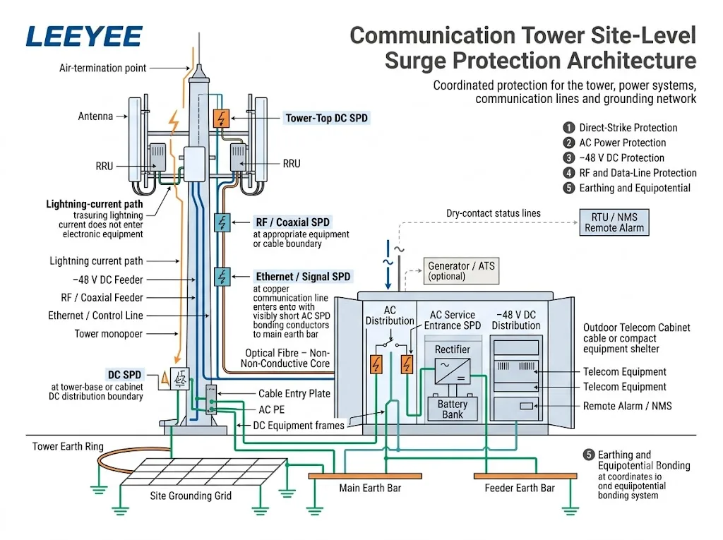
- Bewerten Sie den Turm und seine Blitzexposition. Bestätigen Sie, ob die Installation ein eigenständiger Turm, eine Dachstandorte, ein Monopol, ein Rundfunkmast oder eine Remote-Wireless-Station ist. IEC 62305-2 bietet ein Risikomanagementverfahren zur Auswahl geeigneter Schutzmaßnahmen.[5]
- Definieren Sie das äußere Blitzschutzsystem. Bestätigen Sie die Luftableitungsanordnung, den Strompfad, die Erdableitung, die Trennanforderungen sowie den Schutz gegen Berührungs- und Schrittspannungen.[6]
- Etablieren Sie das Erdungskonzept für den Standort. Identifizieren Sie die Turm-Stahlkonstruktion, das Gehäuse, den Schutzraum, die Kabeldurchführungsplatte, die Erdungsleisten, AC PE, DC-Gerätrahmen und Radioequipment-Racks.
- Kartieren Sie jeden elektrischen Dienst. Schließen Sie Versorgungs-AC, Generatoren, −48 V DC, koaxiale Zu- und Abgänge, Ethernet, PoE, RS485, AISG, Alarmleitungen, Sensoren und Turmbeleuchtungsstromkreise ein.
- Markieren Sie jede Schutzgrenze. Identifizieren Sie, wo Kabel einen potentialfreien Bereich betreten oder verlassen und wo empfindliche Geräte angeschlossen sind.
- Wählen und koordinieren Sie die Überspannungsschutzgeräte (SPDs). Verwenden Sie die anwendbare Norm für AC-, DC- oder Telekommunikations-SPD und prüfen Sie die an jedem Standort erforderlichen Parameter.[8][9][11][12]
- Planen Sie die Inbetriebnahme und Wartung. Halten Sie Anzeigen, Fernkontakte, Erdungspunkte und austauschbare Module für Inspektionen zugänglich.
Wo können Überspannungen in einen Kommunikationsmaststandort eindringen?
Der Mast ist der sichtbarste Expositionspunkt, aber er ist nicht der einzige Weg. Jede leitfähige Verbindung zwischen Außenanlagen, dem Mast, der Stromquelle, dem Schrank und empfindlicher Elektronik erfordert eine Prüfung.
| Eintrittsweg | Typische Exposition | Schutzfunktion | Der Käufer muss bestätigen |
|---|---|---|---|
| Mast oder Antennenturm | Direkter Blitzeinschlag und Blitzstromfluss durch die Konstruktion | Äußeres LPS, Strompfad, Erder und Erdung | Masttyp, Höhe, Anordnung, Risikobewertung und LPS-Design |
| AC-Versorgung | Versorgungsleitung, Freileitungsabschnitt, Generator, ATS oder Standortverteilung | AC-SPD abgestimmt auf die Versorgung und die Blitzeinwirkung | Spannung, Phasen, Erdungssystem, Uc, Iimp oder In, Up und Backup-Schutz |
| −48 V DC-Zuleitung | Lange Kupferzuleitung zwischen Gleichrichter, DC-Verteilung und mastmontiertem Funkgerät | Niederspannungs-DC-SPD an den erforderlichen Schutzgrenzen | Maximale Busspannung, Polarität, Erdung, Schutzmodi und SPD-Positionen |
| RF- oder Koaxialleitung | Metallischer Antennenzuführer, Steckverbinder und Kabelschirm | RF-Überspannungsschutzgerät und Schirmanbindung an der vorgesehenen Grenze | Steckverbinder, Impedanz, Frequenz, HF-Leistung, Einfügungsdämpfung und VSWR |
| Ethernet oder PoE | Outdoor-Kupfernetzwerkkabel zwischen verschiedenen Gerätebereichen | Datenleitungs-Überspannungsschutzgerät, abgestimmt auf Ethernet- und PoE-Leistung | Datenrate, PoE-Typ, Leistung, geschützte Adernpaare und Schirmung |
| Steuer- oder Alarmleitung | RS485-, AISG-, Sensor-, potentialfreie Kontakt- oder Navigationslicht-Schaltung | Signal-Überspannungsschutzgerät, ausgewählt für den tatsächlichen Betriebskreis | Spannung, Protokoll, Adernpaaranzahl, Strom und Klemmenanordnung |
Ein rein dielektrisches Glasfaserkabel leitet keinen Stoßstrom durch die Glasfaser. Metallische Armierungen, Zugelemente, Hybrid-Leistungsleiter, Gerätegehäuse und zugehörige Kupferschaltungen müssen dennoch bewertet werden.
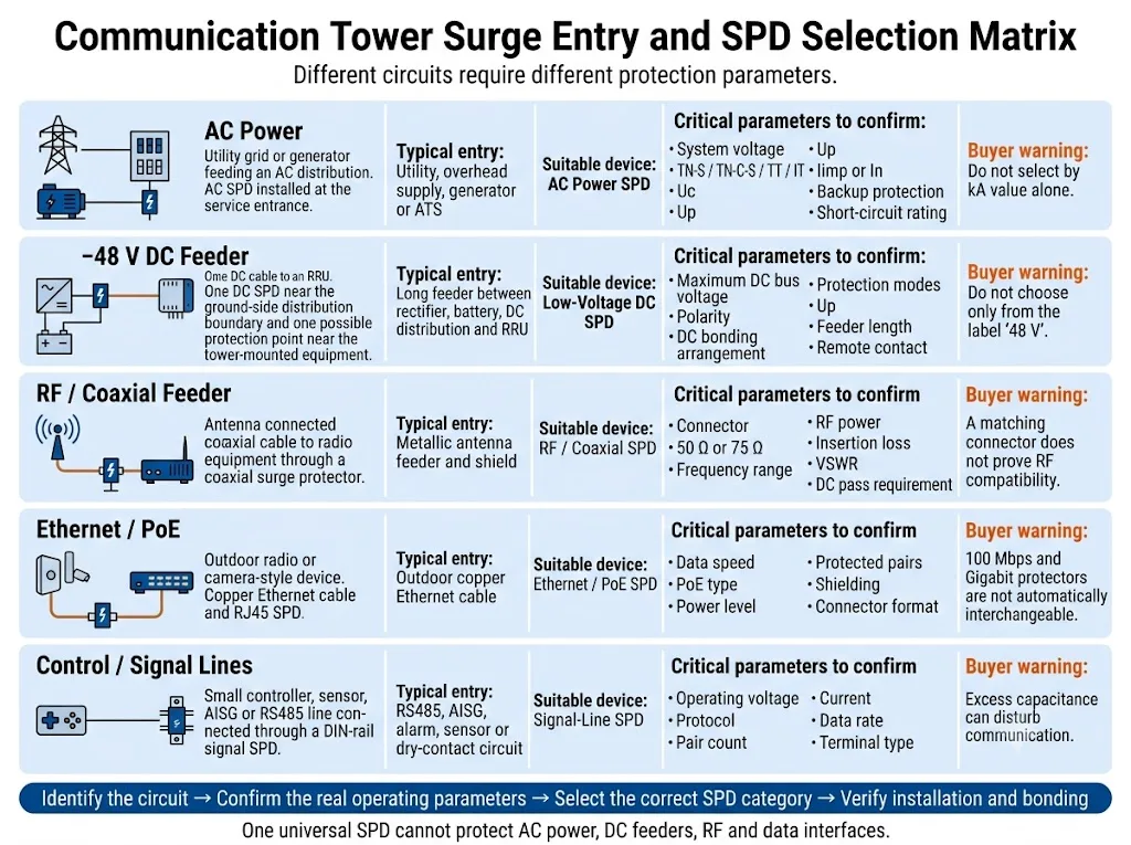
Einkaufsfazit: identifizieren Sie den Stromkreis, bevor Sie die Bemessungswerte für den Ableitstrom vergleichen. Ein hoher kA-Wert oder ein passender Steckverbinder belegt nicht die Kompatibilität mit der Betriebsspannung, dem Schutzmodus, der Frequenz oder der Datenleistung.
Wie sollte der AC-Eingang geschützt werden?
Die AC-Schutzanordnung hängt von der Exposition des Masts, der einspeisenden Versorgung, dem externen Blitzschutzsystem und der vorgeschalteten Verteilung ab.
Ein freistehender Mast mit exponierter Einspeisung kann eine andere Lösung erfordern als Dachanlagen, die über ein geschütztes Gebäudeverteilungssystem versorgt werden.
IEC 61643-11:2025 legt Anforderungen und Prüfverfahren für SPDs fest, die an AC-Niederspannungsversorgungssysteme angeschlossen sind.[9] IEC 61643-12:2020 behandelt Auswahl, Betrieb, Einbauort und Koordination von AC-SPDs.[10]
Bestätigen Sie diese AC-Parameter
- Systemspannung und Uc: Verwenden Sie die tatsächliche maximale Dauerbetriebsspannung, nicht nur die nominale Netzbezeichnung.
- Erdungssystem: TN-S-, TN-C-S-, TT- und IT-Anordnungen können unterschiedliche Schutzmodi erfordern.
- Blitzstrom-Belastung: bestätigen Sie, ob Typ 1, Typ 1+2 oder eine andere abgestimmte Anordnung erforderlich ist.
- Spannungsschutzpegel: stimmen Sie Up mit der Festigkeit des Betriebsmittels und dem nachgeschalteten Schutz ab.
- Ableitparameter: bestätigen Sie Iimp, In oder Imax gemäß der SPD-Klassifizierung und den Projektanforderungen.
- Kurzschlussbedingungen: prüfen Sie den zu erwartenden Kurzschlussstrom, die Kurzschlussfestigkeit des SPD und den Back-up-Schutz.
- Alternative Strompfade: Umfasst Generatoren, ATS-Schaltkreise und alle weiteren angeschlossenen Quellen.
- Verbindungspfad: Halten Sie die vollständige SPD-Verbindung kurz und direkt, da die Leiterinduktivität bei einem schnellen Stoßstrom die Spannung erhöht.
Wie sollte das -48 V DC-Zuführungskabel geschützt werden?
Funkstandorte verwenden häufig Gleichrichter und Batterien, um am Mast montierte Funkanlagen über lange DC-Kupferleitungen zu versorgen. Ein Transientenimpuls kann von der Mastseite eindringen oder durch einen Potenzialunterschied zwischen der Mastanlage und den bodennahen Geräten entstehen.
IEC 61643-41:2025 gilt für SPDs, die an Gleichstromkreise und Geräte mit einer Nennspannung von bis zu 1.500 V DC angeschlossen sind.[11] Das ausgewählte Gerät muss dennoch für den tatsächlichen Niederspannungs-Telekommunikationsstromkreis ausgelegt und spezifiziert sein.
Wählen Sie nicht allein anhand der Kennzeichnung „48 V“ aus.
Der Gleichspannungszwischenkreis kann während des Gleichrichterbetriebs, des Batterieladevorgangs oder der Systemanpassung über seinen Nennwert ansteigen. Bestätigen Sie die höchste dauerhafte Betriebsspannung, bevor Sie die Nennspannung des SPD festlegen.
| Frage zum Gleichstrom | Warum es wichtig ist | Bereitzustellende Informationen |
|---|---|---|
| Maximale Zwischenkreisspannung | Eine ungeeignete Dauerspannung kann zu vorzeitiger Alterung oder einem unangemessenen Schutzniveau führen. | Gleichrichterbereich, Erhaltungsladespannung der Batterie, Ladespannung und Grenzwerte für den anormalen Betrieb. |
| Gleichstrom-Potentialausgleichsanordnung | Schutzmodi hängen von der Beziehung zwischen DC+, Rückleitung, DC− und PE ab. | Einpoliger Schaltplan sowie die projektbezogene Potentialausgleichs- oder Erdungsanordnung. |
| Exponierung der Einspeiseleitung | Eine lange Einspeiseleitung, die verschiedene Anlagenbereiche durchquert, kann einen koordinierten Schutz an mehr als einer Schnittstelle erfordern. | Leitungslänge, Leitungsführung, Mast-Höhe, Funkstandorte und vorgesehene Positionen der Überspannungsschutzgeräte (SPD). |
| Statusüberwachung | Eine Störung an einem unbemannten Standort kann ohne Fernsignal unbemerkt bleiben. | Erforderlich sind ein Schließer-, Öffner- oder Wechslerkontakt sowie die Alarm-Logik der RTU oder des NMS. |
Wie sollten RF-, Ethernet- und Steuerleitungen geschützt werden?
Jeder Schutzleiter muss die normale Funktion seines Stromkreises aufrechterhalten und gleichzeitig transiente Spannungen begrenzen. Ein Gerät kann mechanisch passen und dennoch elektrisch ungeeignet sein.
HF- und Koaxial-Speiseleitungen
Bestätigen Sie den Steckertyp, den charakteristischen Wellenwiderstand, die Betriebsfrequenz, die HF-Leistung, die Einfügungsdämpfung, die Rückflussdämpfung bzw. das VSWR, die Anforderungen an die DC-Durchleitung sowie die Umgebungsbedingungen.
Die Kabelabschirmung und der HF-Schutz sollten an der vom Standortdesign geforderten Stelle geerdet werden. Ein Schutz oder eine Erdung an beiden Enden kann bei einigen Architekturen sinnvoll sein, ist jedoch keine allgemeingültige Regel.
Ethernet und PoE
IEC 61643-21:2025 behandelt Überspannungsschutzgeräte (SPDs) für Telekommunikations- und Signalnetzwerke, einschließlich Netzwerken, die Strom über dieselbe Leitung übertragen, wie beispielsweise PoE.[12]
Überprüfen Sie die Ethernet-Geschwindigkeit, den PoE-Typ, die maximale Leistung, die geschützten Adernpaare, die Schirmung sowie die zulässige Einfügungsdämpfung. Ein Gerät, das für 100 Mbit/s oder PoE mit geringer Leistung ausgelegt ist, sollte nicht automatisch als geeignet für Gigabit-Ethernet oder PoE mit höherer Leistung angesehen werden.
RS485-, AISG-, Alarm- und Sensorschaltkreise
Stimmen Sie den Überspannungsschutz (SPD) auf die Betriebsspannung, den maximalen Signalpegel, die Anzahl der Leiter, die Stromstärke, die Datenrate, den Referenzleiter und die Anschlussbelegung ab.
Eine zu hohe Kapazität oder ein ungeeignetes Schutzniveau können die Kommunikation stören, selbst wenn der Überspannungsschutz selbst noch betriebsbereit ist.
Warum bestimmen Erdung und gleichwertige Bonding den Ausgang?
Ein SPD leitet Stoßströme in das Potenzialausgleichs- und Erdungsnetzwerk ab. Wenn dieser Pfad lang, indirekt, korrodiert oder schlecht koordiniert ist, kann die Spannung am geschützten Gerät deutlich höher sein als der im Datenblatt des SPD angegebene Up-Wert.
Der Standortpotenzialausgleich ist nicht einfach nur eine Ansammlung von Erdungsstäben. Sein Zweck besteht darin, gefährliche Potenzialunterschiede zwischen Mast, Schaltschrank, Schutzgehäuse, Kabelschirmen, AC-PE, DC-Geräten und anderen leitfähigen Systemen während eines Blitzeinschlags zu reduzieren.[2][7]
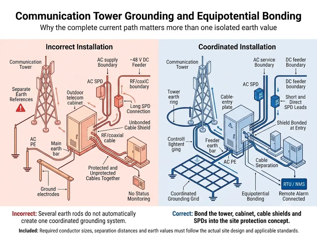
Ein einzelner Erdungswiderstandswert ist keine vollständige Lösung.
Der Erdungswiderstand ist wichtig, das Ergebnis hängt jedoch auch von Leitungsführung, Induktivität, Netzgeometrie, Bodenbeschaffenheit, Stromaufteilung, Verbindungsqualität, Korrosion und der Position des Potenzialausgleichs ab.
Versprechen Sie nicht, dass jeder Mast geschützt ist, nur weil der gemessene Widerstand unter einem festen Wert liegt. Abnahmekriterien müssen den Standortspezifikationen, lokalen Vorschriften, der Messmethode und einer qualifizierten Blitzschutzplanung entsprechen.
Potenzialausgleichspunkte, die üblicherweise eine Überprüfung erfordern
- Stahlkonstruktionen von Türmen, Monopole oder Mastfüße.
- Externe Ableitungen, sofern diese separat installiert wurden.
- Erdungsschiene am Mastfuß und Haupterdungsschiene im Betriebsraum.
- Rahmen des Außenschranks, Tür, Kabeleinführungsplatte und interne PE-Schiene.
- Koaxialkabelschirmungen und Erdungsschienen für Speiseleitungen.
- AC-PE, Erdung des Generators und ATS-bezogene Potenzialausgleichsverbindungen.
- Gleichrichter, Batterierack, Gleichstromverteilung und Telekommunikationsschränke.
- Metallische Kabeltrassen, Zäune und zusätzliche Mastausrüstung gemäß den Anforderungen des Entwurfs.
Warum ist die Grenze zwischen Turm und Schrank kritisch?
Der Punkt, an dem Kabel den Turm verlassen und in einen Außenschrank oder ein Schutzgehäuse eintreten, vereint freiliegende Leiter, Kabelschirme, Erdungsverbindungen und empfindliche elektronische Anschlüsse.
- Platzieren Sie den geeigneten Überspannungsschutz (SPD) in der Nähe des jeweiligen Kabeleintritts oder der Anlagengrenze.
- Verbinden Sie die Kabelschirme an der Erdungsschiene der Zuleitung oder an dem laut Standortplanung definierten Eintrittspunkt.
- Verwenden Sie kurze, direkte Erdungsleiter für den Überspannungsschutz.
- Trennen Sie geschützte und ungeschützte Kabelabschnitte, um eine erneute Einkopplung von Überspannungen zu reduzieren.
- Vermeiden Sie unnötige Schleifen, scharfe Leitungsführungen und übermäßige Leitungslängen.
- Integrieren Sie den Mast, den Schaltschrank und das Schutzgehäuse in das koordinierte Erdungssystem des Standorts.
- Halten Sie Anzeigen, austauschbare Module und abgesetzte Terminals nach der Installation zugänglich.
Wie sollten entfernte Alarme und Wartung geplant werden?
Viele Funktürme befinden sich an abgelegenen oder unbemannten Standorten. Ein defektes Modul, ein gelöster Potenzialausgleichsleiter oder eine korrodierte Verbindung können bis zum nächsten Überspannungsereignis unbemerkt bleiben.
ITU-T K.119 behandelt Sichtprüfungen, Messungen, Analysen sowie weitere Methoden zur Bewertung der Zuverlässigkeit von Blitzschutz- und Erdungssystemen an Funkbasisstationen.[3] IEC 62305-4 umfasst zudem die Inspektion, Wartung und Prüfung von Blitzschutzmaßnahmen.[7]
Die Fernüberwachung kann Folgendes melden:
- Den Status eines normalen oder defekten SPD-Moduls.
- Das Entfernen von Modulen, sofern der SPD-Mechanismus dies unterstützt.
- Schließer-, Öffner- oder Wechsler-Kontaktzustand (potenzialfrei).
- Ein Alarmeingang für eine RTU, SPS, Schranksteuerung oder ein Netzwerkmanagementsystem.
Die Fernanzeige unterstützt die Wartung, ersetzt jedoch keine physische Inspektion. Korrosion, lose Leiter, Gehäuseschäden und falsch eingesetzte Ersatzmodule werden durch einen Hilfskontakt möglicherweise nicht erkannt.
Überprüfen Sie das Schutzsystem.
- Während der Erstinbetriebnahme und Abnahme.
- Zum geplanten Intervall für die vorbeugende Wartung.
- Nach einem protokollierten Blitzeinschlag oder einer ungeklärten Gerätestörung.
- Nach dem Hinzufügen von Antennen, Funkgeräten, Stromversorgungsanlagen oder einem weiteren Schaltschrank.
- Nach Erdungsarbeiten, Tiefbauarbeiten oder Änderungen an der Kabelführung.
- Wenn ein SPD-Indikator oder ein Fernalarm seinen Zustand ändert.
Wie beeinflusst der Standorttyp die Schutzentscheidung?
Eigenständiger Erdmast
Dieser Standort verfügt normalerweise über einen eigenen Mast, ein Erdungsnetz, eine Strom- oder Generatorversorgung, ein Gerätegehäuse und mehrere freiliegende Kupferleiter. Er kann einen direkten Blitzschutz sowie koordinierte AC-, DC-, HF- und Signalleitungs-Überspannungsschutzgeräte (SPDs) erfordern.
Dachmontage von Funkanlagen
Die auf dem Dach installierten Geräte nutzen das Blitzschutzsystem, die Haupterdungsschiene und die Stromverteilung des Gebäudes. Der Planer muss den Trennungsabstand, die Schutzzonen und die Abstimmung mit den vorhandenen Überspannungsschutzgeräten (SPD) des Gebäudes überprüfen.
Abgesetzter Richtfunk- oder Überwachungsstandort
Dieser Standort kann Batterien, Solarenergie, eine kleine Wechselstromquelle, lange Ethernet- oder Steuerleitungen sowie einen eingeschränkten Wartungszugang erfordern. Die Auswahl muss auf den tatsächlichen leitungsgebundenen Schnittstellen und der Stromversorgungsarchitektur basieren.
Ingenieurtechnische Schlussfolgerung: „Kommunikationsturm“ bezeichnet kein universelles SPD-Paket. Der physische Standort und die Kabelarchitektur bestimmen, welche Schutzfunktionen erforderlich sind.
Wie sollte ein Käufer das vorgeschlagene SPD-Paket überprüfen?
Diagramme erläutern das Schutzkonzept, stellen jedoch keine Produktzulassungen dar. Überprüfen Sie vor der Freigabe eines Turmstandort-Pakets jedes vorgeschlagene Modell anhand des zu schützenden Stromkreises.
Modellspezifische Nachweise anfordern
LEEYEE ist ein spezialisierter Anbieter von Überspannungs- und Niederspannungsschutzlösungen. CNSPD ist die auf Überspannungsschutz ausgerichtete Plattform von LEEYEE für technische Einkäufer weltweit.
Ein Zertifikat für eine Serie oder Konfiguration darf nicht automatisch als Zulassung für jede Spannung, Polanordnung, jeden Steckverbinder oder jede OEM-Variante betrachtet werden. Bestätigen Sie den exakten Dokumentenumfang vor der Projekteinreichung.
Was sollte vor der Bestellung bestätigt werden?
Halten Sie die folgenden Informationen bereit, bevor Sie Modellvorschläge, Muster, technische Unterlagen oder ein OEM-Angebot anfordern.
Fordern Sie eine Überprüfung der Kommunikationsmast-SPD-Konfiguration an
Stellen Sie LEEYEE das einpolige Netzdiagramm, den Turm- und Schrankaufbau, Details zur AC-Versorgung, die maximale DC-Busspannung, Kabelschnittstellen sowie die Erdungszeichnung zur Verfügung.
Vorgeschlagene Modelle und Installationspositionen müssen anhand der tatsächlichen Geräteanweisungen, der örtlichen Elektrovorschriften, der Projektspezifikationen und eines qualifizierten Blitzschutzkonzepts bestätigt werden.
Häufig gestellte Fragen zum Überspannungsschutz von Kommunikationsmasten
Kann ein einzelner AC-Überspannungsschutz (SPD) den gesamten Standort eines Kommunikationsturms absichern?
Erfordert jeder Kommunikationsturm einen Typ-1-Überspannungsschutz?
Wo sollte der −48 V DC-SPD installiert werden?
Kann ein PV-DC-Überspannungsschutzgerät für ein 48-V-Telekommunikationssystem verwendet werden?
Macht die Verwendung von Glasfaserkabeln einen Überspannungsschutz überflüssig?
Sollte an beiden Kabelenden ein HF-Überspannungsschutz installiert werden?
Reicht ein niedriger Erdungswiderstandswert aus?
Ist eine Fernalarmierung an einem Funkmaststandort sinnvoll?
Welche Dokumente sollte ein OEM-Käufer anfordern?
Referenzen
- Internationale Fernmeldeunion, ITU-T K.56 (05/2021), Schutz von Funkbasisstationen vor Blitzeinschlägen. Offizielle ITU-Publikation.
- Internationale Fernmeldeunion, ITU-T K.112 (05/2021), Blitzschutz, Erdung und Potenzialausgleich: Praktische Verfahren für Funkbasisstationen. Offizielle ITU-Publikation.
- Internationale Fernmeldeunion, ITU-T K.119 (12/2016), Konformitätsbewertung von Funkbasisstationen hinsichtlich Blitzschutz und Erdung. Offizielle ITU-Publikation.
- Internationale Elektrotechnische Kommission, IEC 62305-1:2024, Blitzschutz – Teil 1: Allgemeine Grundsätze. Offizielle IEC-Publikation.
- Internationale Elektrotechnische Kommission, IEC 62305-2:2024, Blitzschutz – Teil 2: Risikomanagement. Offizielle IEC-Publikation.
- Internationale Elektrotechnische Kommission, IEC 62305-3:2024, Blitzschutz – Teil 3: Schutz von baulichen Anlagen und Personen. Offizielle IEC-Publikation.
- Internationale Elektrotechnische Kommission, IEC 62305-4:2024, Blitzschutz – Teil 4: Elektrische und elektronische Systeme in baulichen Anlagen. Offizielle IEC-Publikation.
- Internationale Elektrotechnische Kommission, IEC 61643-01:2024, Überspannungsschutzgeräte für Niederspannung – Teil 01: Allgemeine Anforderungen und Prüfverfahren. Offizielle IEC-Publikation.
- Internationale Elektrotechnische Kommission, IEC 61643-11:2025, Überspannungsschutzgeräte für Niederspannung – Teil 11: Überspannungsschutzgeräte für den Einsatz in Niederspannungsanlagen – Anforderungen und Prüfungen. Offizielle IEC-Publikation.
- Internationale Elektrotechnische Kommission, IEC 61643-12:2020, Überspannungsschutzgeräte für Niederspannung – Teil 12: Überspannungsschutzgeräte für den Einsatz in Niederspannungsanlagen – Auswahl- und Anwendungsprinzipien. Offizielle IEC-Publikation.
- Internationale Elektrotechnische Kommission, IEC 61643-41:2025, Überspannungsschutzgeräte für Niederspannung – Teil 41: Überspannungsschutzgeräte für den Einsatz in Gleichstrom-Niederspannungsnetzen – Anforderungen und Prüfverfahren. Offizielle IEC-Publikation.
- Internationale Elektrotechnische Kommission, IEC 61643-21:2025, Überspannungsschutzgeräte für Niederspannung – Teil 21: Überspannungsschutzgeräte für den Einsatz in Telekommunikations- und signalverarbeitenden Netzwerken – Anforderungen und Prüfverfahren. Offizielle IEC-Publikation.
- Internationale Elektrotechnische Kommission, IEC 61643-31:2018, Überspannungsschutzgeräte für Niederspannung – Teil 31: Anforderungen und Prüfverfahren für Überspannungsschutzgeräte für den Einsatz in Photovoltaikanlagen. Offizielle IEC-Publikation.
