
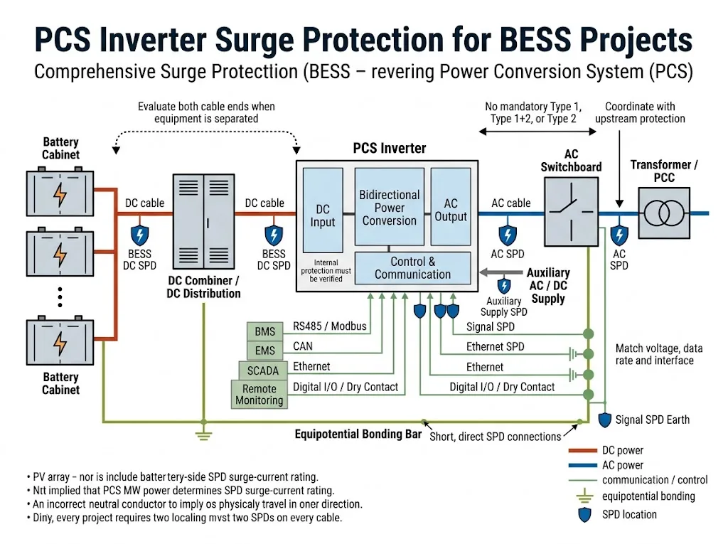
Ein BESS-Leistungswandlungssystem verbindet den DC-Kreis auf der Batterieseite mit einem AC-Schaltschrank, Transformator, Netz oder lokaler Last. Dasselbe PCS kann auch mit einem BMS, EMS, SCADA-Plattform, Hilfsversorgung und mehreren Kommunikationsnetzen verbunden werden.
Jede leitfähige Schnittstelle kann ein Eingangspfad für Überspannungen werden. Daher sollte der Überspannungsschutz des PCS-Wechselrichters als ein Koordinationsproblem der Schnittstellen betrachtet werden - nicht als eine Anfrage nach einem generischen SPD, der nur aus der PCS-Leistung oder Nennspannung ausgewählt wurde.
Inhaltsübersicht
Braucht ein PCS-Wechselrichter in einem BESS Überspannungsschutz?
Die AC-, Batterie-DC-, Kommunikations- und Hilfsanschlüsse eines BESS-PCS sollten jeweils auf koordinierten Überspannungsschutz bewertet werden.
Die endgültige Anordnung hängt vom PCS-Handbuch, maximalen Betriebsströmen, Erdungs- und Erdungsanordnungen, möglichem Fehlerstrom, Kabelverlegung, Blitzeinwirkung, internem PCS-Schutz und Projektspezifikation ab.[1][2]
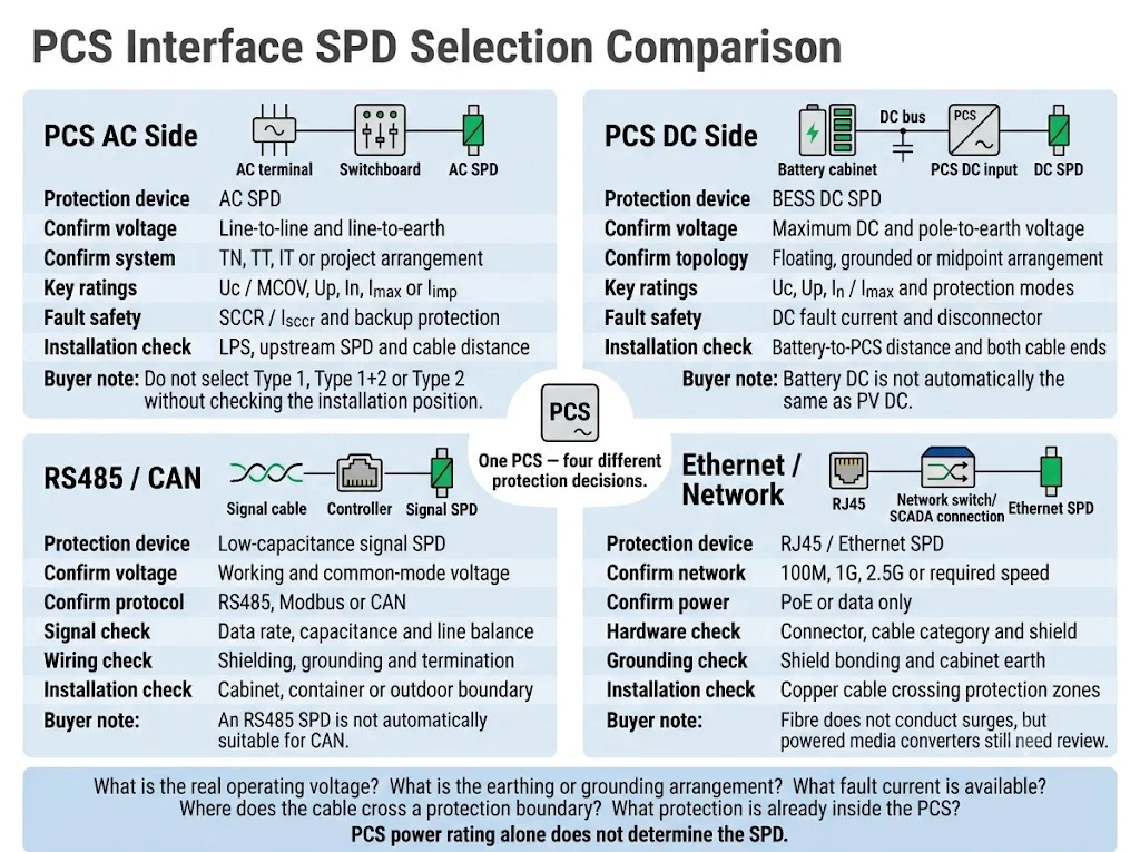
| PCS-Schnittstelle | Schutzrichtung | Hauptbestätigung |
|---|---|---|
| DC-Eingang | BESS DC SPD ausgewählt für den tatsächlichen Batterieseitenschaltkreis | Maximale DC-Spannung, Pol-zu-Erde-Spannung, Erdungstopologie und Fehlerstrom |
| AC-Anschluss | Koordinierter AC SPD an der relevanten PCS- oder Schalttafelgrenze | AC-Spannung, Erdungssystem, LPS, vorgelagerter SPD und Installationsposition |
| RS485 / CAN | Signal SPD abgestimmt auf den Kreis | Arbeits- spannung, Datenrate, Kapazität, Abschirmung und Erdung |
| Ethernet | Netzwerk SPD, wo Kupferkabel eine Schutzgrenze überschreiten | Netzgeschwindigkeit, PoE-Status, Anschluss, Kabelkategorie und Schirmverbindung |
| Hilfsversorgung | AC- oder DC-SPD gemäß dem tatsächlichen Hilfskreis | Versorgungs- spannung, Quelle, Kabelbelastung und Ausrüstungsschutzlevel |
Bedeutung für Käufer: “1 MW PCS” oder “1.500 V PCS” sind nicht genügend Informationen für die SPD-Auswahl. Der Lieferant benötigt schnittstellenspezifische elektrische und Installationsdaten.
Umfang: Dieser Leitfaden konzentriert sich auf externe und schrankseitige SPDs für PCS-Strom-, Kommunikations- und Hilfsinterfaces. Er behandelt nicht die komponentenbezogene TVS-, MOV-, GDT- oder PCB-Überspannungs-Schaltungsdesigns innerhalb des Wandlers.
Auf dieser Seite
- Definieren Sie die Schutzgrenze des PCS
- PCS AC-Seitenschutz
- PCS DC-Eingangs Schutz
- Ist die interne PCS SPD ausreichend?
- Kommunikations- und Hilfsschnittstellen
- Erdung und Installationsposition
- Auswahlprozess für Projekte
- Übliche BESS-Layouts
- Häufige Fehler
- OEM- und Projekt-Checkliste
- Häufig gestellte Fragen
Definieren Sie die Schutzgrenze um den PCS
Ein PCS ist ein bidirektionaler Gleichstromwandler zwischen einer Gleichstrom-Energiespeicherquelle und einem Wechselstrom-Elektroversorgungssystem. IEC 62909-1:2025 behandelt allgemeine und sicherheitsrelevante Aspekte von bidirektionalen netzgekoppelten Gleichstromwandlern mit Systemspannungen von nicht mehr als 1.000 V AC oder 1.500 V DC.[1]
IEC 62477-1:2022 bietet einen umfassenderen Sicherheitsrahmen für leistungs elektronische Wandler Systeme und ihre zugehörigen Steuerungs-, Schutz-, Überwachungs- und Messfunktionen.[2]
Zur Überspannungsschutzplanung sollte das PCS nicht als ein geschlossener Kasten behandelt werden. Das Projektteam sollte jede leitfähige Leitung identifizieren, die in sein Gehäuse hinein- oder aus ihm herausführt.
Widmen Sie Kabeln besondere Aufmerksamkeit, die einen Schrank, Container, ein Gebäude oder eine verbundene Zone verlassen und in eine andere eintreten. Diese Leitungswege können das PCS auch dann leitungsgebundenen oder induzierten transienten Überspannungen aussetzen, wenn das Hauptgehäuse bereits einen internen Schutz enthält.[10]
Die praktische Frage lautet nicht nur: “Enthält das PCS ein SPD?” Das Projekt sollte fragen:
Welche Schnittstellen eine äußere oder innere Schutzgrenze überschreiten, welcher Schutz bereits vorhanden ist und welcher Spannung die PCS-Klemme sicher standhalten kann?
Wie sollte die AC-Seite des PCS geschützt werden?
Die AC-Schnittstelle des PCS kann an eine Niederspannungs-Schaltanlage, einen Transformator, einen Punkt gemeinsamer Kopplung oder ein lokales Microgrid angeschlossen sein. Die richtige Position des SPD hängt davon ab, wo eine Überspannung eindringen kann und wo sich die geschützte PCS-Klemme befindet.
IEC 61643-11:2025 gilt für SPDs, die an AC-Niederspannungsversorgungssysteme angeschlossen sind. IEC 61643-12:2020 enthält Auswahl-, Einbau-, Betriebs- und Koordinierungsgrundsätze für AC-Leistungs-SPDs.[4][5]
Gängige Bewertungsstellen auf der AC-Seite
| Position | Schutzzweck | Was bestätigt werden muss |
|---|---|---|
| Haupt-Niederspannungsverteiler oder AC-Versorgungsgrenze | Begrenzt Überspannungen, die von der Versorgung, dem Transformator oder der externen AC-Zuleitung eintreten | Blitzrisiko, LPS, Versorgungsanordnung, Fehlerstrom und Projektvorgaben |
| PCS-AC-Anschluss oder lokales PCS-Feld | Begrenzt Rest- oder lokal induzierte Spannung in der Nähe der PCS-Schnittstelle | Abstand zum vorgeschalteten SPD, Kabelverlauf, Koordination und PCS-Handbuch |
| Hilfs-AC-Verteilung | Schützt Steuerungen, Lüfter, HVAC, Heizungen, USV und Überwachungseinspeisungen | Separate Quelle, Spannung, Erdung und Kabelbeanspruchung |
Dies sind Bewertungspositionen. Sie bedeuten nicht, dass jedes BESS an allen drei Punkten einen SPD benötigt.
Spannung über jeden Schutzmodus bestätigen
Den AC-SPD nicht ausschließlich anhand der Leiter-zu-Leiter-Spannung auswählen. Der Lieferant benötigt die Spannung über jeden vorgesehenen Schutzmodus, einschließlich Leiter-zu-Neutralleiter oder Leiter-zu-Erde, sofern zutreffend.
Die Erdungsanordnung muss ebenfalls bestimmt werden. TN-S-, TN-C-S-, TT- und IT-Systeme können unterschiedliche Anschlusskonfigurationen und eine unterschiedliche Behandlung des Neutralleiter-zu-Erde-Pfads erfordern.
Nicht angeben, dass jeder PCS-AC-Anschluss Schutz vom Typ 1, Typ 1+2 oder Typ 2 erfordert. Der erforderliche SPD-Typ hängt von der Anlagenbegrenzung, dem Blitzstrompfad, dem äußeren LPS, dem vorgeschalteten Schutz und den geltenden Projektvorgaben ab.[5][10]
Kurzschlusssicherheit getrennt von Überspannungswerten prüfen
In, Imax und Iimp beschreiben die Überspannungsprüfleistung. Sie beschreiben nicht, ob der SPD während eines Netzfrequenzfehlers sicher bleibt.
Den zu erwartenden Kurzschlussstrom, die vorgeschaltete Sicherung oder den Leitungsschutzschalter und die Bedingungen für den Backup-Schutz des SPD-Herstellers bestätigen. Die zugehörigen SPD SCCR und Isccr-Leitlinien erläutern diese Projektprüfung ausführlicher.
Wie sollte der DC-Eingang des PCS geschützt werden?
Der DC-Eingang des PCS kann direkt an Batterie-Racks, einen Batterieschrank, einen DC-Sammelverteiler oder einen separaten DC-Verteilerschrank angeschlossen werden. Diese Seite konzentriert sich auf die Schutzgrenze am PCS-Eingang und deren Abstimmung mit der Ausrüstung auf der Batterieseite.
IEC 61643-41:2025 gilt für Überspannungsschutzgeräte (SPDs) für Gleichstromkreise und Betriebsmittel mit Bemessungen bis 1.500 V DC. IEC 61643-01:2024 enthält allgemeine SPD-Anforderungen, die zusammen mit den einschlägigen kreisspezifischen Teilen der IEC-61643-Reihe verwendet werden.[3][6]
Ein mit “1.500 VDC” gekennzeichnetes Gerät ist nicht automatisch für einen PCS-Batterieeingang geeignet. Die erklärte Anwendung, die Dauer-Betriebsspannung, die DC-Topologie, die Schutzmodi, die Kurzschlussfestigkeit und die Trennmethode müssen geprüft werden.
Batterie-DC ist nicht automatisch dasselbe wie PV-DC
IEC 61643-31:2018 gilt für SPDs, die an der DC-Seite von Photovoltaikanlagen angeschlossen sind. IEC 61643-41:2025 behandelt SPDs für nicht-PV-DC-Niederspannungssysteme.[6][7]
Ein PV-SPD sollte nicht allein deshalb für eine Batterie-seitige PCS-Schnittstelle zugelassen werden, weil seine Spannungsangabe geeignet erscheint. Der Hersteller muss das genaue Produkt als geeignet für den vorgesehenen Batterie-DC-Stromkreis und die Anschlussanordnung deklarieren.
Zu bestätigende PCS-DC-Eingangsdaten
- maximale DC-Eingangsspannung, einschließlich maximaler Ladespannung;
- normaler PCS-Betriebsbereich;
- Spannung von jedem Pol gegen Erde;
- schwebende, geerdete, bipolare oder Mittelpunkt-Anordnung;
- prospektiver Kurzschlussstrom am PCS-Anschluss;
- vorhandener Schutz innerhalb des Batterieschranks und des PCS;
- erforderliche Vorsicherung, Schutzschalter oder koordinierter Trennschalter.
Uc muss während des Normalbetriebs und unter den definierten Systembedingungen geeignet bleiben. Ein zu niedriges Uc kann die Belastung erhöhen und zu vorzeitiger Alterung führen. Ein unnötig hohes Uc kann das am PCS ankommende Spannungsschutzniveau erhöhen.
Der Schutz des Batterieschranks und der PCS-Eingangsschutz sind unterschiedliche Schutzbereiche
| Schutzpunkt | Hauptschutzbereich | Projektentscheidung |
|---|---|---|
| Ausgang des Batterieschranks | Batterieklemmen, nahegelegene BMS-Schaltkreise und abgehende Kabel | Überprüfen, ob ein lokaler Schutz bereits enthalten und dokumentiert ist |
| DC-Kombinierer- oder Verteilerschrank | Sammelschiene, Abzweige und angeschlossene Kabelführungen | Überprüfung der geänderten Fehlerstrom- und Erdungsbedingungen |
| PCS-Gleichstromeingang | PCS-Eingangsklemmen und nahegelegene Leistungselektronik | Überprüfung der Restspannung, lokalen Induktion und Koordination mit externen SPDs |
Wenn Batterie und PCS ein gemeinsames, kompakt verbundenes Gehäuse nutzen, kann eine koordinierte Anordnung ausreichen. Wenn sie durch externe Kabel, verschiedene Container oder freiliegende Leitungswege getrennt sind, sollten beide Enden bewertet werden.
Es gibt keinen universellen Kabelabstandsgrenzwert für jede BESS-Architektur. Die Entscheidung muss den tatsächlichen Schutzzonen, der Kabelführung, dem Risiko induzierter Spannungen, der Widerstandsfähigkeit der Ausrüstung und der projektspezifischen Koordinationsstudie folgen.[10]
Installieren Sie keinen reinen AC-SPD an einem Batterie-DC-Bus, es sei denn, das exakte Produkt und der Anschlussmodus sind ausdrücklich für diese DC-Anwendung zugelassen. Die Bedingungen für die DC-Fehlerunterbrechung und -trennung müssen durch das deklarierte Produktdesign abgedeckt sein.
Für eine detaillierte Auswahl für das gesamte batterieseitige System verwenden Sie bitte den separaten BESS DC SPD-Leitfaden. Diese Seite konzentriert sich weiterhin auf die PCS-Eingangsschnittstelle.
Ist der SPD im PCS ausreichend?
Einige PCS-Produkte enthalten einen internen AC-SPD, DC-SPD, einen Suppressor auf Leiterplattenebene oder eine andere Komponente zur Überspannungsbegrenzung. Dies kann einen definierten internen Schaltkreis schützen, beweist jedoch nicht automatisch, dass jedes externe Kabel und jeder entfernte Schaltschrank geschützt ist.
Der interne Schutz deckt möglicherweise Folgendes nicht ab:
- einen externen Batterieschrank;
- ein langes DC-Kabel zwischen Containern;
- den AC-Hauptanschluss oder die vorgeschaltete Schaltanlage;
- einen separat versorgten Hilfsstromkreis;
- Kommunikationsleitungen, die von einem anderen Schrank oder Gebäude kommen;
- Überspannungen, die außerhalb der Koordinationsgrenze des internen Geräts induziert werden.
Bestätigen Sie diese Punkte, bevor Sie den externen Schutz entfernen
Eine Werbeaussage wie „Überspannungsschutz inklusive“ reicht für eine Projektfreigabe nicht aus. Fordern Sie den PCS-Schaltplan, die Komponentenliste, das SPD-Datenblatt oder das technische Handbuch an.
Der externe Ausbau eines SPD sollte durch eine dokumentierte Koordination gestützt werden. Er darf nicht allein auf einem Produktsymbol oder der Annahme basieren, dass der interne Schutz das gesamte BESS abdeckt.
Schützen Sie Kommunikations- und Hilfsanschlüsse
Ein PCS kann zwar an seiner Hauptleistungsstufe unbeschädigt bleiben, aber dennoch ausfallen, wenn ein Kommunikationsanschluss, ein Steuerungseingang oder eine Hilfsstromversorgung versagt.
IEC 61643-21:2025 gilt für SPDs, die an Telekommunikations- und Signalnetzwerke angeschlossen sind. Sie deckt auch Netzwerke ab, die Strom und Daten über dieselben Leiter übertragen, einschließlich PoE-Anwendungen. IEC 61643-22:2015 enthält Auswahl- und Anwendungsprinzipien für diese Netzwerke.[8][9]
| PCS-Schnittstelle | Auswahlprüfungen | Typische zu prüfende Schnittstelle |
|---|---|---|
| RS485 / Modbus | Betriebsspannung, Gleichtaktspannung, Datenrate, Kapazität und Schirmung | Kabel, das den Schaltschrank, Container oder das Gebäude verlässt |
| CAN-Bus | CAN-Spannung, Übertragungsrate, Topologie und Leitungsabgleich | Verbindung zwischen PCS und externem Batteriesteuergerät |
| Ethernet / PoE | Netzwerkgeschwindigkeit, PoE-Standard, Kabelkategorie, Steckverbinder und Schirmung | Kupferverbindung zwischen Schaltschränken, Containern oder Gebäuden |
| Digitale E/A und potenzialfreie Kontakte | Schaltkreisspannung, Stromstärke, Signalverhalten und Belastbarkeit der Steuerung | Externe Alarme, Notstromkreise und Fernkontakte |
| 24 VDC / 48 VDC Hilfsstromversorgung | Maximale Versorgungsspannung, Quelle, Lastfestigkeit und Erdung | Externe SPS-, HMI-, Gateway- oder Sensorversorgung |
Ein RS485-Überspannungsschutz ist nicht automatisch für CAN geeignet. Ein Batteriebus-Überspannungsschutz ist nicht allein deshalb für eine 24-V-Steuerung geeignet, weil beide Stromkreise mit Gleichstrom betrieben werden. Jede Schnittstelle erfordert eine eigene Überprüfung von Spannung und Signal.
Verwenden Sie den speziellen Leitfaden für Modbus-Überspannungsschutz und RJ45 Überspannungsschutz-Auswahlleitfaden wenn eine Modellauswahl auf Protokollebene erforderlich ist.
Glasfaser leitet keine Überspannung durch die Faser selbst. Der Medienkonverter, das Netzteil, die metallische Armierung und benachbarte Kupferverbindungen können jedoch dennoch Schutz erfordern.
Erdung, Verbindungen und Einbauposition
Ein Überspannungsschutz begrenzt die Spannung über seinen gesamten Verbindungspfad. Lange oder geschleifte Leiter erhöhen die induktive Spannung bei schnellen Transienten und können den effektiven Schutz am PCS-Anschluss verringern.
IEC 62305-4:2024 enthält Anforderungen an die Planung, Installation, Inspektion, Wartung und Prüfung von Überspannungsschutzmaßnahmen für elektrische und elektronische Systeme in baulichen Anlagen.[10]
In der Nähe der vorgesehenen Grenze installieren
Platzieren Sie den Überspannungsschutz (SPD) in der Nähe des Kabeleintritts, des Busanschlusses oder der Geräteklemme, die die vorgesehene Schutzgrenze definiert. Befolgen Sie die Anweisungen der PCS- und SPD-Hersteller für die exakte Montageposition.
Halten Sie Verbindungen kurz und direkt.
Vermeiden Sie unnötige Schleifen und Umwege. Verlegen Sie die SPD-Anschlüsse zu den geschützten Leitern und dem Potenzialausgleichspunkt so direkt wie möglich.
Integrieren Sie alle Schaltschränke in das Potenzialausgleichskonzept.
Batterieschränke, PCS-Gehäuse, AC-Schalttafeln, Kommunikationsschränke, Kabelschirme und metallische Behälter sollten in das Potenzialausgleichskonzept des Projekts einbezogen werden.
Ein SPD kann ein fehlendes oder schlecht konzipiertes Schutzleiter- und Potenzialausgleichssystem nicht kompensieren.
Überprüfen Sie Strom- und Signaleingänge gemeinsam.
AC-, DC- und Kommunikationskabel folgen oft unterschiedlichen Wegen. Wenn die Stromeingänge geschützt werden, während extern verlegte RS485- oder Ethernet-Kabel unberücksichtigt bleiben, kann dies einen weiteren Überspannungspfad zum PCS-Controller offenlassen.
Die exakte Leiterlänge, der Querschnitt, die Trennung, der Vorsicherungsschutz und die Anschlussmethode müssen den geltenden Installationsvorschriften, dem PCS-Handbuch, den SPD-Anweisungen und den genehmigten Projektzeichnungen entsprechen.
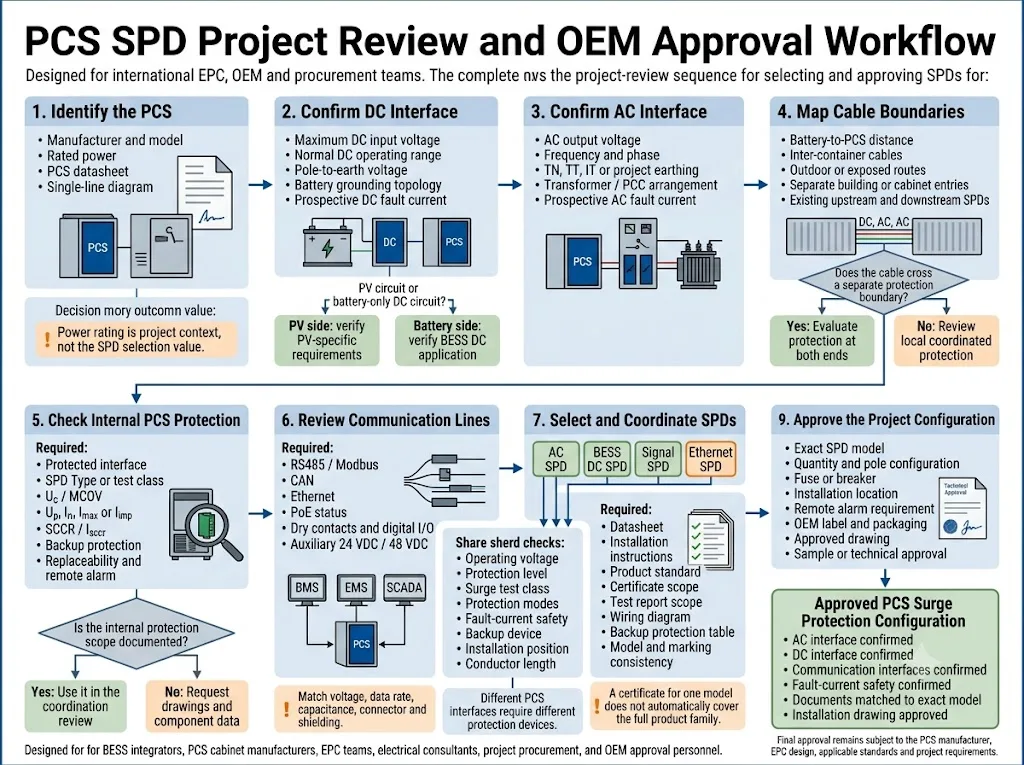
Ein praktischer Auswahlprozess für PCS SPD
Erfassen Sie jede leitfähige Schnittstelle.
Listen Sie den DC-Haupteingang, den AC-Anschluss, die Hilfsstromversorgungen, RS485, CAN, Ethernet, potenzialfreie Kontakte, Sensoren und Notstromkreise auf. Identifizieren Sie, welche Kabel das geerdete Gehäuse verlassen.
Dokumentieren Sie die tatsächlichen Betriebsgrenzen.
Ermitteln Sie die maximale DC-Spannung, AC-Spannung, Spannung gegen Erde, Hilfsspannung, Signalspannung sowie Informationen zur Stoßspannungsfestigkeit der Geräte.
Bestätigen Sie die Erdung und den Potenzialausgleich.
Identifizieren Sie das AC-Erdungssystem, die DC-Erdungstopologie, die Isolationsüberwachung, die Kabelschirmungsmethode und die Struktur des Potenzialausgleichs.
Identifizieren Sie die Überspannungsbelastung und die Schutzbereiche.
Überprüfen Sie das externe Blitzschutzsystem (LPS), die Außenleitungswege, die Containertrennung, die Kabellänge sowie vorhandene vorgeschaltete oder nachgeschaltete Überspannungsschutzgeräte (SPDs).
Überprüfen Sie die Überspannungs- und Fehlerkoordination.
Verifizieren Sie Uc oder MCOV, Up, die Stoßstromprüfklasse, die Schutzmodi, den prospektiven Fehlerstrom, die Absicherung sowie die Koordination mit anderen SPDs.
Schließen Sie die technische Freigabe ab.
Vergleichen Sie die vorgeschlagenen Modelle und die Verkabelung vor der Bestellung mit dem PCS-Handbuch, dem einpoligen Schaltplan des EPC, den geltenden Normen und den Projektspezifikationen.
Wie sich die Schutzlogik durch das BESS-Layout ändert
Batterie und PCS in einem Container
Interne Stromleitungswege können kurz sein und innerhalb eines geerdeten Gehäuses verbleiben. Überprüfen Sie den bereits installierten Schutz an jedem externen Zugang, bevor Sie zusätzliche Geräte hinzufügen.
Getrennte Batterie- und PCS-Container
Externe DC- und Kommunikationskabel bilden separate Schutzbereiche. Überprüfen Sie beide Kabelenden, die Leitungsführung, die Erdung und die Koordination zwischen den lokalen SPDs.
PCS im Versorgungsmaßstab mit Transformator
Überprüfen Sie den AC-Niederspannungsanschluss des PCS, die Transformatoranordnung, die Hauptschaltanlage, den verfügbaren Fehlerstrom, den vorgeschalteten Schutz und das Blitzschutzdesign.
Hybrides PV- und BESS-Projekt
Halten Sie PV-Strings, Batterie-Gleichstromkreise und Wechselrichterschnittstellen strikt getrennt. Betrachten Sie nicht jeden 1.500-V-Gleichstromkreis als dieselbe SPD-Anwendung.
IEC 62933-5-1:2024 enthält allgemeine Sicherheitsüberlegungen für netzgekoppelte elektrische Energiespeichersysteme. IEC 62933-5-2:2025 ergänzt Sicherheitsanforderungen für elektrochemische Energiespeichersysteme über deren gesamten Lebenszyklus.[11][12]
Diese Normen bilden den übergeordneten Sicherheitsrahmen für BESS. Die spezifische SPD muss dennoch anhand der relevanten Produktnorm für Wechselstrom, Gleichstrom oder Signale sowie des genehmigten Projektdesigns ausgewählt werden.
Häufige Fehler beim Überspannungsschutz von PCS
| Fehler | Warum es Risiken schafft | Bewährte Projektpraxis |
|---|---|---|
| Auswahl ausschließlich basierend auf der PCS-Leistung | MW oder kW definieren weder Spannung, Fehlerstrom, Erdung noch Exposition | Schnittstellenspezifische elektrische Daten erfassen |
| Verwendung einer einheitlichen SPD-Kategorie für alle Bereiche | Wechselstrom-, Batterie-Gleichstrom- und Kommunikationskreise weisen unterschiedliche Bedingungen auf | Jede Schnittstelle separat auswählen |
| Batterie-Gleichstrom automatisch wie PV-Gleichstrom behandeln | Anwendungsbereich, Quellenverhalten und Fehlerbedingungen können variieren | Die deklarierte BESS-Gleichstromanwendung verifizieren |
| Annahme, dass die interne SPD alle Bereiche abdeckt | Das interne Gerät schützt möglicherweise nur einen einzelnen Stromkreis oder Anschluss | Schaltplan und Komponentendaten anfordern |
| Ausschließlich Stromleitungen schützen | Ein Kommunikations- oder Hilfsspannungs-Transientenimpuls kann die Steuerung deaktivieren | Jeden extern geführten Leiter überprüfen |
| Voraussichtlichen Fehlerstrom ignorieren | Das SPD oder die Schutzeinrichtung löst einen Fehler möglicherweise nicht sicher aus | SCCR oder Isccr sowie den Backup-Schutz verifizieren |
| Lange SPD-Verbindungen verwenden | Verbindungsinduktivität erhöht die am PCS anliegende Spannung | Kurze, direkte Verbindungen und ordnungsgemäße Erdung verwenden |
Erforderliche Informationen vor einer PCS SPD-Bestellung
Eine nützliche Empfehlung erfordert mehr als nur „BESS PCS“ oder „1.500-V-Wechselrichter“. Stellen Sie die folgenden Daten zusammen, bevor Sie ein Angebot, ein Muster oder eine OEM-Konfiguration anfordern.
Vor der Modellfreigabe zu überprüfende Dokumente
- PCS-Datenblatt und Schnittstellenplan;
- AC- und DC-Einpolige Schaltpläne;
- Details zu internen SPD- oder Überspannungsschutzkomponenten;
- Berechnungen der voraussichtlichen AC- und DC-Fehlerströme;
- Datenblatt und Installationsanleitung für den Überspannungsschutz (SPD);
- Modellspezifisches Zertifikat oder Prüfberichtsumfang;
- Koordinierungstabelle für Vorsicherungen oder Schutzschalter;
- Genehmigter Schaltschrankaufbau und Verdrahtungsplan.
Ein Zertifikat für ein Modell deckt nicht automatisch jede Spannung, Polanordnung oder jedes Modul innerhalb derselben Produktfamilie ab. Stimmen Sie die Modellkennzeichnung, den Prüfberichtsumfang und die Projektkonfiguration aufeinander ab.
Übermitteln Sie diese Parameter an den SPD-Lieferanten
LEEYEE kann diese Details nutzen, um eine Vorauswahl an Modellen zu erstellen und Bedingungen zu identifizieren, die noch durch den PCS-Hersteller, Systemintegrator oder EPC bestätigt werden müssen.
CNSPD ist die auf Überspannungsschutz spezialisierte Plattform von LEEYEE für globale technische Einkäufer. Die endgültige Projektfreigabe unterliegt der PCS-Dokumentation, den geltenden Normen sowie der Prüfung durch die zuständigen Ingenieure.
Teilen Sie Ihre PCS-Schnittstellenanforderungen mit
Bitte senden Sie das PCS-Datenblatt, den DC-Spannungsbereich, das AC-Einliniendiagramm, die Kabelführungen, die Kommunikationsschnittstellen, die voraussichtlichen Fehlerströme sowie die erforderlichen Projektstandards.
LEEYEE kann die Anforderungen an AC, Batterie-DC, Signale, Ethernet, Backup-Schutz und Fernalarm prüfen, bevor ein OEM-Modell oder ein Projektmuster bestätigt wird.
Häufig gestellte Fragen
Benötigt jedes BESS-PCS einen SPD sowohl auf der AC- als auch auf der DC-Seite?
Beide Schnittstellen sollten bewertet werden, jedoch hängen die endgültige Anzahl und Position der SPDs vom internen PCS-Schutz, der Kabelführung, dem vorgeschalteten Schutz, der Blitzgefährdung, der Erdung, dem Potenzialausgleich und der Projektspezifikation ab.
Kann ein PV-DC-SPD am Batterieeingang eines PCS verwendet werden?
Gehen Sie nicht allein aufgrund der Spannungsfestigkeit von einer Eignung aus. Stellen Sie sicher, dass das spezifische Produkt für die Batterie-DC-Anwendung, die Topologie, den Fehlerstrom und die erforderliche Trennmethode zugelassen ist.
Reicht ein Typ-2-SPD für die AC-Seite des PCS aus?
Dies kann an bestimmten lokalen Geräten oder Verteilungspunkten angemessen sein, ist jedoch keine allgemeingültige Lösung. Der erforderliche SPD-Typ hängt von der Installationsgrenze, dem Blitzschutzsystem (LPS), dem vorgeschalteten Schutz und den geltenden Projektvorschriften ab.
Sollte ein SPD sowohl am Batterieschrank als auch am PCS installiert werden?
Bewerten Sie beide Enden, wenn die Geräte durch externe oder freiliegende Kabel getrennt sind oder wenn die Enden unterschiedliche Schutzzonen bilden. Ein kompaktes System innerhalb eines gemeinsamen Gehäuses erfordert möglicherweise eine andere koordinierte Anordnung.
Bestimmt die PCS-Leistung die Stoßstrombelastbarkeit des SPD?
Nein. Die PCS-Leistung und die Stoßstromkapazität des SPD beschreiben unterschiedliche Bedingungen. Die Auswahl des SPD hängt von der Überspannungsbelastung, der Einbauposition, der Prüfklasse, der Koordination und dem Projektrisiko ab.
Kann der interne SPD des PCS alle externen SPDs ersetzen?
Dies lässt sich ohne Dokumentation nicht beurteilen. Bestätigen Sie, welche Schnittstelle das interne Gerät schützt, sowie dessen Nennwerte, Anschlussart, Koordinationsgrenzen und ob entfernte Geräte außerhalb seines Schutzbereichs verbleiben.
Benötigt eine Glasfaser-Kommunikationsverbindung einen Signal-SPD?
Die Glasfaser selbst leitet keine Überspannung. Die zugehörige Stromversorgung, der Medienkonverter, die metallische Armierung, das Ethernet-Patchkabel und andere leitfähige Verbindungen müssen dennoch überprüft werden.
Welche Informationen sind für ein Angebot zu PCS-DC-SPDs am wichtigsten?
Geben Sie die maximale DC-Spannung, den Betriebsbereich, die Erdungskonfiguration, die Spannung zwischen Pol und Erde, den prospektiven Fehlerstrom, die Kabelführung, den Installationsort und den vorhandenen Schutz an.
Sollte ein Signal-SPD nur anhand des Protokollnamens ausgewählt werden?
Nein. Der Protokollname allein reicht nicht aus. Bestätigen Sie die Betriebsspannung, die Gleichtaktspannung, die Datenrate, die Kapazität, den Steckertyp, die Schirmung und die Erdungskonfiguration.
Referenzen
- Internationale elektrotechnische Kommission, IEC 62909-1:2025, Bidirektionale netzgekoppelte Stromrichter – Teil 1: Allgemeine Anforderungen und Sicherheitsanforderungen. Offizielle IEC-Veröffentlichungsseite.
- Internationale elektrotechnische Kommission, IEC 62477-1:2022, Sicherheitsanforderungen an leistungselektronische Stromversorgungssysteme und -geräte – Teil 1: Allgemeines. Offizielle IEC-Veröffentlichungsseite.
- Internationale elektrotechnische Kommission, IEC 61643-01:2024, Überspannungsschutzgeräte für Niederspannung – Teil 01: Allgemeine Anforderungen. Offizielle IEC-Veröffentlichungsseite.
- Internationale elektrotechnische Kommission, IEC 61643-11:2025, Überspannungsschutzgeräte für Niederspannung — Teil 11: Überspannungsschutzgeräte, die an AC-Niederspannungssysteme angeschlossen sind — Anforderungen und Prüfverfahren. Offizielle IEC-Veröffentlichungsseite.
- Internationale elektrotechnische Kommission, IEC 61643-12:2020, Überspannungsschutzgeräte für Niederspannung — Teil 12: Überspannungsschutzgeräte, die an Niederspannungssysteme angeschlossen sind — Auswahl- und Anwendungsgrundsätze. Offizielle IEC-Veröffentlichungsseite.
- Internationale elektrotechnische Kommission, IEC 61643-41:2025, Überspannungsschutzgeräte für Niederspannung – Teil 41: Überspannungsschutzgeräte für den Einsatz in Gleichstrom-Niederspannungsnetzen – Anforderungen und Prüfungen. Offizielle IEC-Veröffentlichungsseite.
- Internationale elektrotechnische Kommission, IEC 61643-31:2018, Überspannungsschutzgeräte für Niederspannung – Teil 31: Anforderungen und Prüfungen für Überspannungsschutzgeräte für Photovoltaik-Anwendungen. Offizielle IEC-Veröffentlichungsseite.
- Internationale elektrotechnische Kommission, IEC 61643-21:2025, Überspannungsschutzgeräte für Niederspannung – Teil 21: Überspannungsschutzgeräte für den Einsatz in Telekommunikations- und signalverarbeitenden Netzwerken – Anforderungen und Prüfungen. Offizielle IEC-Veröffentlichungsseite.
- Internationale elektrotechnische Kommission, IEC 61643-22:2015, Überspannungsschutzgeräte für Niederspannung – Teil 22: Überspannungsschutzgeräte für den Einsatz in Telekommunikations- und signalverarbeitenden Netzwerken – Auswahl- und Anwendungsprinzipien. Offizielle IEC-Veröffentlichungsseite.
- Internationale elektrotechnische Kommission, IEC 62305-4:2024, Blitzschutz – Teil 4: Elektrische und elektronische Systeme in baulichen Anlagen. Offizielle IEC-Veröffentlichungsseite.
- Internationale elektrotechnische Kommission, IEC 62933-5-1:2024, Elektrische Energiespeichersysteme – Teil 5-1: Sicherheitsanforderungen für netzgekoppelte EES-Systeme – Allgemeine Spezifikationen. Offizielle IEC-Veröffentlichungsseite.
- Internationale elektrotechnische Kommission, IEC 62933-5-2:2025, Elektrische Energiespeichersysteme – Teil 5-2: Sicherheitsanforderungen für netzgekoppelte EES-Systeme – Elektrochemische Systeme. Offizielle IEC-Veröffentlichungsseite.
- ABB, Schaltung & Schutz des 1500-V-Gleichstrombus in Energieumwandlungssystemen, Anwendungshinweis für PCS in PV-, BESS- und Wasserstoffanwendungen. Offizieller ABB-Anwendungshinweis.
