
Sistem konversi daya BESS menghubungkan sirkuit DC sisi baterai ke papan saklar AC, transformer, jaringan, atau beban lokal. PCS yang sama mungkin juga terhubung ke BMS, EMS, platform SCADA, pasokan tambahan, dan beberapa jaringan komunikasi.
Setiap antarmuka konduktif dapat menjadi jalur masuk lonjakan. Oleh karena itu, perlindungan lonjakan inverter PCS harus ditinjau sebagai masalah koordinasi antarmuka—bukan sebagai permintaan untuk satu SPD generik yang dipilih hanya dari daya PCS atau tegangan nominal.
Daftar Isi
Apakah Inverter PCS dalam BESS Membutuhkan Perlindungan Lonjakan?
Antarmuka AC, DC baterai, komunikasi, dan antarmuka tambahan dari PCS BESS harus dievaluasi untuk perlindungan lonjakan yang terkoordinasi.
Pengaturan akhir tergantung pada manual PCS, tegangan operasi maksimum, pengaturan penanaman tanah dan peng grounding-an, arus kesalahan potensial, penataan kabel, paparan petir, perlindungan internal PCS, dan spesifikasi proyek.[1][2]
| Antarmuka PCS | Arah Perlindungan | Konfirmasi utama |
|---|---|---|
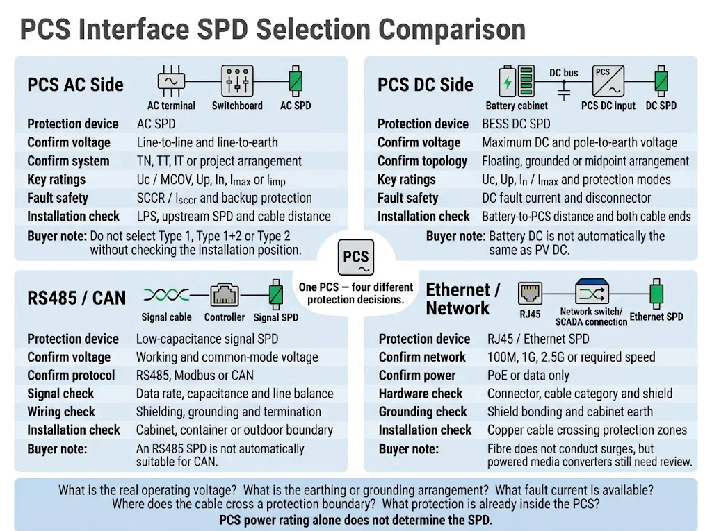
| Input DC | BESS DC SPD dipilih untuk sirkuit sisi baterai yang sebenarnya | Tegangan DC maksimum, tegangan tiang ke tanah, topologi pembumian, dan arus gangguan |
| Koneksi AC | SPD AC terkoordinasi di batas PCS atau panel saklar yang relevan | Tegangan AC, sistem pembumian, LPS, SPD hulu, dan posisi instalasi |
| RS485 / CAN | Signal SPD yang sesuai dengan sirkuit | Tegangan kerja, laju data, kapasitansi, pelindung, dan pembumian |
| Ethernet | Network SPD dimana kabel tembaga melintasi batas perlindungan | Kecepatan jaringan, status PoE, konektor, kategori kabel, dan pengikatan pelindung |
| Suplai tambahan | SPD AC atau DC sesuai dengan sirkuit tambahan yang sebenarnya | Tegangan suplai, sumber, paparan kabel, dan level ketahanan peralatan |
Makna pembeli: “1 MW PCS” atau “1.500 V PCS” tidak cukup informasi untuk pemilihan SPD. Pemasok memerlukan data listrik dan instalasi yang spesifik untuk antarmuka.
Ruang lingkup: Panduan ini berfokus pada SPD eksternal dan tingkat kabinet untuk antarmuka daya PCS, komunikasi, dan tambahan. Ini tidak mencakup desain sirkuit lonjakan TVS, MOV, GDT, atau PCB pada tingkat komponen di dalam konverter.
Di Halaman Ini
- Tentukan batas perlindungan PCS
- Perlindungan lonjakan sisi AC PCS
- Perlindungan input DC PCS
- Apakah SPD internal PCS sudah cukup?
- Antarmuka komunikasi dan bantuan
- Pemosisian grounding dan instalasi
- Proses pemilihan proyek
- Tata letak BESS umum
- Kesalahan umum
- Daftar periksa OEM dan proyek
- Pertanyaan yang Sering Diajukan
Tentukan Batas Perlindungan di Sekitar PCS
PCS adalah konverter daya dua arah antara sumber penyimpanan energi DC dan sistem listrik AC. IEC 62909-1:2025 mencakup aspek umum dan keselamatan dari konverter daya yang terhubung ke jaringan dua arah yang relevan dengan tegangan sistem tidak melebihi 1.000 V AC atau 1.500 V DC.[1]
IEC 62477-1:2022 memberikan kerangka kerja keselamatan yang lebih luas untuk sistem konverter elektronika daya dan fungsi kendali, proteksi, pemantauan, serta pengukurannya yang terkait.[2]
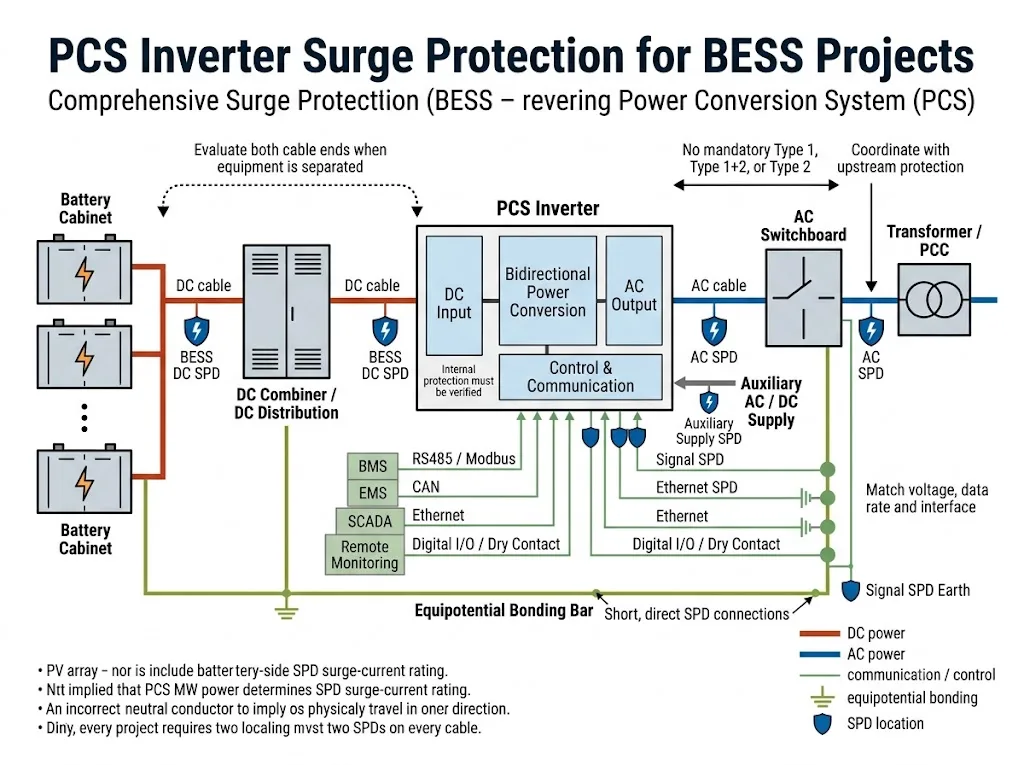
Untuk proteksi lonjakan, PCS tidak boleh diperlakukan sebagai satu kotak tertutup. Tim proyek harus mengidentifikasi setiap jalur konduktif yang masuk ke atau keluar dari selungkupnya.
Berikan perhatian khusus pada kabel yang meninggalkan satu kabinet, kontainer, bangunan, atau zona terikat dan memasuki yang lain. Jalur-jalur ini dapat mengekspos PCS terhadap transien terkonduksi atau terinduksi meskipun selungkup utama sudah memiliki proteksi internal.[10]
Pertanyaan praktisnya bukan hanya “Apakah PCS memiliki SPD?” Proyek harus menanyakan:
Antarmuka mana yang melintasi batas proteksi eksternal atau internal, proteksi apa yang sudah ada, dan tegangan apa yang dapat ditahan dengan aman oleh terminal PCS?
Bagaimana Seharusnya Sisi AC PCS Dilindungi?
Antarmuka AC PCS dapat terhubung ke switchboard tegangan rendah, transformator, titik kopling bersama, atau mikrogrid lokal. Posisi SPD yang tepat bergantung pada tempat lonjakan dapat masuk dan lokasi terminal PCS yang dilindungi.
IEC 61643-11:2025 berlaku untuk SPD yang terhubung ke sistem daya AC tegangan rendah. IEC 61643-12:2020 memberikan prinsip pemilihan, penempatan, pengoperasian, dan koordinasi untuk SPD daya AC.[4][5]
Titik evaluasi umum pada sisi AC
| Posisi | Tujuan proteksi | Apa yang harus dikonfirmasi |
|---|---|---|
| Papan utama LV atau batas layanan AC | Membatasi lonjakan yang masuk dari suplai, transformator, atau jalur AC eksternal | Risiko petir, LPS, konfigurasi suplai, arus gangguan, dan aturan proyek |
| Terminal AC PCS atau panel PCS lokal | Membatasi tegangan sisa atau tegangan terinduksi lokal di dekat antarmuka PCS | Jarak dari SPD hulu, rute kabel, koordinasi, dan manual PCS |
| Distribusi AC bantu | Melindungi pengendali, kipas, HVAC, pemanas, UPS, dan suplai pemantauan | Sumber terpisah, tegangan, pembumian, dan paparan kabel |
Ini adalah posisi evaluasi. Hal ini tidak berarti bahwa setiap BESS memerlukan SPD di ketiga titik tersebut.
Konfirmasikan tegangan pada setiap mode proteksi
Jangan memilih SPD AC hanya dari tegangan antar-fasa. Pemasok perlu mengetahui tegangan pada setiap mode proteksi yang dimaksud, termasuk fasa-ke-netral atau fasa-ke-bumi jika berlaku.
Pengaturan pembumian juga harus diidentifikasi. Sistem TN-S, TN-C-S, TT, dan IT dapat memerlukan konfigurasi sambungan yang berbeda serta perlakuan yang berbeda terhadap jalur netral-ke-bumi.
Jangan menyatakan bahwa setiap sambungan AC PCS memerlukan proteksi Tipe 1, Tipe 1+2, atau Tipe 2. Jenis SPD yang diperlukan bergantung pada batas instalasi, jalur arus petir, LPS eksternal, proteksi hulu, dan aturan proyek yang berlaku.[5][10]
Periksa keselamatan hubung singkat secara terpisah dari peringkat lonjakan
In, Imax, dan Iimp menggambarkan kinerja uji lonjakan. Ketiganya tidak menjelaskan apakah SPD tetap aman selama gangguan pada frekuensi daya.
Konfirmasikan arus hubung singkat prospektif, sekering atau pemutus hulu, serta ketentuan proteksi cadangan dari produsen SPD. Pedoman terkait SPD SCCR dan panduan Isccr menjelaskan pemeriksaan proyek ini secara lebih rinci.
Bagaimana Seharusnya Input DC PCS Dilindungi?
Input DC PCS dapat dihubungkan langsung ke rak baterai, kabinet baterai, DC combiner, atau kabinet distribusi DC terpisah. Halaman ini berfokus pada batas proteksi pada input PCS dan koordinasinya dengan peralatan di sisi baterai.
IEC 61643-41:2025 berlaku untuk SPD pada rangkaian daya DC dan peralatan dengan rating hingga 1.500 V DC. IEC 61643-01:2024 memuat persyaratan umum SPD yang digunakan bersama dengan bagian-bagian khusus rangkaian yang relevan dari seri IEC 61643.[3][6]
Perangkat dengan penandaan “1.500 VDC” tidak otomatis cocok untuk input baterai PCS. Aplikasi yang dinyatakan, tegangan operasi kontinu, topologi DC, mode proteksi, kemampuan arus gangguan, dan metode pemutusan harus diverifikasi.
DC baterai tidak otomatis sama dengan DC PV
IEC 61643-31:2018 berlaku untuk SPD yang dihubungkan ke sisi DC instalasi fotovoltaik. IEC 61643-41:2025 membahas SPD untuk sistem daya DC tegangan rendah non-PV.[6][7]
SPD PV tidak boleh disetujui untuk antarmuka PCS di sisi baterai hanya karena nilai tegangan yang tertera tampak sesuai. Produsen harus menyatakan produk yang tepat yang cocok untuk rangkaian DC baterai dan susunan koneksi yang dimaksud.
Data input DC PCS untuk dikonfirmasi
- tegangan input DC maksimum, termasuk tegangan pengisian maksimum;
- rentang operasi normal PCS;
- tegangan dari tiap kutub ke bumi;
- pengaturan mengambang, terhubung ke ground, bipolar, atau titik tengah;
- arus hubung singkat prospektif pada terminal PCS;
- perlindungan yang ada di dalam kabinet baterai dan PCS;
- sekering cadangan, pemutus arus, atau pemutus daya terkoordinasi yang diperlukan.
Uc harus tetap sesuai selama pengoperasian normal dan kondisi sistem yang ditentukan. Uc yang terlalu rendah dapat meningkatkan tekanan dan penuaan dini. Uc yang terlalu tinggi secara tidak perlu dapat meningkatkan tingkat perlindungan voltase yang mencapai PCS.
Perlindungan kabinet baterai dan perlindungan input PCS adalah batas yang berbeda
| Titik perlindungan | Area utama yang dilindungi | Keputusan proyek |
|---|---|---|
| Output kabinet baterai | Terminal baterai, sirkuit BMS terdekat, dan kabel keluar | Periksa apakah proteksi lokal sudah disertakan dan didokumentasikan |
| Combiner DC atau kabinet distribusi | Bus pengumpul, cabang, dan jalur kabel yang terhubung | Tinjau perubahan kondisi arus gangguan dan pengikatan (bonding) |
| Masukan DC PCS | Terminal input PCS dan elektronika daya di sekitarnya | Periksa tegangan sisa, induksi lokal, dan koordinasi dengan SPD jarak jauh |
Jika baterai dan PCS menggunakan satu selungkup (enclosure) ringkas yang terikat (bonded), satu pengaturan terkoordinasi mungkin sudah cukup. Jika keduanya dipisahkan oleh kabel eksternal, kontainer yang berbeda, atau jalur yang terbuka, kedua ujung harus dievaluasi.
Tidak ada ambang batas jarak kabel universal untuk setiap arsitektur BESS. Keputusan harus mengikuti zona proteksi aktual, rute kabel, risiko tegangan induksi, tingkat ketahanan peralatan, dan studi koordinasi proyek.[10]
Jangan memasang SPD khusus AC pada bus DC baterai kecuali produk dan mode koneksinya secara eksplisit diberi nilai (rated) untuk aplikasi DC tersebut. Kondisi interupsi gangguan DC dan pemutusan harus ditangani oleh desain produk yang dinyatakan.
Untuk pemilihan mendetail di seluruh sistem sisi baterai, gunakan panduan SPD DC BESS yang terpisah. Halaman ini tetap berfokus pada antarmuka input PCS.
Apakah SPD Di Dalam PCS Cukup?
Beberapa produk PCS mengandung SPD AC internal, SPD DC, supresor tingkat PCB, atau komponen pembatas tegangan lainnya. Ini dapat melindungi sirkuit internal yang ditentukan, tetapi tidak secara otomatis membuktikan bahwa setiap kabel eksternal dan kabinet jarak jauh terlindungi.
Proteksi internal mungkin tidak mencakup:
- kabinet baterai jarak jauh;
- kabel DC antar-kontainer yang panjang;
- layanan AC utama atau switchboard hulu;
- sirkuit bantu yang disuplai secara terpisah;
- jalur komunikasi yang masuk dari kabinet atau bangunan lain;
- lonjakan tegangan yang diinduksi di luar batas koordinasi perangkat internal.
Konfirmasi Item-Item Ini Sebelum Menghapus Perlindungan Eksternal
Pernyataan brosur seperti "proteksi lonjakan disertakan" tidak cukup untuk persetujuan proyek. Mintalah diagram sirkuit PCS, jadwal komponen, lembar data SPD, atau manual teknis.
Penghapusan SPD eksternal harus didukung oleh koordinasi yang didokumentasikan. Hal ini tidak boleh didasarkan hanya pada ikon fitur produk atau asumsi bahwa proteksi internal mencakup BESS secara keseluruhan.
Lindungi Komunikasi dan Antarmuka Tambahan
PCS dapat tetap tidak rusak pada tahap daya utamanya namun tetap menjadi tidak tersedia karena port komunikasi, input kontroler, atau catu daya bantu mengalami kegagalan.
IEC 61643-21:2025 berlaku untuk SPD yang terhubung ke jaringan telekomunikasi dan persinyalan. Standar ini juga mencakup jaringan yang menyediakan daya dan data pada konduktor yang sama, termasuk aplikasi PoE. IEC 61643-22:2015 menyediakan prinsip pemilihan dan aplikasi untuk jaringan ini.[8][9]
| Antarmuka PCS | Pemeriksaan pemilihan | Batas tipikal untuk ditinjau |
|---|---|---|
| RS485 \/ Modbus | Tegangan kerja, tegangan mode umum, kecepatan data, kapasitansi, dan pelindung (shielding) | Kabel yang keluar dari kabinet, kontainer, atau bangunan |
| Bus CAN | Tegangan CAN, kecepatan transmisi, topologi, dan keseimbangan jalur | Koneksi antara PCS dan pengontrol baterai jarak jauh |
| Ethernet \/ PoE | Kecepatan jaringan, standar PoE, kategori kabel, konektor, dan pelindung (shield) | Tautan tembaga antar kabinet, kontainer, atau bangunan |
| I/O digital dan kontak kering (dry contacts) | Tegangan sirkuit, arus, perilaku sinyal, dan ketahanan kontroler | Alarm eksternal, sirkuit darurat, dan kontak jarak jauh |
| Daya bantu 24 VDC / 48 VDC | Tegangan suplai maksimum, sumber, ketahanan beban, dan pembumian | Suplai PLC, HMI, gateway, atau sensor eksternal |
SPD RS485 tidak secara otomatis cocok untuk CAN. SPD bus baterai tidak cocok untuk kontroler 24 V hanya karena kedua sirkuit tersebut adalah DC. Setiap antarmuka memerlukan tinjauan tegangan dan sinyalnya sendiri.
Gunakan panduan proteksi lonjakan Modbus dan panduan pemilihan pelindung lonjakan RJ45 ketika pemilihan model di tingkat protokol diperlukan.
Serat optik tidak menghantarkan lonjakan arus melalui serat itu sendiri. Namun, media converter, catu daya, pelindung logam, dan koneksi tembaga di sekitarnya mungkin tetap memerlukan perlindungan.
Pemasangan Penanaman Tanah, Penyambungan, dan Posisi Instalasi
SPD membatasi tegangan melalui seluruh jalur koneksinya. Konduktor yang panjang atau melingkar menambah tegangan induktif selama transien cepat dan dapat mengurangi perlindungan efektif pada terminal PCS.
IEC 62305-4:2024 memberikan persyaratan untuk desain, pemasangan, inspeksi, pemeliharaan, dan pengujian langkah-langkah perlindungan lonjakan arus untuk sistem kelistrikan dan elektronik di dalam struktur.[10]
Pasang di dekat batas yang ditentukan
Tempatkan SPD di dekat pintu masuk kabel, sambungan bus, atau terminal peralatan yang menentukan batas perlindungan yang dimaksud. Ikuti petunjuk produsen PCS dan SPD untuk posisi pemasangan yang tepat.
Jaga koneksi tetap pendek dan langsung
Hindari putaran dan jalur memutar yang tidak perlu. Arahkan koneksi SPD ke konduktor yang dilindungi dan titik ikatan (bonding point) selangsung mungkin.
Integrasikan semua kabinet ke dalam desain bonding
Kabinet baterai, enklosur PCS, switchboard AC, kabinet komunikasi, layar kabel, dan kontainer logam harus dimasukkan ke dalam desain equipotential-bonding proyek.
SPD tidak dapat mengompensasi sistem arde pelindung dan bonding yang hilang atau dirancang dengan buruk.
Tinjau entri daya dan sinyal secara bersamaan
Kabel AC, DC, dan komunikasi sering kali mengikuti rute yang berbeda. Melindungi entri daya sambil membiarkan kabel RS485 atau Ethernet yang dirutekan secara eksternal tidak ditinjau dapat menyisakan jalur lonjakan arus lain ke pengontrol PCS.
Panjang konduktor, penampang, pemisahan, perlindungan cadangan, dan metode koneksi yang tepat harus mengikuti aturan pemasangan yang berlaku, manual PCS, instruksi SPD, dan gambar proyek yang disetujui.
Proses Pemilihan SPD PCS yang Praktis
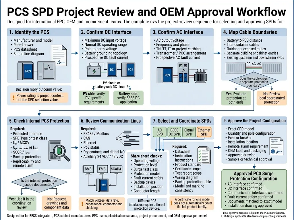
Petakan setiap antarmuka konduktif
Daftar input DC utama, koneksi AC, suplai tambahan, RS485, CAN, Ethernet, kontak kering, sensor, dan sirkuit darurat. Identifikasi kabel mana yang keluar dari enklosur yang di-bonding.
Catat batas operasional sebenarnya
Dapatkan informasi tegangan DC maksimum, tegangan AC, tegangan kutub-ke-bumi, tegangan tambahan, tegangan sinyal, dan ketahanan impuls peralatan.
Konfirmasi pentanahan (earthing) dan pengardean (grounding)
Identifikasi sistem pentanahan AC, topologi pengardean DC, pengaturan pemantauan isolasi, metode pelindung kabel, dan struktur equipotential-bonding.
Identifikasi paparan lonjakan arus dan batasannya
Tinjau LPS eksternal, rute luar ruangan, pemisahan kontainer, panjang kabel, dan SPD hulu atau hilir yang ada.
Periksa koordinasi lonjakan arus dan gangguan
Verifikasi Uc atau MCOV, Up, kelas uji lonjakan arus, mode perlindungan, arus gangguan prospektif, perangkat cadangan, dan koordinasi dengan SPD lain.
Selesaikan persetujuan teknis
Bandingkan model dan pengabelan yang diusulkan dengan manual PCS, diagram satu baris EPC, standar yang berlaku, dan spesifikasi proyek sebelum memesan.
Bagaimana Logika Perlindungan Berubah Berdasarkan Tata Letak BESS
Baterai dan PCS dalam Satu Kontainer
Rute daya internal mungkin pendek dan tetap berada dalam satu enklosur yang di-bonding. Verifikasi perlindungan yang sudah terpasang di setiap entri eksternal sebelum menambahkan perangkat duplikat.
Pisahkan Kontainer Baterai dan PCS
Kabel DC dan komunikasi eksternal menciptakan batas yang terpisah. Tinjau kedua ujung kabel, paparan rute, bonding, dan koordinasi antar SPD lokal.
PCS Skala Utilitas dengan Transformator
Tinjau terminal AC tegangan rendah PCS, pengaturan transformator, switchgear utama, arus gangguan yang tersedia, perlindungan hulu, dan desain risiko petir.
Proyek Hibrida PV dan BESS
Jaga agar string PV, sirkuit DC baterai, dan antarmuka konverter terpisah dengan jelas. Jangan memperlakukan setiap sirkuit 1.500 VDC sebagai aplikasi SPD yang sama.
IEC 62933-5-1:2024 menyediakan pertimbangan keselamatan umum untuk sistem penyimpanan energi listrik yang terintegrasi dengan jaringan. IEC 62933-5-2:2025 menambahkan persyaratan keselamatan untuk sistem penyimpanan energi elektrokimia di sepanjang siklus hidupnya.[11][12]
Standar-standar ini menetapkan konteks keselamatan BESS yang lebih luas. SPD yang tepat harus tetap dipilih menggunakan standar produk AC, DC, atau sinyal yang relevan serta desain proyek yang disetujui.
Kesalahan Umum dalam Perlindungan Lonjakan PCS
| Kesalahan | Mengapa hal ini menimbulkan risiko | Praktik proyek yang lebih baik |
|---|---|---|
| Memilih hanya dari daya PCS | MW atau kW tidak menentukan tegangan, arus gangguan, pentanahan, atau paparan | Kumpulkan data kelistrikan khusus antarmuka |
| Menggunakan satu kategori SPD di mana-mana | Sirkuit AC, DC baterai, dan komunikasi memiliki kondisi yang berbeda | Pilih setiap antarmuka secara terpisah |
| Memperlakukan DC baterai sebagai DC PV secara otomatis | Cakupan aplikasi, perilaku sumber, dan kondisi gangguan bisa berbeda | Verifikasi aplikasi DC BESS yang dinyatakan |
| Mengasumsikan SPD internal mencakup semuanya | Perangkat internal mungkin hanya melindungi satu sirkuit atau terminal | Minta diagram sirkuit dan data komponen |
| Hanya melindungi saluran listrik | Transien komunikasi atau transien tambahan dapat menonaktifkan pengontrol | Tinjau setiap konduktor yang dirutekan secara eksternal |
| Mengabaikan arus gangguan prospektif | SPD atau perangkat cadangan mungkin tidak dapat memutus gangguan dengan aman | Verifikasi SCCR atau Isccr dan perlindungan cadangan |
| Menggunakan sambungan SPD yang panjang | Induktansi sambungan meningkatkan tegangan yang mencapai PCS | Gunakan sambungan yang pendek dan langsung serta ikatan (bonding) yang tepat |
Informasi yang Diperlukan Sebelum Memesan SPD PCS
Rekomendasi yang berguna memerlukan lebih dari sekadar "BESS PCS" atau "inverter 1.500 V." Siapkan data berikut sebelum meminta penawaran, sampel, atau konfigurasi OEM.
Dokumen untuk Memverifikasi Sebelum Persetujuan Model
- Lembar data PCS dan jadwal antarmuka;
- Diagram garis tunggal AC dan DC;
- detail komponen SPD internal atau perlindungan lonjakan arus;
- perhitungan arus gangguan AC dan DC prospektif;
- lembar data SPD dan instruksi pemasangan;
- sertifikat spesifik model atau cakupan laporan pengujian;
- tabel koordinasi sekring cadangan atau pemutus arus;
- tata letak kabinet dan gambar pengkabelan yang disetujui.
Sertifikat untuk satu model tidak secara otomatis mencakup setiap tegangan, susunan kutub, atau modul dalam keluarga produk yang sama. Sesuaikan dengan penandaan model, cakupan laporan, dan konfigurasi proyek.
Kirim Parameter Ini ke Pemasok SPD
LEEYEE dapat menggunakan detail ini untuk menyiapkan daftar model singkat dan mengidentifikasi kondisi yang masih memerlukan konfirmasi oleh produsen PCS, integrator sistem, atau EPC.
CNSPD adalah platform LEEYEE yang berfokus pada perlindungan lonjakan arus untuk pembeli teknis global. Persetujuan proyek akhir tetap bergantung pada dokumentasi PCS, standar yang berlaku, dan tinjauan teknik yang bertanggung jawab.
Bagikan Persyaratan Antarmuka PCS Anda
Kirimkan lembar data PCS, rentang tegangan DC, diagram garis tunggal AC, rute kabel, antarmuka komunikasi, arus gangguan prospektif, dan standar proyek yang diperlukan.
LEEYEE dapat meninjau persyaratan AC, DC baterai, sinyal, Ethernet, perlindungan cadangan, dan alarm jarak jauh sebelum model OEM atau sampel proyek dikonfirmasi.
Pertanyaan yang Sering Diajukan
Apakah setiap BESS PCS memerlukan SPD pada sisi AC dan DC?
Kedua antarmuka harus dinilai, namun jumlah dan posisi akhir SPD bergantung pada perlindungan PCS internal, rute kabel, perlindungan hulu, paparan petir, pembumian, ikatan, dan spesifikasi proyek.
Bisakah SPD DC PV digunakan pada input baterai PCS?
Jangan berasumsi kesesuaian hanya dari nilai tegangannya saja. Pastikan bahwa produk tersebut memang dinyatakan untuk aplikasi DC baterai, topologi, arus gangguan, dan metode pemutusan yang diperlukan.
Apakah SPD Tipe 2 cukup untuk sisi AC PCS?
Ini mungkin sesuai di beberapa posisi peralatan lokal atau distribusi, tetapi ini bukan jawaban universal. Tipe SPD yang diperlukan bergantung pada batas instalasi, LPS, perlindungan hulu, dan aturan proyek yang berlaku.
Apakah SPD harus dipasang di kabinet baterai dan PCS?
Evaluasi kedua sisi ketika peralatan dipisahkan oleh kabel eksternal atau terbuka, atau ketika kedua sisi membentuk batas perlindungan yang berbeda. Sistem ringkas di dalam satu selungkup yang terikat (bonded enclosure) mungkin menggunakan pengaturan terkoordinasi yang berbeda.
Apakah daya PCS menentukan peringkat arus lonjakan SPD?
Tidak. Daya PCS dan kemampuan arus lonjakan SPD menjelaskan kondisi yang berbeda. Pemilihan SPD bergantung pada paparan lonjakan, posisi pemasangan, kelas uji, koordinasi, dan risiko proyek.
Bisakah SPD internal PCS menggantikan semua SPD eksternal?
Hal ini tidak dapat disimpulkan tanpa dokumentasi. Konfirmasikan antarmuka mana yang dilindungi oleh perangkat internal, peringkatnya, mode koneksi, batas koordinasi, dan apakah peralatan jarak jauh tetap berada di luar batas perlindungannya.
Apakah tautan komunikasi serat optik memerlukan SPD sinyal?
Serat optik itu sendiri tidak menghantarkan lonjakan. Catu daya yang terkait, konverter media, pelindung logam (metallic armour), kabel patch Ethernet, dan koneksi konduktif lainnya harus tetap ditinjau.
Informasi apa yang paling penting untuk penawaran SPD DC PCS?
Berikan tegangan DC maksimum, rentang operasi, pengaturan pentanahan, tegangan kutub ke bumi, arus gangguan prospektif, rute kabel, posisi pemasangan, dan perlindungan yang ada.
Haruskah SPD sinyal dipilih hanya berdasarkan nama protokol?
Tidak. Nama protokol saja tidak cukup. Konfirmasikan tegangan kerja, tegangan mode umum (common-mode voltage), kecepatan data, kapasitansi, konektor, pelindung, dan pengaturan pentanahan.
Referensi
- Komisi Elektroteknik Internasional, IEC 62909-1:2025, Konverter daya dua arah yang terhubung ke jaringan — Bagian 1: Persyaratan umum dan keselamatan. Halaman publikasi resmi IEC.
- Komisi Elektroteknik Internasional, IEC 62477-1:2022, Persyaratan keselamatan untuk sistem dan peralatan konverter daya elektronik — Bagian 1: Umum. Halaman publikasi resmi IEC.
- Komisi Elektroteknik Internasional, IEC 61643-01:2024, Perangkat pelindung lonjakan tegangan rendah — Bagian 01: Persyaratan umum. Halaman publikasi resmi IEC.
- Komisi Elektroteknik Internasional, IEC 61643-11:2025, Perangkat pelindung lonjakan arus tegangan rendah — Bagian 11: Perangkat pelindung lonjakan arus yang terhubung ke sistem daya tegangan rendah AC — Persyaratan dan metode pengujian. Halaman publikasi resmi IEC.
- Komisi Elektroteknik Internasional, IEC 61643-12:2020, Perangkat pelindung lonjakan arus tegangan rendah — Bagian 12: Perangkat pelindung lonjakan arus yang terhubung ke sistem daya tegangan rendah — Prinsip pemilihan dan penerapan. Halaman publikasi resmi IEC.
- Komisi Elektroteknik Internasional, IEC 61643-41:2025, Perangkat pelindung lonjakan tegangan rendah — Bagian 41: Perangkat pelindung lonjakan yang terhubung ke sistem daya tegangan rendah DC — Persyaratan dan metode uji. Halaman publikasi resmi IEC.
- Komisi Elektroteknik Internasional, IEC 61643-31:2018, Perangkat pelindung lonjakan tegangan rendah — Bagian 31: Persyaratan dan metode uji untuk SPD untuk instalasi fotovoltaik. Halaman publikasi resmi IEC.
- Komisi Elektroteknik Internasional, IEC 61643-21:2025, Perangkat pelindung lonjakan tegangan rendah — Bagian 21: Perangkat pelindung lonjakan yang terhubung ke jaringan telekomunikasi dan persinyalan — Persyaratan dan metode uji. Halaman publikasi resmi IEC.
- Komisi Elektroteknik Internasional, IEC 61643-22:2015, Perangkat pelindung lonjakan tegangan rendah — Bagian 22: Perangkat pelindung lonjakan yang terhubung ke jaringan telekomunikasi dan persinyalan — Prinsip pemilihan dan aplikasi. Halaman publikasi resmi IEC.
- Komisi Elektroteknik Internasional, IEC 62305-4:2024, Perlindungan terhadap petir — Bagian 4: Sistem listrik dan elektronik dalam bangunan. Halaman publikasi resmi IEC.
- Komisi Elektroteknik Internasional, IEC 62933-5-1:2024, Sistem penyimpanan energi listrik — Bagian 5-1: Pertimbangan keselamatan untuk sistem EES yang terintegrasi dengan jaringan — Spesifikasi umum. Halaman publikasi resmi IEC.
- Komisi Elektroteknik Internasional, IEC 62933-5-2:2025, Sistem penyimpanan energi listrik — Bagian 5-2: Persyaratan keselamatan untuk sistem EES yang terintegrasi dengan jaringan — Sistem berbasis elektrokimia. Halaman publikasi resmi IEC.
- ABB, Peralihan & Perlindungan Bus DC 1500 V dalam Sistem Konversi Daya, catatan aplikasi yang membahas PCS yang digunakan dalam aplikasi PV, BESS, dan hidrogen. Catatan aplikasi resmi ABB.
