
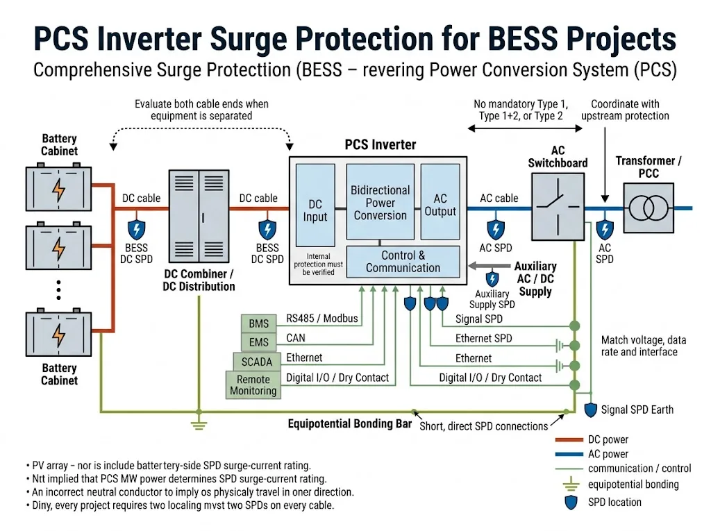
Un sistema di conversione di potenza BESS collega il circuito DC lato batteria a un quadro elettrico AC, trasformatore, rete o carico locale. Lo stesso PCS può anche collegarsi a un BMS, EMS, piattaforma SCADA, alimentazione ausiliaria e diverse reti di comunicazione.
Ogni interfaccia conduttiva può diventare un percorso di ingresso per le sovratensioni. La protezione dalle sovratensioni dell'inverter PCS dovrebbe quindi essere rivista come un problema di coordinazione delle interfacce, non come una richiesta per un SPD generico selezionato solo in base alla potenza del PCS o alla tensione nominale.
Indice dei contenuti
Un inverter PCS in un BESS ha bisogno di protezione contro le sovratensioni?
Le interfacce AC, DC della batteria, di comunicazione e ausiliarie di un BESS PCS dovrebbero essere valutate per una protezione coordinata contro le sovratensioni.
La disposizione finale dipende dal manuale del PCS, dalle massime tensioni operative, dagli allineamenti di messa a terra, dal potenziale di guasto corrente, dal percorso dei cavi, dall'esposizione ai fulmini, dalla protezione interna del PCS e dalla specifica del progetto.[1][2]
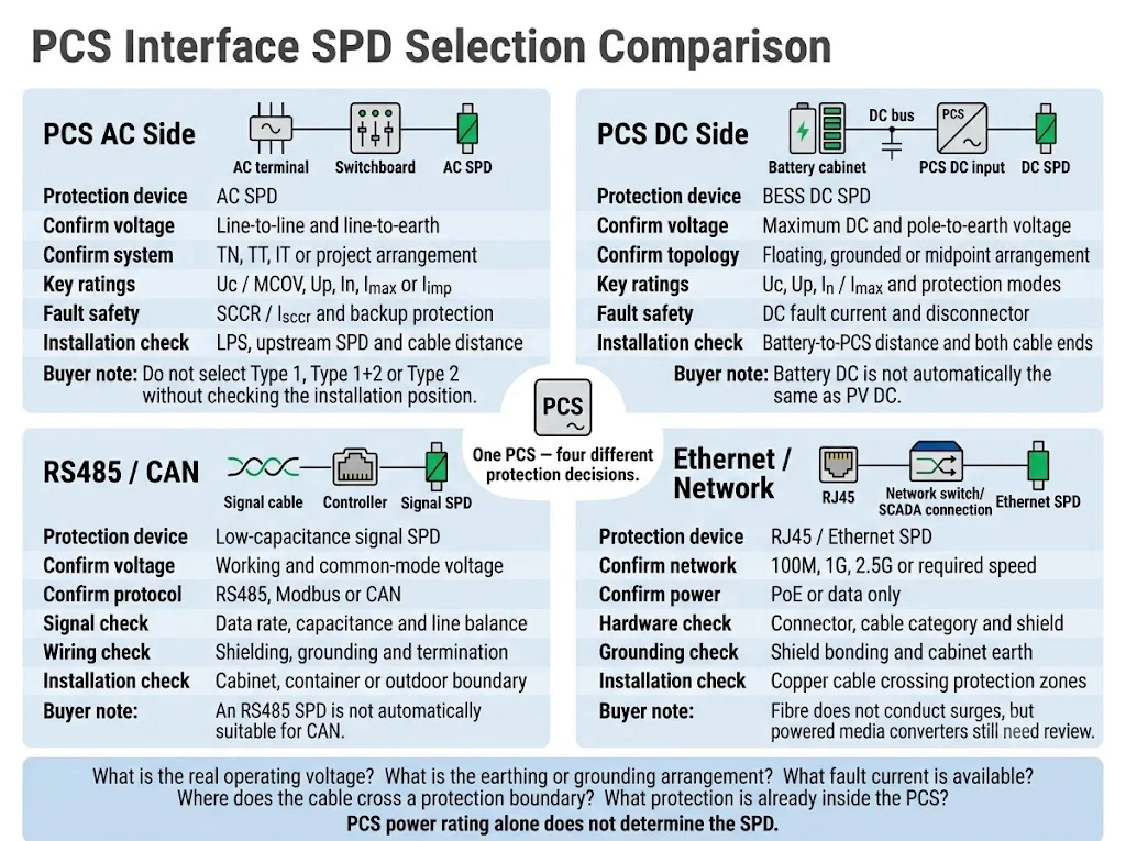
| Interfaccia PCS | Direzione di protezione | Conferma principale |
|---|---|---|
| Ingresso DC | SPD DC BESS selezionato per il circuito reale lato batteria | Massima tensione DC, tensione di terra, topologia di messa a terra e corrente di guasto |
| Collegamento AC | SPD AC coordinato al PCS pertinente o al confine del quadro elettrico | Tensione AC, sistema di messa a terra, LPS, SPD a monte e posizione di installazione |
| RS485 / CAN | SPD di segnale abbinata al circuito | Tensione di lavoro, velocità di trasmissione dati, capacità, schermatura e messa a terra |
| Ethernet | SPD di rete dove il cablaggio in rame attraversa un confine di protezione | Velocità di rete, stato PoE, connettore, categoria del cavo e legame della schermatura |
| Alimentazione ausiliaria | SPD AC o DC secondo il circuito ausiliario reale | Tensione di alimentazione, sorgente, esposizione del cavo e livello di resistenza delle attrezzature |
Significato dell'acquirente: “1 MW PCS” o “1.500 V PCS” non sono informazioni sufficienti per la selezione dello SPD. Il fornitore ha bisogno di dati elettrici e di installazione specifici per l'interfaccia.
Ambito: Questa guida si concentra sugli SPD esterni e a livello di armadio per potenza PCS, comunicazione e interfacce ausiliarie. Non tratta del design di circuiti di sovratensione a livello di componente come TVS, MOV, GDT o PCB all'interno del convertitore.
In questa pagina
- Definire il confine di protezione PCS
- Protezione da sovratensioni AC del PCS
- Protezione dell'ingresso DC del PCS
- La SPD interna del PCS è sufficiente?
- Interfacce di comunicazione e ausiliarie
- Messa a terra e posizione d'installazione
- Processo di selezione del progetto
- Layout comuni del BESS
- Errori comuni
- Checklist OEM e progetto
- Domande frequenti
Definire il confine di protezione attorno al PCS
Un PCS è un convertitore di potenza bidirezionale tra una sorgente di energia DC e un sistema elettrico AC. La IEC 62909-1:2025 tratta aspetti generali e di sicurezza dei convertitori di potenza bidirezionali collegati alla rete con tensioni di sistema non superiori a 1.000 V AC o 1.500 V DC.[1]
La IEC 62477-1:2022 fornisce un quadro di sicurezza più ampio per i sistemi di conversione di potenza elettronica e le loro funzioni associate di controllo, protezione, monitoraggio e misura.[2]
Per la protezione dalle sovratensioni, il PCS non deve essere considerato come un'unità chiusa. Il team di progetto deve identificare ogni linea conduttiva in entrata o in uscita dal suo involucro.
Prestare particolare attenzione ai cavi che escono da un armadio, contenitore, edificio o zona equipotenziale per entrare in un'altra. Tali percorsi possono esporre il PCS a transitori condotti o indotti, anche quando l'involucro principale è già dotato di protezione interna.[10]
La questione pratica non è solo "Il PCS contiene un SPD?". Il progetto dovrebbe porsi le seguenti domande:
Quali interfacce attraversano un confine di protezione esterno o interno, quale protezione è già presente e quale tensione può sopportare in sicurezza il terminale del PCS?
Come dovrebbe essere protetto il lato AC del PCS?
L'interfaccia CA del PCS può essere collegata a un quadro elettrico a bassa tensione, a un trasformatore, a un punto di connessione comune o a una microrete locale. La posizione corretta dell'SPD dipende dal punto in cui può verificarsi una sovratensione e dall'ubicazione del terminale PCS protetto.
La norma IEC 61643-11:2025 si applica agli SPD collegati a sistemi di alimentazione CA a bassa tensione. La norma IEC 61643-12:2020 fornisce i principi di selezione, posizionamento, funzionamento e coordinamento per gli SPD di alimentazione CA.[4][5]
Punti di valutazione comuni sul lato CA
| Posizione | Scopo della protezione | Cosa deve essere confermato |
|---|---|---|
| Quadro BT principale o punto di consegna AC | Limita le sovratensioni provenienti dall'alimentazione, dal trasformatore o da percorsi AC esterni | Rischio fulminazione, LPS, configurazione dell'alimentazione, corrente di guasto e normative di progetto |
| Terminale AC del PCS o quadro PCS locale | Limita la tensione residua o indotta localmente in prossimità dell'interfaccia PCS | Distanza dall'SPD a monte, percorso dei cavi, coordinamento e manuale PCS |
| Distribuzione CA ausiliaria | Protegge controller, ventilatori, sistemi HVAC, riscaldatori, UPS e alimentatori di monitoraggio | Separare le sorgenti, la tensione, la messa a terra e l'esposizione dei cavi |
Queste sono posizioni di valutazione. Non significano che ogni BESS necessiti di un SPD in tutti e tre i punti.
Confermare la tensione su ciascuna modalità di protezione
Non selezionare l'SPD CA basandosi esclusivamente sulla tensione tra le fasi. Il fornitore richiede la tensione su ciascuna modalità di protezione prevista, inclusa quella tra fase e neutro o tra fase e terra, ove applicabile.
È necessario identificare anche il sistema di messa a terra. I sistemi TN-S, TN-C-S, TT e IT possono richiedere configurazioni di connessione differenti e un trattamento diverso del percorso neutro-terra.
Non dichiarare che ogni connessione CA del PCS richiede una protezione di Tipo 1, Tipo 1+2 o Tipo 2. Il tipo di SPD richiesto dipende dal limite dell'installazione, dal percorso della corrente di fulmine, dall'LPS esterno, dalla protezione a monte e dalle norme di progetto applicabili.[5][10]
Verificare la sicurezza contro i cortocircuiti separatamente dalle prestazioni contro le sovratensioni
In, Imax e Iimp descrivono le prestazioni nei test di sovratensione. Non indicano se l'SPD rimanga sicuro durante un guasto a frequenza industriale.
Verificare la corrente di cortocircuito presunta, il fusibile o l'interruttore a monte e le condizioni di protezione di riserva del produttore dell'SPD. La relativa guida su SCCR e Isccr dell'SPD spiega questo controllo di progetto in modo più dettagliato.
Come dovrebbe essere protetto l'ingresso DC del PCS?
L'ingresso CC del PCS può essere collegato direttamente a rack di batterie, a un armadio batterie, a un combinatore CC o a un armadio di distribuzione CC separato. Questa pagina si concentra sul perimetro di protezione all'ingresso del PCS e sul suo coordinamento con le apparecchiature lato batteria.
La norma IEC 61643-41:2025 si applica agli SPD per circuiti di alimentazione CC e apparecchiature con tensione nominale fino a 1.500 V CC. La norma IEC 61643-01:2024 contiene i requisiti comuni per gli SPD, utilizzati unitamente alle parti specifiche per circuito della serie IEC 61643.[3][6]
Un dispositivo contrassegnato come "1.500 VCC" non è automaticamente idoneo per un ingresso batteria PCS. È necessario verificarne l'applicazione dichiarata, la tensione operativa continua, la topologia CC, le modalità di protezione, la capacità di corrente di guasto e il metodo di disconnessione.
La corrente continua (CC) delle batterie non è automaticamente identica alla CC fotovoltaica.
La norma IEC 61643-31:2018 si applica agli SPD collegati al lato CC degli impianti fotovoltaici. La norma IEC 61643-41:2025 riguarda gli SPD per sistemi di alimentazione a bassa tensione in CC non fotovoltaici.[6][7]
Un SPD fotovoltaico non deve essere approvato per un'interfaccia PCS lato batteria solo perché la sua tensione nominale appare idonea. Il produttore deve dichiarare l'esatta idoneità del prodotto per il circuito CC della batteria e la configurazione di collegamento previsti.
Dati dell'ingresso CC del PCS da confermare
- tensione massima di ingresso CC, inclusa la tensione massima di carica;
- intervallo operativo normale PCS;
- tensione da ciascun polo verso terra;
- configurazione flottante, con messa a terra, bipolare o a punto centrale;
- corrente di cortocircuito presunta al terminale del PCS;
- protezione esistente all'interno dell'armadio batterie e del PCS;
- fusibile di backup, interruttore o sezionatore coordinato richiesto.
La Uc deve rimanere idonea durante il normale funzionamento e nelle condizioni di sistema definite. Una Uc troppo bassa può aumentare lo stress e l'invecchiamento precoce. Una Uc inutilmente alta può aumentare il livello di protezione dalla tensione che raggiunge il PCS.
La protezione dell'armadio batterie e la protezione dell'ingresso del PCS costituiscono confini differenti
| Punto di protezione | Area principale protetta | Decisione di progetto |
|---|---|---|
| Uscita dell'armadio batterie | Terminali della batteria, circuiti BMS adiacenti e cavo in uscita | Verificare se la protezione locale sia già inclusa e documentata |
| Combinatore CC o quadro di distribuzione | Bus di raccolta, derivazioni e percorsi dei cavi collegati | Esaminare le condizioni modificate di corrente di guasto e di collegamento equipotenziale |
| Ingresso CC PCS | Terminali di ingresso PCS ed elettronica di potenza adiacente | Verificare la tensione residua, l'induzione locale e il coordinamento con gli SPD remoti |
Laddove la batteria e il PCS condividano un unico involucro compatto collegato, una disposizione coordinata può essere sufficiente. Laddove siano separati da cavi esterni, contenitori diversi o percorsi esposti, entrambe le estremità devono essere valutate.
Non esiste una soglia universale di distanza dei cavi per ogni architettura BESS. La decisione deve basarsi sulle zone di protezione effettive, sul percorso dei cavi, sul rischio di tensione indotta, sul livello di resistenza delle apparecchiature e sullo studio di coordinamento del progetto.[10]
Non installare un SPD solo CA su un bus CC della batteria a meno che il prodotto specifico e la modalità di connessione non siano esplicitamente certificati per tale applicazione CC. Le condizioni di interruzione e disconnessione dei guasti CC devono essere gestite in base al design dichiarato del prodotto.
Per una selezione dettagliata dell'intero sistema lato batteria, utilizzare il separato Guida agli SPD CC per BESS. Questa pagina si concentra sull'interfaccia di ingresso del PCS.
È sufficiente il SPD all'interno del PCS?
Alcuni prodotti PCS contengono un SPD CA interno, un SPD CC, un soppressore a livello di PCB o un altro componente di limitazione delle sovratensioni. Ciò può proteggere un circuito interno definito, ma non garantisce automaticamente la protezione di ogni cavo esterno e armadio remoto.
La protezione interna potrebbe non coprire:
- un armadio batterie remoto;
- un cavo CC lungo tra i container;
- il servizio CA principale o il quadro elettrico a monte;
- un circuito ausiliario fornito separatamente;
- linee di comunicazione provenienti da un altro armadio o edificio;
- sovratensioni indotte all'esterno del limite di coordinamento del dispositivo interno.
Confermare questi elementi prima di rimuovere la protezione esterna
Una dichiarazione in brochure come "protezione contro le sovratensioni inclusa" non è sufficiente per l'approvazione del progetto. Richiedere lo schema elettrico del PCS, l'elenco dei componenti, la scheda tecnica dell'SPD o il manuale tecnico.
La rimozione di un SPD esterno deve essere supportata da un coordinamento documentato. Non dovrebbe basarsi esclusivamente sull'icona di una funzionalità del prodotto o sul presupposto che la protezione interna copra l'intero BESS.
Proteggere le interfacce di comunicazione e ausiliarie
Un PCS può rimanere integro nello stadio di potenza principale ma risultare comunque non disponibile a causa del guasto di una porta di comunicazione, di un ingresso del controller o dell'alimentazione ausiliaria.
La norma IEC 61643-21:2025 si applica agli SPD collegati a reti di telecomunicazione e segnalazione. Copre inoltre le reti che forniscono alimentazione e dati sugli stessi conduttori, incluse le applicazioni PoE. La norma IEC 61643-22:2015 fornisce i principi di selezione e applicazione per tali reti.[8][9]
| Interfaccia PCS | Controlli di selezione | Confine tipico da revisionare |
|---|---|---|
| RS485 / Modbus | Tensione di esercizio, tensione di modo comune, velocità dati, capacità e schermatura | Cavo in uscita dall'armadio, dal contenitore o dall'edificio |
| Bus CAN | Tensione CAN, velocità di trasmissione, topologia e bilanciamento della linea | Connessione tra PCS e controller remoto della batteria |
| Ethernet / PoE | Velocità di rete, standard PoE, categoria del cavo, connettore e schermatura | Collegamento in rame tra armadi, container o edifici |
| I/O digitali e contatti puliti | Tensione del circuito, corrente, comportamento del segnale e resistenza del controller | Allarmi esterni, circuiti di emergenza e contatti remoti |
| Alimentazione ausiliaria 24 VDC / 48 VDC | Tensione di alimentazione massima, sorgente, resistenza del carico e messa a terra | Alimentazione esterna per PLC, HMI, gateway o sensori |
Un SPD RS485 non è automaticamente idoneo per CAN. Un SPD per bus batteria non è adatto a un controller a 24 V solo perché entrambi i circuiti sono in corrente continua. Ogni interfaccia richiede una valutazione specifica della tensione e del segnale.
Utilizzare l'apposito Guida alla protezione dalle sovratensioni Modbus e guida alla selezione del limitatore di sovratensione RJ45 quando è richiesta la selezione del modello a livello di protocollo.
La fibra ottica non conduce sovratensioni attraverso la fibra stessa. Tuttavia, il convertitore di media, l'alimentatore, l'armatura metallica e le connessioni in rame adiacenti potrebbero comunque richiedere protezione.
Messa a terra, collegamento equipotenziale e posizione di installazione
Un SPD limita la tensione lungo l'intero percorso di connessione. Conduttori lunghi o avvolti ad anello aggiungono tensione induttiva durante un transitorio rapido e possono ridurre l'efficacia della protezione al terminale PCS.
La norma IEC 62305-4:2024 definisce i requisiti per la progettazione, l'installazione, l'ispezione, la manutenzione e il collaudo delle misure di protezione contro le sovratensioni per i sistemi elettrici ed elettronici all'interno delle strutture.[10]
Installare in prossimità del confine previsto
Posizionare l'SPD vicino all'ingresso del cavo, alla connessione del bus o al terminale dell'apparecchiatura che definisce il confine di protezione previsto. Seguire le istruzioni dei produttori del PCS e dell'SPD per l'esatta posizione di montaggio.
Mantenere i collegamenti brevi e diretti
Evitare cicli e deviazioni non necessari. Instradare i collegamenti dell'SPD verso i conduttori di protezione e il punto di equipotenzialità nel modo più diretto possibile.
Integrare tutti gli armadi nel progetto di equipotenzialità.
Gli armadi batterie, gli involucri PCS, i quadri elettrici CA, gli armadi di comunicazione, le schermature dei cavi e i contenitori metallici devono essere inclusi nel progetto di equipotenzialità.
Un SPD non può compensare un sistema di messa a terra e di equipotenzialità mancante o progettato in modo inadeguato.
Esaminare congiuntamente gli ingressi di alimentazione e di segnale
I cavi in corrente alternata (AC), continua (DC) e di comunicazione seguono spesso percorsi differenti. Proteggere gli ingressi di alimentazione trascurando un cavo RS485 o Ethernet instradato esternamente può lasciare un ulteriore percorso di sovratensione verso il controller PCS.
La lunghezza esatta del conduttore, la sezione trasversale, la separazione, la protezione di backup e il metodo di connessione devono essere conformi alle norme di installazione vigenti, al manuale del PCS, alle istruzioni dell'SPD e ai disegni tecnici approvati del progetto.
Un processo pratico di selezione del SPD del PCS
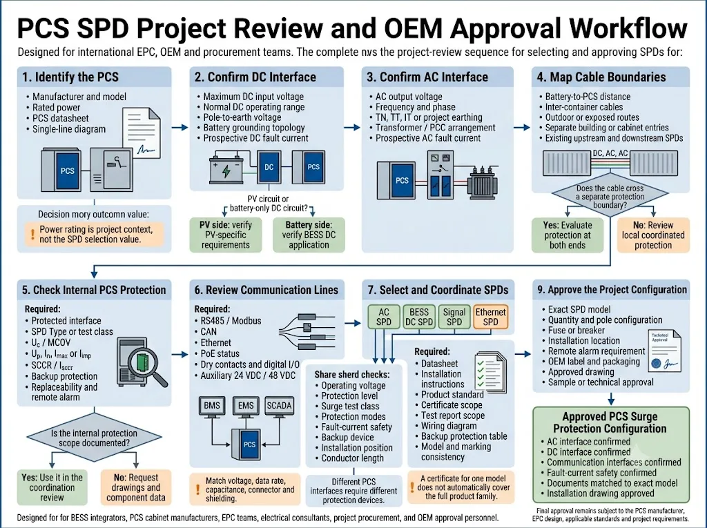
Mappare ogni interfaccia conduttiva
Elencare l'ingresso CC principale, la connessione CA, le alimentazioni ausiliarie, RS485, CAN, Ethernet, i contatti puliti, i sensori e i circuiti di emergenza. Identificare quali cavi escono dall'involucro collegato a terra.
Registrare i limiti operativi effettivi
Ottenere le informazioni sulla tensione CC massima, tensione CA, tensione polo-terra, tensione ausiliaria, tensione di segnale e sulla tenuta all'impulso dell'apparecchiatura.
Verificare la messa a terra e il collegamento a terra
Identificare il sistema di messa a terra CA, la topologia di messa a terra CC, il sistema di monitoraggio dell'isolamento, il metodo di schermatura dei cavi e la struttura di collegamento equipotenziale.
Identificare l'esposizione alle sovratensioni e i relativi confini
Esaminare l'LPS esterno, i percorsi esterni, la separazione dei contenitori, la lunghezza dei cavi e gli SPD a monte o a valle esistenti.
Verificare il coordinamento delle sovratensioni e dei guasti
Verificare Uc o MCOV, Up, classe di prova di sovratensione, modalità di protezione, corrente di guasto presunta, dispositivo di backup e coordinamento con altri SPD.
Completare l'approvazione tecnica
Confrontare i modelli e il cablaggio proposti con il manuale PCS, lo schema unifilare EPC, le norme applicabili e le specifiche di progetto prima di procedere all'ordine.
Come cambia la logica di protezione in base al layout del BESS
Batteria e PCS in un unico container
I percorsi di alimentazione interni possono essere brevi e rimanere all'interno di un unico involucro collegato. Verificare la protezione già installata in ogni ingresso esterno prima di aggiungere dispositivi duplicati.
Container separati per batteria e PCS
I cavi di comunicazione e CC esterni creano confini separati. Verificare entrambe le estremità dei cavi, l'esposizione del percorso, il collegamento equipotenziale e il coordinamento tra gli SPD locali.
PCS su scala industriale con trasformatore
Esaminare il terminale CA a bassa tensione del PCS, la disposizione del trasformatore, il quadro elettrico principale, la corrente di guasto disponibile, la protezione a monte e la progettazione contro il rischio di fulmini.
Progetto ibrido FV e BESS
Mantenere chiaramente separati le stringhe FV, i circuiti CC della batteria e le interfacce del convertitore. Non considerare ogni circuito da 1.500 VCC come la stessa applicazione SPD.
La norma IEC 62933-5-1:2024 fornisce considerazioni generali sulla sicurezza per i sistemi di accumulo di energia elettrica integrati nella rete. La norma IEC 62933-5-2:2025 aggiunge i requisiti di sicurezza per i sistemi di accumulo di energia elettrochimica durante tutto il loro ciclo di vita.[11][12]
Questi standard definiscono il contesto di sicurezza più ampio per i BESS. L'SPD specifico deve comunque essere selezionato utilizzando lo standard di prodotto pertinente per CA, CC o segnale e il progetto approvato.
Errori comuni nella protezione delle sovratensioni dei PCS
| Errore | Perché crea rischio | Migliori pratiche di progetto |
|---|---|---|
| Selezione basata esclusivamente sulla potenza del PCS | MW o kW non definiscono la tensione, la corrente di guasto, la messa a terra o l'esposizione | Raccogliere i dati elettrici specifici dell'interfaccia |
| Utilizzo di una categoria SPD ovunque | I circuiti in CA, in CC a batteria e di comunicazione presentano condizioni differenti | Selezionare ciascuna interfaccia separatamente |
| Trattamento automatico della CC della batteria come CC fotovoltaica | L'ambito di applicazione, il comportamento della sorgente e le condizioni di guasto possono variare | Verificare l'applicazione CC del BESS dichiarata |
| Supponendo che l'SPD interno copra tutto | Il dispositivo interno potrebbe proteggere solo un circuito o un terminale | Richiedere lo schema elettrico e i dati dei componenti |
| Protezione limitata alle sole linee di alimentazione | Una comunicazione o un transitorio ausiliario possono disabilitare il controller | Esaminare ogni conduttore instradato esternamente |
| Ignorare la corrente di guasto presunta | L'SPD o il dispositivo di backup potrebbero non eliminare un guasto in sicurezza | Verificare l'SCCR o l'Isccr e la protezione di backup |
| Utilizzo di connessioni SPD lunghe | L'induttanza di connessione aumenta la tensione che raggiunge il PCS | Utilizzare connessioni brevi e dirette e un collegamento equipotenziale adeguato |
Informazioni richieste prima di un ordine di SPD per PCS
Una raccomandazione utile richiede qualcosa di più di un semplice "BESS PCS" o "inverter da 1.500 V". Si prega di preparare i seguenti dati prima di richiedere un preventivo, un campione o una configurazione OEM.
Documenti da verificare prima dell'approvazione del modello
- Scheda tecnica del PCS e programma delle interfacce;
- Schemi unifilari AC e DC;
- dettagli del componente SPD interno o di protezione dalle sovratensioni;
- calcoli delle correnti di guasto presunte in CA e CC;
- scheda tecnica e istruzioni di installazione dell'SPD;
- ambito del certificato o del rapporto di prova specifico per il modello;
- tabella di coordinamento per fusibili di riserva o interruttori;
- disegno approvato della disposizione dell'armadio e del cablaggio.
Un certificato relativo a un modello non copre automaticamente ogni tensione, disposizione dei poli o modulo appartenente alla stessa famiglia di prodotti. Verificare la marcatura del modello, l'ambito del rapporto e la configurazione del progetto.
Inviare questi parametri al fornitore di SPD
LEEYEE può utilizzare questi dettagli per preparare una selezione di modelli e identificare le condizioni che richiedono ancora una conferma da parte del produttore del PCS, dell'integratore di sistema o dell'EPC.
CNSPD è la piattaforma di LEEYEE dedicata alla protezione dalle sovratensioni per gli acquirenti tecnici globali. L'approvazione finale del progetto rimane subordinata alla documentazione del PCS, agli standard applicabili e alla revisione tecnica responsabile.
Condividere i requisiti dell'interfaccia PCS
Inviare la scheda tecnica del PCS, l'intervallo di tensione CC, lo schema unifilare CA, i percorsi dei cavi, le interfacce di comunicazione, le correnti di guasto presunte e lo standard di progetto richiesto.
LEEYEE può esaminare i requisiti per CA, CC batteria, segnale, Ethernet, protezione di backup e allarme remoto prima che venga confermato un modello OEM o un campione di progetto.
Domande frequenti
Ogni PCS per BESS necessita di un SPD sia sul lato AC che su quello DC?
Entrambe le interfacce devono essere valutate, ma il numero e la posizione finali degli SPD dipendono dalla protezione interna del PCS, dal percorso dei cavi, dalla protezione a monte, dall'esposizione ai fulmini, dalla messa a terra, dal collegamento equipotenziale e dalle specifiche di progetto.
È possibile utilizzare un SPD DC per fotovoltaico all'ingresso batteria di un PCS?
Non dare per scontata l'idoneità basandosi esclusivamente sulla tensione nominale. Verificare che lo specifico prodotto sia dichiarato per l'applicazione DC su batteria, la topologia, la corrente di guasto e il metodo di disconnessione richiesto.
Un SPD di Tipo 2 è sufficiente per il lato CA del PCS?
Può essere appropriato in alcune posizioni di apparecchiature locali o di distribuzione, ma non rappresenta una soluzione universale. Il tipo di SPD richiesto dipende dal confine dell'installazione, dall'LPS, dalla protezione a monte e dalle normative di progetto applicabili.
È necessario installare un SPD sia sull'armadio batterie che sul PCS?
Valutare entrambe le estremità quando le apparecchiature sono separate da cavi esterni o esposti, oppure quando le estremità formano confini di protezione differenti. Un sistema compatto all'interno di un unico involucro equipotenziale può utilizzare una disposizione coordinata differente.
La potenza del PCS determina la capacità di scarica nominale dell'SPD?
No. La potenza del PCS e la capacità di scarica dell'SPD descrivono condizioni differenti. La scelta dell'SPD dipende dall'esposizione alle sovratensioni, dalla posizione di installazione, dalla classe di prova, dal coordinamento e dal rischio del progetto.
L'SPD interno al PCS può sostituire tutti gli SPD esterni?
Non è possibile stabilirlo senza documentazione. Verificare quale interfaccia protegge il dispositivo interno, le sue specifiche, la modalità di connessione, i limiti di coordinamento e se le apparecchiature remote rimangono al di fuori del suo raggio di protezione.
Un collegamento di comunicazione in fibra ottica necessita di un SPD per il segnale?
La fibra ottica in sé non conduce sovratensioni. È comunque necessario esaminare l'alimentatore associato, il convertitore di media, l'armatura metallica, il cavo patch Ethernet e altre connessioni conduttive.
Quali informazioni sono fondamentali per un preventivo relativo a un SPD CC per PCS?
Fornire la tensione CC massima, l'intervallo operativo, la configurazione di messa a terra, la tensione polo-terra, la corrente di guasto presunta, il percorso dei cavi, la posizione di installazione e la protezione esistente.
È opportuno selezionare un SPD di segnale basandosi esclusivamente sul nome del protocollo?
No. Il solo nome del protocollo non è sufficiente. Verificare la tensione di esercizio, la tensione di modo comune, la velocità di trasmissione dati, la capacità, il connettore, la schermatura e la configurazione di messa a terra.
Riferimenti
- Commissione Elettrotecnica Internazionale, IEC 62909-1:2025, Convertitori di potenza bidirezionali collegati alla rete — Parte 1: Requisiti generali e di sicurezza. Pagina ufficiale della pubblicazione IEC.
- Commissione Elettrotecnica Internazionale, IEC 62477-1:2022, Requisiti di sicurezza per sistemi e apparecchiature di conversione di potenza — Parte 1: Generale. Pagina ufficiale della pubblicazione IEC.
- Commissione Elettrotecnica Internazionale, IEC 61643-01:2024, Dispositivi di protezione contro le sovratensioni a bassa tensione — Parte 01: Requisiti generali. Pagina ufficiale della pubblicazione IEC.
- Commissione Elettrotecnica Internazionale, IEC 61643-11:2025, Dispositivi di protezione contro le sovratensioni a bassa tensione — Parte 11: Dispositivi di protezione contro le sovratensioni collegati a sistemi di alimentazione a bassa tensione in corrente alternata — Requisiti e metodi di prova. Pagina ufficiale della pubblicazione IEC.
- Commissione Elettrotecnica Internazionale, IEC 61643-12:2020, Dispositivi di protezione contro le sovratensioni a bassa tensione — Parte 12: Dispositivi di protezione contro le sovratensioni collegati a sistemi di alimentazione a bassa tensione — Principi di selezione e applicazione. Pagina ufficiale della pubblicazione IEC.
- Commissione Elettrotecnica Internazionale, IEC 61643-41:2025, Scaricatori di sovratensione a bassa tensione — Parte 41: Scaricatori di sovratensione collegati a sistemi di alimentazione CC a bassa tensione — Requisiti e metodi di prova. Pagina ufficiale della pubblicazione IEC.
- Commissione Elettrotecnica Internazionale, IEC 61643-31:2018, Scaricatori di sovratensione a bassa tensione — Parte 31: Requisiti e metodi di prova per scaricatori di sovratensione (SPD) per impianti fotovoltaici. Pagina ufficiale della pubblicazione IEC.
- Commissione Elettrotecnica Internazionale, IEC 61643-21:2025, Scaricatori di sovratensione a bassa tensione — Parte 21: Scaricatori di sovratensione collegati a reti di telecomunicazione e segnalazione — Requisiti e metodi di prova. Pagina ufficiale della pubblicazione IEC.
- Commissione Elettrotecnica Internazionale, IEC 61643-22:2015, Dispositivi di protezione contro le sovratensioni a bassa tensione — Parte 22: Dispositivi di protezione contro le sovratensioni collegati a reti di telecomunicazione e di segnalazione — Principi di selezione e applicazione. Pagina ufficiale della pubblicazione IEC.
- Commissione Elettrotecnica Internazionale, IEC 62305-4:2024, Protezione contro i fulmini — Parte 4: Sistemi elettrici ed elettronici all'interno di strutture. Pagina ufficiale della pubblicazione IEC.
- Commissione Elettrotecnica Internazionale, IEC 62933-5-1:2024, Sistemi di accumulo di energia elettrica — Parte 5-1: Considerazioni sulla sicurezza per i sistemi di accumulo di energia (EES) integrati nella rete — Specifica generale. Pagina ufficiale della pubblicazione IEC.
- Commissione Elettrotecnica Internazionale, IEC 62933-5-2:2025, Sistemi di accumulo di energia elettrica — Parte 5-2: Requisiti di sicurezza per i sistemi di accumulo di energia (EES) integrati nella rete — Sistemi basati su tecnologie elettrochimiche. Pagina ufficiale della pubblicazione IEC.
- ABB, Commutazione e protezione del bus a 1500 V CC nei sistemi di conversione di potenza, nota applicativa riguardante i sistemi di conversione di potenza (PCS) utilizzati in applicazioni fotovoltaiche, BESS e a idrogeno. Nota applicativa ufficiale ABB.
