Need a three-phase SPD wiring diagram for a distribution board, control panel, or OEM electrical cabinet?
The key point is simple: a three-phase SPD is not selected only by counting wires. It must match the earthing system, system voltage, pole configuration, installation position, and backup protection.
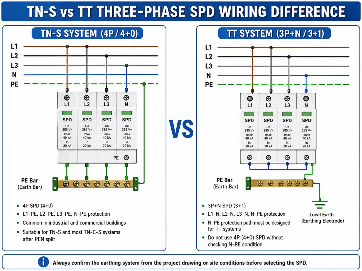
For many TN-S and TN-C-S three-phase panels, the SPD is commonly wired between L1, L2, L3, N and PE. For TT systems, a 3+1 or 3P+N connection is often used because the neutral-to-earth relationship is different.
Nota de seguridad: This guide explains three-phase SPD wiring logic for selection, panel design, and technical communication. Final installation should follow the local electrical code, project drawings, and the SPD datasheet, and should be completed by qualified electrical personnel.
Índice
Quick Answer: How Is a Three-Phase SPD Wired?
In a typical three-phase distribution board, the SPD is installed near the incoming supply and connected to the phase conductors, neutral conductor, and protective earth.
A common three-phase SPD wiring diagram includes L1, L2, L3, N and PE. The SPD earth terminal should be connected to the PE bar with a short and direct conductor.
The correct wiring mode depends mainly on the earthing system. TN-S systems commonly use 4P or 4+0 wiring. TT systems often use 3P+N or 3+1 wiring.
| Tipo de sistema | Common SPD Wiring Logic | Common SPD Configuration | Nota del Comprador |
|---|---|---|---|
| TN-S | L1, L2, L3 and N protected to PE | 4P / 4+0 | Common for industrial and commercial distribution boards. |
| TN-C-S | After PEN splits into N and PE, wire according to the panel design | 4P or 3P+N | Confirm where PEN is separated before choosing the SPD. |
| TT | L1, L2 and L3 protected to N; N protected to PE | 3P+N / 3+1 | Do not blindly use 4+0 without checking the N-PE condition. |
| 3-phase 3-wire | L1, L2 and L3 protected to PE | 3P | Used when neutral is not available at the protection point. |
| IT | Project-specific design required | Usually project-specific | Confirm with the electrical design before ordering. |
The image below is a three-phase SPD wiring diagram for a TN-S distribution panel. It shows the typical relationship between the incoming supply, main switch, SPD backup protection, 4P SPD, PE bar, and downstream equipment.
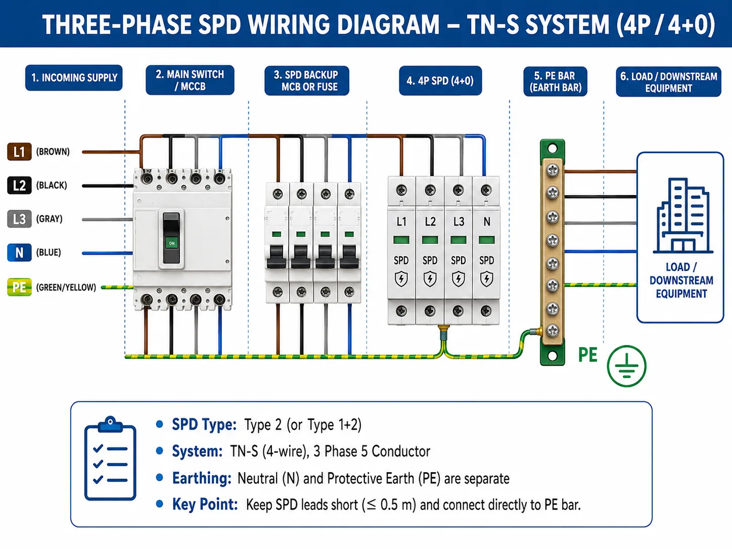
Importante: A wiring diagram should not only show the SPD module. It should also show the incoming supply, main switch, backup MCB or fuse, PE bar, load direction, and earthing system.
Basic Three-Phase SPD Wiring Steps
The exact wiring must follow the project drawing and SPD datasheet. But for selection and panel design, the basic three-phase surge protector wiring process usually follows these steps.
What Does a Three-Phase SPD Wiring Diagram Show?
A useful three-phase SPD wiring diagram should show how surge current is discharged safely to earth. It should not be only a decorative product image.
A complete diagram should show:
- Incoming supply: L1, L2, L3, N and PE
- Main switch, MCCB, MCB or fuse
- SPD installation position
- SPD pole configuration
- PE bar connection
- Load side direction
- Sistema de conexión a tierra
- Protección de respaldo
This matters because an SPD does not work like a normal circuit breaker. A circuit breaker protects against overload and short circuit. An SPD protects against transient overvoltage.
The SPD must provide a short path for surge current to discharge to earth. If the wiring is too long, loose, or connected to the wrong reference point, the downstream equipment may still see a high voltage spike.
Three-Phase SPD Wiring Diagram for TN-S Systems
In a TN-S system, neutral and protective earth are separate conductors. A typical three-phase TN-S panel has L1, L2, L3, N and PE.
In many TN-S distribution boards, a 4P SPD or 4+0 connection is used. Each conductor is protected with a discharge path to PE.
| Conductor | SPD Connection | Propósito |
|---|---|---|
| L1 | L1 terminal of SPD | Phase surge protection path |
| L2 | L2 terminal of SPD | Phase surge protection path |
| L3 | L3 terminal of SPD | Phase surge protection path |
| N | N terminal of SPD | Neutral surge protection path |
| PE | Earth terminal of SPD to PE bar | Discharge path to earth |
The SPD should be installed close to the incoming side and close to the PE bar. This reduces cable length and improves the actual protection level inside the panel.
For OEM panel builders, this point is important. A neat-looking installation is not always a good installation. If SPD wires are routed around the cabinet only for appearance, the total lead length may become too long.
Three-Phase SPD Wiring Diagram for TN-C-S Systems
TN-C-S systems need extra attention. In a TN-C-S system, the supply side may use a combined PEN conductor. At a certain point, PEN is separated into N and PE.
The SPD should be selected and wired according to the position where this separation happens.
Before choosing the SPD for TN-C-S, confirm:
- Is the SPD installed before or after PEN separation?
- Does the panel have separate N and PE bars?
- Is the neutral conductor present at the SPD installation point?
- What does the project drawing specify?
- What does the local electrical code require?
If the SPD is installed after PEN has already split into N and PE, the wiring may look similar to a TN-S panel. But do not assume this by appearance only.
For TN-C-S systems, the installation point matters. This is why buyers should send the panel wiring diagram to the SPD supplier before confirming the model.
Three-Phase SPD Wiring Diagram for TT Systems
In a TT system, the installation has its own local earth electrode. The neutral and protective earth relationship is different from a TN-S system.
For this reason, TT systems often use a 3+1 or 3P+N SPD configuration.
The common wiring logic is:
- L1 to N
- L2 to N
- L3 to N
- N to PE through a dedicated N-PE protection path
This design helps avoid applying the wrong protection logic between neutral and earth. A TT system should not be treated the same as a TN-S system only because both may have L1, L2, L3, N and PE conductors in the panel.
The number of wires is not enough. The earthing system decides the SPD connection logic.
The following TN-S vs TT SPD wiring diagram compares 4P / 4+0 wiring with 3P+N / 3+1 wiring. This comparison is especially useful for three-phase distribution boards, TT systems, and OEM electrical cabinet selection.
3P vs 4P vs 3P+N SPD Wiring
Many wiring mistakes happen because buyers choose SPD poles only by looking at the panel. This is risky.
A three-phase system may use 3P, 4P, or 3P+N SPD depending on the wiring and earthing design.
| SPD Configuration | Uso Típico | Wiring Meaning | Nota importante |
|---|---|---|---|
| 3P SPD | Three-phase 3-wire systems | L1, L2 and L3 protection | Used where neutral is not present. |
| 4P SPD | Three-phase 4-wire TN-S or similar systems | L1, L2, L3 and N protection to PE | Common in many distribution boards. |
| 3P+N SPD | TT systems or 3+1 protection design | L1/L2/L3 to N, N to PE | Do not replace blindly with ordinary 4P. |
| Type 1+2 3-phase SPD | Main incomer or high exposure panels | Lightning impulse and surge protection | Check Iimp, In and backup fuse. |
| Type 2 3-phase SPD | Sub-distribution or standard panels | Surge protection for downstream equipment | Common for industrial control panels. |
A 3P SPD does not automatically mean “three-phase SPD for all three-phase panels.” A 4P SPD does not automatically mean “better than 3P+N.”
The right choice depends on earthing system, neutral availability, SPD type, panel position, system voltage, required standard, backup protection, and OEM design requirement.
Where Should the SPD Be Installed in a Three-Phase Panel?
For most three-phase AC panels, the SPD is installed near the incoming supply side.
Common installation positions include:
- Cuadro de distribución principal
- Cuadro de subdistribución
- Gabinete de control industrial
- Machine control panel
- Commercial building distribution box
- PV inverter AC output panel
- OEM electrical cabinet
In many panels, the SPD is placed after the main switch or main breaker, with a dedicated backup MCB or fuse. The exact position depends on the panel design and local electrical requirements.
The key rule is simple: the SPD must have a short and low-impedance path to PE.
Does a Three-Phase SPD Need a Circuit Breaker or Fuse?
Yes, in most installations, the SPD should have suitable upstream overcurrent protection. This may be an MCB, MCCB, or fuse.
Backup protection is not used to stop surges. It is used to disconnect the SPD safely if the SPD reaches end of life or fails short-circuit.
The backup fuse or breaker rating should follow the SPD datasheet. Do not select the backup protection only by habit.
Before ordering, confirm: maximum backup fuse rating, short-circuit current rating, SPD type, system voltage, expected fault current, panel main breaker rating, and local installation standard.
Lead Length: Why Short SPD Wiring Matters
SPD wires should be as short and direct as possible.
During a surge, current rises very fast. Long wires add inductance. This increases the voltage seen by the equipment even when the SPD itself is working.
That means a high-quality SPD can perform poorly if it is installed with long leads.
Common Three-Phase SPD Wiring Mistakes
Three-phase SPD wiring problems often look small in the cabinet, but they can reduce the actual protection effect. The following diagram highlights common three-phase surge protector wiring mistakes seen in distribution boards and control panels.
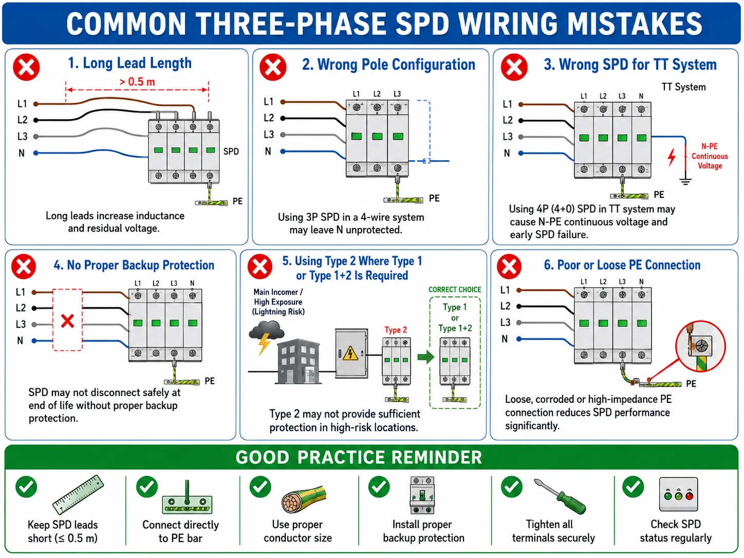
1. Choosing SPD by pole count only
Some buyers choose 3P, 4P, or 3P+N only by counting the wires in the cabinet. This is not enough. The earthing system and connection mode must be confirmed.
2. Using 4P SPD blindly in TT systems
TT systems often require 3+1 protection logic. If the N-PE condition is not considered, the SPD may age faster or fail early.
3. Long PE connection
A long PE wire can reduce real protection performance. The SPD may still look correctly installed, but downstream equipment may see higher residual voltage.
4. No proper backup protection
Some installations skip the SPD backup MCB or fuse to save space. This is not recommended. The SPD needs a safe disconnection path if it fails at end of life.
5. Wrong Type 1 and Type 2 position
Type 2 SPD is common for sub-distribution boards. If the installation is at the main incoming point with high exposure, Type 1 or Type 1+2 may be required.
6. Poor PE connection
The PE path is the discharge path. A loose PE terminal, damaged conductor, corroded connection, or poor earth bar connection can make the SPD much less effective.
Before Ordering a Three-Phase SPD, Confirm These Details
Before asking for a quotation, prepare these details. This helps the supplier recommend the correct SPD model faster.
| Information to Confirm | Por qué es Importante |
|---|---|
| Nominal system voltage | Determines Uc and SPD voltage rating. |
| System type | TN-S, TN-C-S, TT, IT, or 3-phase 3-wire. |
| Pole configuration | Determines whether 3P, 4P, or 3P+N is suitable. |
| SPD type | Type 1, Type 2, or Type 1+2. |
| Installation position | Main incomer, sub-board, control panel, or OEM cabinet. |
| In / Imax / Iimp requirement | Determines discharge capacity. |
| Backup fuse or MCB | Required for safe coordination. |
| Neutral availability | Affects 3P, 4P, and 3P+N selection. |
| Remote signal requirement | Needed for monitoring and maintenance. |
| Certification requirement | CE, TUV, CB, or project-specific documents. |
| OEM label requirement | Important for distributors and panel builders. |
Need Help Choosing the Right Three-Phase SPD?
Send us your system voltage, earthing type, panel photo, and wiring diagram. Our team can recommend a suitable SPD configuration for distribution board or OEM panel orders.
Recommended Three-Phase SPD Selection Logic
- Confirm the system voltage. For example: 230/400V, 380/400V, or 400/415V.
- Confirm the earthing system. TN-S, TN-C-S, TT and IT systems may require different wiring logic.
- Confirm whether neutral is present. A three-phase 3-wire system may use 3P. A three-phase 4-wire system may use 4P or 3P+N depending on the earthing design.
- Confirm the installation position. Main incoming panels may need Type 1 or Type 1+2. Sub-distribution boards commonly use Type 2.
- Confirm surge current requirement. Check In, Imax, or Iimp according to project requirements.
- Confirm backup protection. Use the backup fuse or breaker rating recommended in the SPD datasheet.
- Confirm maintenance needs. If the panel needs remote alarm, choose an SPD with remote signal contact.
PREGUNTAS FRECUENTES
What is the correct wiring for a three-phase SPD?
A three-phase SPD is usually connected to L1, L2, L3, N if present, and PE. The exact wiring depends on the earthing system and SPD configuration. TN-S systems commonly use 4P or 4+0 wiring, while TT systems often use 3P+N or 3+1 wiring.
How do I wire a 3 phase surge protector?
First confirm the system voltage, earthing system, neutral availability, and SPD configuration. Then connect L1, L2, L3, N if required, and PE according to the wiring mode shown in the SPD datasheet. The SPD earth terminal should connect directly to the PE bar with a short conductor.
Is 3P SPD enough for a three-phase system?
A 3P SPD may be suitable for a three-phase 3-wire system without neutral. If the panel has neutral and requires neutral protection, 4P or 3P+N may be needed. Do not choose only by the words “three phase.”
What is the difference between 4P and 3P+N SPD?
A 4P SPD commonly protects L1, L2, L3 and N to PE. A 3P+N SPD usually follows 3+1 protection logic, where the three phases are protected to neutral and neutral is protected to PE. The correct choice depends on the earthing system.
What does 3+1 SPD wiring mean?
3+1 SPD wiring usually means L1, L2 and L3 are protected to neutral, and neutral is protected to PE through a dedicated N-PE protection path. This connection is often used in TT systems.
Can I use a 4P SPD in a TT system?
Do not use a 4P SPD in a TT system without checking the wiring design and product suitability. TT systems often use 3+1 or 3P+N SPD configuration because the N-PE relationship is different from TN-S systems.
Where should a three-phase SPD be installed?
A three-phase SPD is usually installed near the incoming side of a distribution board or control panel, close to the PE bar. The connection path should be short and direct.
Does a three-phase SPD need a backup fuse or MCB?
In most installations, yes. The backup fuse or MCB helps disconnect the SPD safely if it fails at end of life. The rating should follow the SPD datasheet.
What happens if the SPD earth wire is too long?
Long SPD wiring increases inductance and can increase the residual voltage seen by downstream equipment. The SPD may still work, but the actual protection effect becomes weaker.
What information should I send before ordering a three-phase SPD?
Send the system voltage, earthing system, pole requirement, installation position, panel wiring diagram, backup fuse requirement, certification requirement, and whether remote signal contact is needed.