
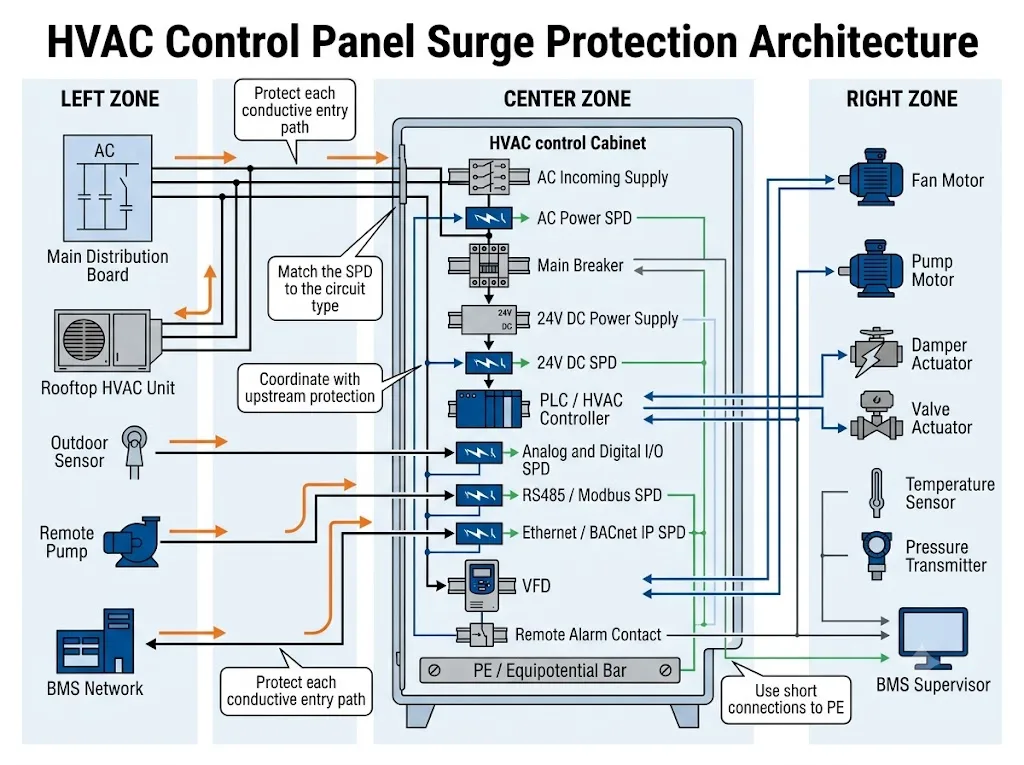
HVAC control panel surge protection is not limited to installing one AC surge protective device at the panel incomer. A commercial or industrial HVAC cabinet may connect three-phase power, 24V DC controls, VFDs, pumps, fans, sensors, actuators, RS485 networks and Ethernet-based building management systems.
Each connection creates a different possible surge path. The correct protection concept begins by identifying every conductive cable that enters or leaves the cabinet, then matching the SPD to the electrical characteristics, installation position and exposure of that circuit.
Alcance de la página: This guide focuses on HVAC-specific equipment such as AHUs, chillers, cooling towers, rooftop units, BMS interfaces, fans and pumps. For general PLC, machine and automation cabinets, use the industrial control panel surge protection guide.
Índice
Respuesta Rápida
An HVAC control panel should be assessed as a group of separate power, control and communication interfaces. Protect the incoming AC supply first. Then assess exposed 24V DC, sensor, actuator, RS485, Modbus, BACnet and Ethernet cables individually.
- AC incoming supply: coordinate the panel SPD with the building’s upstream protection.
- 24V DC controls: confirm maximum operating voltage, current, polarity and grounding reference.
- Analog and digital I/O: check signal range, leakage, series resistance and conductor arrangement.
- BMS communication: identify the physical interface before selecting the protector.
- Rooftop or remote equipment: assess cable entry points, both cable ends and equipotential bonding.
Does an HVAC Control Panel Need an SPD?
The word “HVAC” alone does not determine whether a particular SPD is required. The decision depends on the building electrical design, transient exposure, cable routing, upstream protection, equipment sensitivity and consequences of an HVAC shutdown.
Modern HVAC panels contain electronic controllers, switch-mode power supplies, communication interfaces and variable-frequency drives. A transient entering through either a power cable or a field signal cable may damage equipment or interrupt ventilation, cooling, pumping or BMS communication.
IEC 60364-4-44 addresses protection of low-voltage installations against voltage and electromagnetic disturbances. IEC 60364-5-53 and IEC 61643-12 provide principles for selecting, locating and coordinating SPDs in low-voltage power systems.[1][2][3]
Do not begin with “Which HVAC SPD model should I buy?” Begin with “Which power, control and communication cables connect this HVAC panel to the building and to exposed field equipment?”
Which Surge Entry Paths Should Be Checked?
A control cabinet may have more surge entry paths than its three-phase incomer. Leaving one exposed control or communication interface unassessed may allow a transient to reach the same controller that the AC SPD is intended to protect.
The circuit type is more important than the general description “HVAC cable.”
| Possible Entry Path | Typical HVAC Connection | What Must Be Confirmed | Protection Direction |
|---|---|---|---|
| Incoming AC power | Single-phase or three-phase panel supply | System voltage, earthing system, upstream SPD, panel position and short-circuit conditions | Coordinated Type 1, Type 1+2 or Type 2 power SPD |
| 24V DC power | PLC, relay, actuator or remote I/O supply | Maximum DC voltage, current, polarity, common reference and permitted voltage drop | DC power or combined power-and-signal SPD |
| Señal analógica | 0–10V, 4–20mA, pressure or temperature transmitter | Signal range, loop voltage, resistance, leakage and measurement accuracy | Low-leakage signal SPD matched to the loop |
| E/S Digital | Start, stop, alarm, status, valve or damper control | Dry contact, powered input, relay output, transistor output and shared common | Circuit-specific control-line SPD |
| Serial communication | RS485, Modbus RTU or BACnet MS/TP | Wire count, signal reference, baud rate, capacitance, shield and termination | RS485-compatible signalling SPD |
| Ethernet communication | Modbus TCP, BACnet/IP or supervisory gateway | Network speed, cable category, connector, shielding and PoE | Ethernet or PoE SPD where exposure justifies it |
| Remote equipment cable | Rooftop AHU, condenser, cooling tower, pump or outdoor sensor | Cable route, protection-zone boundary, bonding, earth reference and equipment at both ends | Protection at the relevant entry point and possibly both ends |
Procurement conclusion: one HVAC panel may require one AC SPD and several different DC or signal SPDs. These devices cannot be selected from one common voltage, pole count or discharge-current value.
How Should the HVAC Main Power Circuit Be Protected?
The incoming power supply is normally the first circuit to review. The appropriate SPD classification depends on the panel’s position within the building distribution system and on the surge stress expected at that position.
A Type 2 SPD is commonly evaluated for an indoor HVAC control panel installed downstream of coordinated building-level protection. Type 1 or Type 1+2 protection may need to be considered closer to the service entrance or where the design expects partial lightning current.
This is a project-dependent selection direction, not a universal rule based only on whether the cabinet is indoors or outdoors. The supply arrangement, external lightning-protection system, risk assessment, upstream SPD and applicable local requirements must be reviewed together.[2][3][4]
| HVAC Panel Position | Typical Starting Direction | What Must Still Be Verified |
|---|---|---|
| Indoor cabinet supplied from a protected sub-board | Evaluate a coordinated Type 2 SPD at the panel incomer | Cable distance, upstream SPD, Up, equipment withstand and short-circuit conditions |
| Main mechanical-services switchboard | Review whether Type 1, Type 1+2 or Type 2 applies | Service position, external LPS, lightning-current exposure and supply configuration |
| Remote plant room or separate structure | Evaluate additional protection at the remote distribution entry | Feeder route, bonding, earthing arrangement and protection at both structures |
| Rooftop or outdoor HVAC cabinet | Assess coordinated local AC protection near the equipment | Cable entry, rooftop bonding, upstream protection and enclosure arrangement |
AC Power SPD Parameters to Confirm
- Nominal system voltage: for example 230/400V or 240/415V.
- Maximum continuous operating voltage, Uc: matched to the real supply and protection mode.
- Earthing arrangement: TN-S, TN-C-S, TT or another system.
- Number of conductors and poles: including whether a neutral conductor is present.
- SPD classification: Type 1, Type 1+2 or Type 2.
- Discharge parameters: Iimp, In and Imax as applicable.
- Voltage protection level, Up: coordinated with the impulse withstand of downstream equipment.
- Prospective short-circuit current: checked against the SPD capability and backup-protection arrangement.
- Maximum backup fuse or MCB: taken from model-specific manufacturer documentation.
- Remote indication: required when the BMS must report loss of protection.
A high discharge-current rating does not correct the wrong Uc, protection mode, Up, short-circuit capability, backup protective device or installation position.
A model-specific page should state the pole arrangement, Uc, Up, In or Iimp, short-circuit conditions, maximum backup protection, conductor range, dimensions and remote-contact option.
For example, the LEEYEE LY1-C40/3(S) three-pole Type 2 SPD documents parameters relevant to three-phase control-panel applications. It is an example of the required verification process, not an automatic recommendation for every HVAC cabinet.
How Should 24V DC, Sensors and Control I/O Be Protected?
The AC SPD protects the input side of the panel power supply. It does not automatically protect every 24V DC cable connected to the power-supply output.
Additional DC or signal protection becomes more relevant when a circuit leaves the cabinet, supplies rooftop equipment, connects a remote actuator or carries measurements from outdoor sensors.
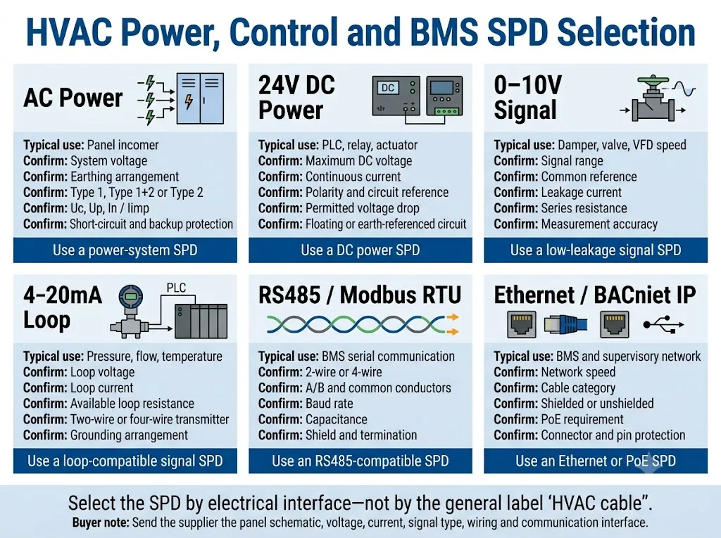
The nominal description “24V DC” is not enough for model selection. The supplier also needs the maximum normal voltage, continuous current, conductor function, circuit reference and allowable voltage drop.
| Interfaz | Typical HVAC Use | Parameters That Matter | Wrong-Selection Risk |
|---|---|---|---|
| 24V DC power | PLC, relay, actuator or remote I/O supply | Maximum voltage, continuous current, polarity, reference and voltage drop | Overloaded SPD, excessive voltage drop or incomplete conductor protection |
| 0–10V | Damper, valve or VFD speed reference | Signal range, common reference, leakage and series resistance | Incorrect command value or unstable control |
| 4–20mA | Pressure, flow or temperature transmitter | Loop voltage, available resistance, wiring method and grounding | Excessive loop burden or measurement error |
| E/S Digital | Run status, alarm, valve, damper or contactor command | Dry contact or powered signal, relay or transistor output and shared common | False indication, nuisance operation or output damage |
| RTD or thermistor | Medición de temperatura | Sensor type, wire count, measuring current and permissible added resistance | Temperature offset or controller error |
Conclusión de ingeniería: a signal SPD must pass the normal measurement or command without unacceptable leakage, resistance, capacitance or distortion while limiting the transient voltage.
For detailed field-interface selection, see the PLC I/O signal surge protection guide.
How Should BMS, RS485, Modbus and BACnet Lines Be Protected?
The protocol name does not always identify the required SPD. The physical electrical interface must also be confirmed.
Modbus is an application-layer protocol that may operate over different networks. Modbus RTU is commonly carried over an EIA/TIA-485 serial network, while Modbus TCP uses TCP/IP, commonly over Ethernet.[8][9]
BACnet MS/TP uses an EIA-485 physical layer. BACnet/IP is an IP-based transport and should not automatically be treated as the same electrical interface as MS/TP.[10]
| BMS Description | Typical Physical Interface | SPD Selection Checks | Common Purchasing Error |
|---|---|---|---|
| Modbus RTU | Usually two-wire or four-wire RS485 | A/B or D0/D1 conductors, common, baud rate, capacitance and shield | Ordering from the word “Modbus” without confirming the serial wiring |
| Modbus TCP | TCP/IP, commonly Ethernet | Network speed, cable category, connector, shielding and PoE | Installing an RS485 protector on an Ethernet port |
| BACnet MS/TP | EIA-485 twisted-pair serial network | Topology, conductor reference, termination, shield and data rate | Adding excessive capacitance or disturbing bus impedance |
| BACnet/IP | IP-based network, often Ethernet | Actual physical medium, port type, speed, shielding and PoE | Protecting only the controller power supply |
| Proprietary controller bus | Manufacturer-specific | Pinout, signal voltage, data rate, cable and manufacturer approval | Assuming it is electrically identical to RS485 |
IEC 61643-21 applies to SPDs connected to telecommunications and signalling networks, including lines that may carry power such as PoE. IEC 61643-22 addresses selection, location and coordination principles for signalling-network SPDs.[6][7]
Surge protection does not correct unsuitable topology, incorrect termination, excessive stubs, wrong biasing or inappropriate shield treatment. Communication design and surge protection must both be reviewed.
Why Are Rooftop Equipment and Long HVAC Cables Higher Risk?
Rooftop AHUs, cooling towers, outdoor condensers, weather sensors and remote pumps may be connected to the control panel through long power, control and communication cables.
These conductors can be exposed to induced transient voltages. They may also connect equipment located at different local earth potentials, especially when the cable crosses between buildings or protection zones.
The project assessment should consider:
- whether the cable leaves the building or connects separate structures;
- whether the route is close to lightning down-conductors or exposed metalwork;
- whether both ends contain sensitive electronic equipment;
- whether the field equipment and control panel share an equipotential bonding system;
- how cable shields or armour are terminated;
- whether the route crosses a lightning-protection-zone boundary;
- whether power and communication cables reach the same remote equipment.
Protection may be required at the panel entry, at the remote equipment or at both ends. The final arrangement should follow the cable route, protection-zone boundaries and earthing system rather than an unsupported cable-length rule.[5][7]
An IP-rated enclosure can provide a defined level of protection against environmental ingress. It does not prevent a transient voltage from entering through a connected power or signal cable.
What Changes When the Panel Contains VFDs, Fans or Pumps?
HVAC control panels often operate supply fans, extract fans, chilled-water pumps, condenser pumps and compressors through contactors, soft starters or variable-frequency drives.
Protect the VFD Line Side as Part of the AC System
The incoming side of the VFD should be assessed as part of the panel’s AC surge-protection concept. The SPD must match the supply voltage, earthing arrangement, expected transient environment and drive manufacturer’s instructions.
Do Not Assume a Mains SPD Is Suitable for the VFD Output
A VFD output is a pulse-width-modulated waveform rather than a normal sinusoidal mains supply. Schneider Electric advises against installing a surge suppressor on the load side of the referenced variable-speed drives because the PWM output can damage the suppressor components.[11]
Motor-terminal peak voltage, reflected-wave effects and high dV/dt are normally addressed through the drive and motor manufacturer’s recommended cable, output reactor, dV/dt filter or sine-wave filter. The approved method must be confirmed for the specific drive and motor.
Assess VFD Control Interfaces Separately
A VFD may also connect to 24V digital I/O, 0–10V, 4–20mA, RS485, BACnet or Ethernet. These interfaces need separate assessment when their cables leave the cabinet or connect exposed equipment.
Ver el VFD surge protection guide for a focused comparison of drive input, output and communication-side risks.
How Should Protection Be Coordinated Inside the HVAC Panel?
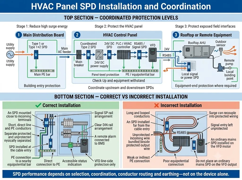
Coordinated HVAC surge protection means reviewing the building entry, distribution board, HVAC panel and exposed field interfaces as connected stages rather than as isolated products.
- Confirm the building-level protection Identify the SPDs installed in the main switchboard and mechanical-services distribution board.
- Confirm the HVAC panel position Establish whether it is a main mechanical board, downstream cabinet, rooftop unit or remote panel.
- Select the incoming AC SPD Match the supply voltage, earthing arrangement, protection mode, short-circuit conditions and upstream coordination.
- List every external control cable Include 24V power, analog I/O, digital I/O, RS485, Ethernet, sensors, actuators and remote alarms.
- Select interface-specific protection Use separate AC, DC or signalling devices according to the actual electrical interface.
- Check installation and maintenance Control conductor routing and provide access to indicators, replaceable modules and remote contacts.
IEC 61643-12 addresses selection, operation, location and coordination principles for SPDs connected to low-voltage power systems. Signalling circuits require separate consideration under IEC 61643-22.[3][7]
Why Do Earthing and Equipotential Bonding Matter?
An SPD diverts surge current through a defined connection path. The voltage that reaches the HVAC controller depends not only on the SPD’s published Up but also on the inductive voltage created by its connecting conductors.
Long, looped or poorly bonded conductors can increase the effective voltage seen by the protected equipment. A technically suitable SPD may therefore provide poor field performance when the connection path is unsuitable.
- Keep SPD connection conductors short and direct.
- Use the conductor cross-sectional area required by applicable rules and manufacturer instructions.
- Provide a clearly defined PE or equipotential bonding point.
- Bond the cabinet enclosure, door and relevant nearby metal structures.
- Follow the control-system manufacturer’s shield-treatment requirements.
- Separar los cables protegidos y no protegidos.
- Avoid unnecessary conductor loops.
IEC 60364-5-54 covers earthing arrangements, protective conductors and protective bonding conductors. IEC 62305-4 addresses surge-protection measures for electrical and electronic systems within structures.[5][12]
“Keep the connection short” does not mean using an undersized or mechanically unsafe conductor. Cross-section, insulation, routing and fault protection must comply with project requirements and device instructions.
HVAC Surge Protection Application Examples
These examples provide starting directions for engineering review. They are not fixed bills of materials.
| HVAC Application | Important Surge Paths | Protection Review | Buyer Must Provide |
|---|---|---|---|
| Indoor AHU control panel | AC incomer, controller power and external sensors | Coordinate the panel AC SPD and assess field I/O leaving the cabinet | Supply voltage, upstream SPD, controller voltage and I/O list |
| Rooftop HVAC cabinet | Exposed feeder, rooftop bonding, BMS cable and weather sensors | Assess power and signal entry points at the rooftop protection-zone boundary | Cable route, external LPS, earthing and panel location |
| Chiller plant with VFDs | Three-phase incomer, VFD inputs, PLC I/O and BMS communication | Protect line-side power and assess exposed control interfaces | VFD models, line voltage, control interfaces and motor-cable data |
| Cooling tower or remote pump | Outdoor feeder, pressure or level signals and RS485 | Assess both equipment ends and possible earth-potential differences | Distance, cable type, sensor loop and bonding arrangement |
| OEM packaged HVAC unit | Destination-market power, controller supply and optional BMS ports | Define configurable AC, DC and signal-protection options | Market, voltage, schematic, interfaces, required documents and quantity |
Significado para el comprador: the same packaged HVAC unit may require a different SPD configuration for an indoor commercial building, an exposed rooftop project or an industrial site with long external field wiring.
Common HVAC Control Panel Surge Protection Mistakes
Protecting Only the Incoming Three-Phase Supply
The AC SPD may be correctly selected while an outdoor RS485, 24V or analog cable remains directly connected to the controller.
Using One SPD Specification for Every Circuit
AC power, 24V DC, 0–10V, 4–20mA, digital I/O, RS485 and Ethernet have different electrical and transmission requirements.
Ignoring Upstream Protection
The HVAC panel SPD should be coordinated with the main and sub-distribution protection rather than selected as an isolated product.
Ordering a “Modbus SPD” Without Confirming the Interface
Modbus RTU and Modbus TCP normally require different physical protection devices.
Installing Long or Looped SPD Conductors
Added conductor inductance can increase the voltage reaching the protected controller.
Assuming an Ordinary Mains SPD Is Suitable for the VFD Output
The PWM output waveform may be unsuitable for a conventional mains SPD. Confirm output-side protection or filtering with the drive manufacturer.
What Should Buyers Confirm Before Ordering?
- panel input voltage and frequency;
- single-phase or three-phase supply;
- earthing arrangement;
- panel position within the building distribution system;
- existing upstream Type 1, Type 1+2 or Type 2 SPD;
- prospective short-circuit current;
- required AC protection mode and pole configuration;
- 24V DC maximum voltage and load current;
- analog signals such as 0–10V, 4–20mA, RTD or thermistor;
- digital I/O type and shared common conductors;
- Modbus RTU, Modbus TCP, BACnet MS/TP, BACnet/IP or another interface;
- RS485 wire count, reference conductor, shield and baud rate;
- Ethernet category, network speed, shielding and PoE requirement;
- outdoor and rooftop equipment locations;
- external power, control and communication cable routes;
- VFD brand, model and connected control interfaces;
- visual indicator and remote alarm requirements;
- available DIN rail width and panel-space restrictions;
- required IEC, EN, UL or local-market documentation;
- OEM label, module colour, packaging and datasheet requirements;
- order quantity and sample-approval procedure.
A panel single-line diagram, control schematic and I/O list are more useful than a cabinet photograph alone. These documents show which circuits require separate protection and allow the supplier to check parameter boundaries.
- model-specific datasheet and dimensional drawing;
- wiring or protection-mode diagram;
- backup-protection and short-circuit coordination information;
- certificate or test-report scope for the exact model;
- remote-contact rating and alarm logic;
- OEM label, packaging and traceability sample where required.
Need an HVAC Control Panel SPD Review?
Send LEEYEE your panel voltage, earthing system, single-line diagram, 24V circuit data, BMS interfaces and external-cable information. The technical team can review suitable AC, DC and signal-protection directions for model or OEM confirmation.
LEEYEE is a specialized surge protection and low-voltage protection supplier. CNSPD is LEEYEE’s surge protection-focused platform for global technical buyers.
HVAC Control Panel Surge Protection FAQ
Does every HVAC control panel require an SPD?
Not solely because it is an HVAC panel. The need and configuration depend on the electrical installation, transient exposure, cable routes, upstream protection, equipment sensitivity and applicable project requirements.
Is one Type 2 SPD enough for an HVAC control cabinet?
A Type 2 SPD may form the incoming AC protection stage, but it does not automatically protect external 24V, sensor, RS485 or Ethernet circuits. Each conductive path should be assessed separately.
Can the main building SPD protect rooftop HVAC equipment?
It provides an upstream protection stage. Additional local protection may still be required because of cable exposure, protection-zone boundaries, local bonding and equipment sensitivity.
What SPD should be used for a 24V HVAC controller?
Select a DC power or signal SPD according to the maximum normal voltage, continuous current, polarity, circuit reference, permissible voltage drop and equipment withstand. The nominal 24V description alone is insufficient.
Is Modbus surge protection the same as RS485 surge protection?
Not in every case. Modbus RTU commonly uses an RS485 serial network, while Modbus TCP uses TCP/IP, commonly over Ethernet. Confirm the physical interface before choosing the SPD.
Is BACnet MS/TP protected in the same way as BACnet/IP?
No. BACnet MS/TP uses an EIA-485 serial physical layer. BACnet/IP is an IP-based transport and may use Ethernet or another supported medium. The actual port and cable must be confirmed.
Should an RS485 SPD be installed at both cable ends?
Both-end protection may be appropriate when a cable crosses protection zones, connects separate structures or links equipment with different local earth references. The final arrangement depends on the network, cable route and bonding design.
Should the HVAC panel SPD include remote signalling?
A remote dry contact is useful when the BMS or maintenance system must report loss of protection. Confirm the contact rating, normal state and alarm logic before ordering.
Referencias
- International Electrotechnical Commission, IEC 60364-4-44:2024, Low-voltage electrical installations – Part 4-44: Protection for safety – Protection against voltage disturbances and electromagnetic disturbances. Página de publicación oficial de la IEC.
- International Electrotechnical Commission, IEC 60364-5-53:2019+A1:2020+A2:2024, Low-voltage electrical installations – Part 5-53: Selection and erection of electrical equipment – Devices for protection for safety, isolation, switching, control and monitoring. Official IEC consolidated-version page.
- International Electrotechnical Commission, IEC 61643-12:2020, Low-voltage surge protective devices – Part 12: Surge protective devices connected to low-voltage power systems – Selection and application principles. Página de publicación oficial de la IEC.
- International Electrotechnical Commission, IEC 61643-11:2025, Low-voltage surge protective devices – Part 11: Surge protective devices connected to AC low-voltage power systems – Requirements and test methods. Página de publicación oficial de la IEC.
- International Electrotechnical Commission, IEC 62305-4:2024, Protection against lightning – Part 4: Electrical and electronic systems within structures. Página de publicación oficial de la IEC.
- International Electrotechnical Commission, IEC 61643-21:2025, Low-voltage surge protective devices – Part 21: Surge protective devices connected to telecommunications and signalling networks – Requirements and test methods. Página de publicación oficial de la IEC.
- International Electrotechnical Commission, IEC 61643-22:2015, Low-voltage surge protective devices – Part 22: Surge protective devices connected to telecommunications and signalling networks – Selection and application principles. Página de publicación oficial de la IEC.
- Modbus Organization, MODBUS Application Protocol Specification V1.1b3. Official Modbus specification.
- Modbus Organization, MODBUS over Serial Line Specification and Implementation Guide V1.02. Official Modbus serial-line guide.
- BACnet Committee, The BACnet Puzzle, describing BACnet MS/TP, EIA-485 and BACnet/IP physical-network distinctions. BACnet Committee technical publication.
- Schneider Electric, FAQ FA339928, Can a Surge Suppressor Be Installed on the Output of a Variable Speed Drive? Official manufacturer guidance.
- International Electrotechnical Commission, IEC 60364-5-54:2011+A1:2021, Low-voltage electrical installations – Part 5-54: Selection and erection of electrical equipment – Earthing arrangements and protective conductors. Official IEC consolidated-version page.
This article provides general engineering and procurement guidance. Final SPD need, type, model, wiring, backup protection, earthing, coordination and installation must be verified against applicable local rules, the project risk assessment, panel drawings, protected-equipment instructions and model-specific SPD documentation.
