
If an oil and gas control panel needs two power sources, an automatic transfer switch may form part of the backup-power architecture. But the first question is not the ATS current rating. The first question is where the equipment will be installed and whether that location is classified as a hazardous area.
Esta guía se centra en low-voltage automatic transfer switch selection for suitable non-hazardous control-panel and auxiliary distribution applications. It does not treat a standard ATS as explosion-protected equipment, and it does not assume that one ATS configuration is suitable for every oil and gas project.
Índice
Respuesta Rápida
A standard low-voltage automatic transfer switch can be evaluated for an oil and gas project when it is installed in a suitable non-hazardous electrical area and its electrical characteristics, transfer function, controls and environmental limits match the project requirements.
A standard ATS should no be assumed suitable for a classified explosive atmosphere. IEC 60947-6-1:2026 covers transfer switching equipment but excludes transfer switches used in explosive atmospheres and points users to the IEC 60079 series for guidance.[1]
Practical sequence: confirm installation area → define normal and backup sources → confirm voltage, current and poles → check load continuity → review protection and controls → confirm environment → verify project requirements.
Start With the Installation Area, Not the Ampere Rating
In an ordinary ATS enquiry, buyers often begin with “Do I need 100 A or 160 A?” In an oil and gas project, that can be too early. The installation location may change the compliance path before the electrical rating is even discussed.
IEC 60079-10-1:2020 addresses classification of areas where explosive gas atmospheres may occur. That classification supports later decisions about equipment selection and installation in hazardous locations.[2]
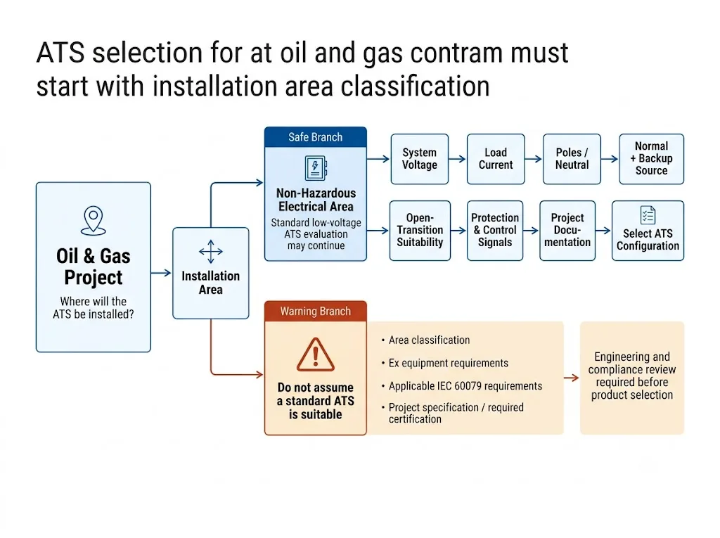
Compliance with IEC 60947-6-1 alone does not make an ATS suitable for an explosive atmosphere. IEC 60079-14:2024 addresses electrical installation design, equipment selection, installation and initial inspection for equipment used in or associated with explosive atmospheres.[3]
Where May a Standard ATS Be Considered?
Depending on the approved design, a standard compact ATS may be evaluated in suitable non-hazardous areas such as:
- low-voltage control cabinets;
- auxiliary distribution boards;
- control-room auxiliary power;
- monitoring and communication supporting loads;
- generator-backed auxiliary circuits; and
- equipment skids where the project permits standard low-voltage equipment.
These are possible applications, not blanket approvals. Final suitability depends on the actual electrical design, installation area, environment and project specification.
How the ATS Fits Between Utility, Generator and the Control Panel
Transfer switching equipment transfers a connected load between available power sources.[1] In a typical backup arrangement, the ATS sits between the normal and standby source and the downstream auxiliary load.
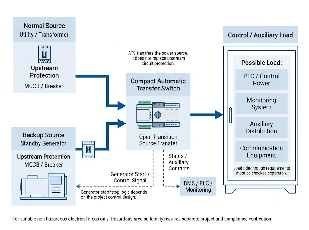
| Componente | Función Principal |
|---|---|
| ATS | Transfers the load between the selected power sources. |
| MCCB / breaker | Provides the required circuit protection according to the electrical design.[5] |
| Controlador ATS | Monitors source conditions and executes the configured transfer logic. |
| Generator controller | Controls generator starting, stopping and operation. |
| Auxiliary contacts | Provide status or position signals where supported by the selected ATS. |
Where the LEEYEE Compact ATS Fits
The LEEYEE product shown below is a compact integrated automatic transfer switch rather than a large engineered ATS cabinet. The pictured product family includes compact 2-pole and 4-pole configurations with front-panel Auto / Manual operation and source / load status indication.
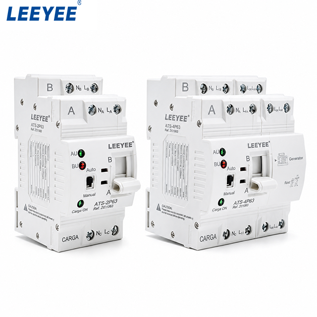
This product format is suitable for evaluating conventional low-voltage dual-source transfer in appropriately designed non-hazardous control or auxiliary distribution panels. It should not be confused with an explosion-proof ATS, bypass-isolation ATS or large oil-and-gas switchboard.
The standard LEEYEE compact ATS application direction is open-transition transfer. One source is disconnected before the second source supplies the load. If the downstream load cannot tolerate the intended interruption, the complete power-continuity architecture must be reviewed instead of assuming that the ATS alone can provide no-break power.
Significado técnico: the real product shown here supports the page because it demonstrates the actual ATS form factor LEEYEE supplies. It does not imply that this standard compact unit is approved for hazardous-area installation.
Use This Selection Sequence for a Non-Hazardous Control Panel
Determine whether the ATS will be installed in a confirmed non-hazardous electrical area.
Identify the normal and standby source and confirm system voltage and frequency.
Use the approved load and distribution design rather than selecting only from an assumed breaker rating.
For three-phase projects, confirm whether the neutral must remain connected or transfer with the phases.
Check whether the connected load can tolerate the designed interruption during transfer.
Check the actual ATS short-circuit data together with upstream protection and available fault current.
Confirm generator-start requirements, auxiliary contacts and any monitoring interface.
Review ambient temperature, enclosure, moisture, dust, corrosion and other project conditions.
Do Not Ignore the Panel Environment
A non-hazardous location does not automatically mean an easy environment. The ATS and the surrounding control panel must be evaluated against the actual site conditions.
Confirmar antes de la aprobación
Normal Source and Standby Generator
A generator-backed ATS arrangement requires coordination between the ATS controller and generator controller. The exact generator-start contact, terminals and sequence must be confirmed from the selected equipment documentation.
Some ATS controllers provide a generator-start relay output; Eaton documents one such implementation in its ATC-300+ controller.[6] This is an industry example, not a statement that every ATS uses the same interface.
- normal and backup source identity;
- source voltage and frequency;
- generator-start interface;
- source sensing requirements;
- transfer and retransfer logic;
- status and alarm signals; and
- controller responsibility.
ATS and MCCB Are Not the Same Device
IEC 60947-6-1 addresses transfer switching equipment, while IEC 60947-2 addresses circuit-breakers.[1][5] The ATS transfers the source; it should not be treated as a substitute for the upstream protective device.
A particular ATS current rating does not automatically establish suitability for every prospective short-circuit condition. Verify the exact ATS data, protective-device arrangement and project fault level before approval.
Should the Project Use a 3-Pole or 4-Pole ATS?
The answer does not come from the words “oil and gas.” It depends on the neutral arrangement, earthing system, generator neutral configuration, protection philosophy and approved electrical design.
The actual LEEYEE product image above shows both 2P and 4P compact configurations, but the correct pole count must still be selected from the electrical system requirements rather than appearance alone.
Hazardous Areas Require a Separate Compliance Decision
IEC 60947-6-1:2026 states that transfer switches used in explosive atmospheres are outside its scope and refers users to the IEC 60079 series.[1]
IEC 60079-10-1 addresses area classification, while IEC 60079-14 addresses design, equipment selection and installation for electrical installations associated with explosive atmospheres.[2][3]
Therefore, the standard compact LEEYEE ATS shown on this page should no be described as explosion-proof, IECEx-certified or hazardous-area suitable unless the specific product, certification scope and installation have been independently verified for that requirement.
| Decision Item | Non-Hazardous Area | Hazardous / Potentially Hazardous Area |
|---|---|---|
| First step | Continue normal ATS selection. | Confirm area classification first. |
| IEC 60947-6-1 | Relevant to transfer switching equipment within its scope. | Does not establish explosive-atmosphere suitability. |
| LEEYEE compact ATS | May be evaluated against electrical and project requirements. | Do not claim suitability without separate compliance verification. |
Before Requesting an ATS for an Oil & Gas Control Panel
Lista de Verificación de Información del Proyecto
- installation location;
- hazardous-area status;
- normal source;
- backup source;
- system voltage;
- frequency;
- single-phase or three-phase;
- rated load current;
- 2P, 3P or 4P requirement;
- sistema de neutro y puesta a tierra;
- load continuity requirement;
- generator-start requirement;
- auxiliary contacts;
- upstream protection;
- ambient and enclosure conditions;
- required standards or certificates;
- quantity;
- OEM documentation requirements.
Need to Confirm an ATS Configuration?
Send the installation area, voltage, current, pole requirement, normal and backup source information, generator-control requirement and project specification. LEEYEE can review the stated low-voltage transfer requirement and identify which points still require project confirmation.
PREGUNTAS FRECUENTES
Can this LEEYEE ATS be used in an oil and gas project?
It can be evaluated for suitable non-hazardous low-voltage control-panel or auxiliary power applications when its exact ratings, pole configuration, transfer function and environmental limits meet the project requirements. The industry name alone does not establish suitability.
Is this LEEYEE ATS explosion-proof?
This page does not claim that the standard compact ATS shown above is explosion-proof or certified for installation in a classified explosive atmosphere. Hazardous-area applications require separate equipment and compliance verification.
Can a normal ATS be installed in a hazardous area?
Do not assume so. IEC 60947-6-1:2026 excludes transfer switches used in explosive atmospheres from its scope and refers to the IEC 60079 series.[1]
Is open transition suitable for a PLC control panel?
It depends on the allowable interruption for the PLC and the rest of the control system. If the load cannot tolerate the interruption, review the complete continuity architecture.
Should I select 2P, 3P or 4P?
The pole configuration depends on phase arrangement, neutral treatment, earthing design and the project system. Do not select the pole count from the product appearance alone.
Referencias
- Comisión Electrotécnica Internacional (IEC), IEC 60947-6-1:2026 — Aparamenta de baja tensión — Parte 6-1: Equipos multifuncionales — Equipos de conmutación de transferencia. Página de publicaciones oficiales de la IEC.
- Comisión Electrotécnica Internacional (IEC), IEC 60079-10-1:2020 — Explosive atmospheres — Part 10-1: Classification of areas — Explosive gas atmospheres. Página de publicaciones oficiales de la IEC.
- Comisión Electrotécnica Internacional (IEC), IEC 60079-14:2024 — Explosive atmospheres — Part 14: Electrical installation design, selection and installation of equipment, including initial inspection. Página de publicaciones oficiales de la IEC.
- Comisión Electrotécnica Internacional (IEC), IEC 60947-2:2024 — Aparamenta de baja tensión — Parte 2: Disyuntores. Página de publicaciones oficiales de la IEC.
- Eaton, ATC-300+ Automatic Transfer Switch Controller — Operation and Maintenance Manual. Manual oficial de Eaton.
