
El cableado de SPD TN-C-S depende primero del punto de separación del PEN, no solo de si un producto se describe como 3P, 4P o 3P+N.
Esta guía ayuda a los constructores de paneles, contratistas eléctricos, consultores, distribuidores y compradores de OEM a determinar si el SPD se instalará en la sección TN-C o en la sección TN-S separada.
Índice
Respuesta rápida: ¿Dónde debe conectarse el SPD?
Un suministro TN-C-S contiene dos secciones eléctricamente diferentes:
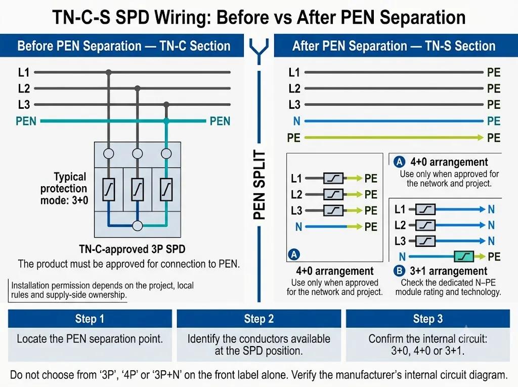
- Antes de la separación del PEN: las funciones neutra y de tierra de protección comparten el conductor PEN. Esta es la sección TN-C.
- Después de la separación del PEN: N y PE son separados. Esta sección descendente se considera como TN-S.
| Ubicación de SPD | Conductores presentes | Dirección de selección |
|---|---|---|
| Antes de la separación | L1, L2, L3, PEN | Utilice un arreglo de 3P o 3+0 aprobado por TN-C conectado desde las fases a PEN. |
| En la separación | PEN se divide en N y PE separados | Confirme la conexión exacta, el límite de propiedad y las normas nacionales en los documentos del proyecto. |
| Después de la separación | L1, L2, L3, N, PE | Utilice un SPD aprobado para la sección TN-S. Dependiendo del diseño, esto puede usar modos de protección 4+0 o 3+1. |
| Panel aguas abajo | Separar N y PE | Trate el punto de protección como TN-S y coordínelo con el SPD aguas arriba. |
El número de polos por sí solo no confirma el circuito de protección interno.
¿Cómo cambia el sistema TN-C-S en la separación del PEN?
PEN es un conductor que realiza funciones tanto de protección a tierra como de neutro. Antes de la separación, una sección TN-C de tres fases normalmente tiene L1, L2, L3 y PEN.
En el punto de separación designado, PEN se divide en:
- N: el conductor neutro utilizado para el retorno de corriente de carga normal.
- PE: el conductor de protección utilizado para la puesta a tierra y los caminos de corriente de falla.
Después de la separación, N y PE tienen funciones diferentes y deben permanecer separadas a lo largo de la instalación posterior. La IEC 60364-1 proporciona el marco y la terminología fundamental para las disposiciones de puesta a tierra en baja tensión.[1]
Schneider Electric también distingue la parte TN-C antes de la separación de la parte TN-S después de la separación al explicar la idoneidad del SPD en una red TN-C-S.[2]

Una descripción del proyecto que solo dice “TN-C-S” es incompleta para la selección del SPD. El diagrama unifilar debe mostrar dónde PEN se convierte en N y PE y dónde se instalará el SPD.
¿Debería instalarse el SPD antes o después de la separación del PEN?
No hay una posición de instalación única que se aplique a todos los proyectos TN-C-S.
En muchos cuadros eléctricos del lado del cliente, el SPD se instala después de la separación de PEN. El punto de protección está entonces en la parte TN-S del suministro.
También puede aplicarse un SPD en la sección TN-C cuando el diseño del proyecto, el límite de suministro y las normas locales lo permitan. En ese caso, el producto debe estar homologado para la conexión entre los conductores de fase y PEN.
Schneider Electric indica que un SPD compatible con TN-S puede utilizarse en la parte TN-S de una red TN-C-S, mientras que en la parte TN-C se requiere un SPD 3P compatible con TN-C.[2]
Antes de la separación de PEN: sección TN-C
Los conductores disponibles suelen ser L1, L2, L3 y PEN. En este punto no existe un conductor N independiente ni un conductor PE independiente.
Una configuración de protección 3+0 típica conecta:
- L1 a PEN
- L2 a PEN
- L3 a PEN
DEHN publica una instalación de ejemplo TN-C utilizando una configuración 3+0.[3]
Antes de aprobar el modelo, confirme que es explícitamente apto para uso TN-C, que su diagrama permite la conexión a PEN y que la ubicación de la instalación está permitida por la autoridad de proyecto o de suministro responsable.
Después de la separación del PEN: sección TN-S
Los conductores disponibles son L1, L2, L3, N y PE. El SPD ahora se instala en la parte TN-S separada del sistema TN-C-S.
Los documentos de aplicación del fabricante muestran que las soluciones TN-S aprobadas pueden utilizar diferentes disposiciones internas. DEHN publica una instalación de ejemplo TN-S utilizando 4+0 y también enumera productos 3+1 para sistemas TT y TN-S.[3]
La elección final entre 4+0 y 3+1 depende del diseño aprobado del producto, de las normas nacionales, de los requisitos TOV, de la coordinación con RCD y de la especificación del proyecto.
Una disposición especial cerca de la separación no es una regla universal
Un libro blanco de DEHN sobre aparamenta muestra una disposición específica en la que otro SPD 3+0 puede instalarse a una distancia máxima de 0,5 m del punto de separación del PEN.[4]
Este es un ejemplo de aplicación del fabricante con condiciones definidas. No utilice solo la distancia para aprobar una regla general de cableado TN-C-S. Confirme la norma nacional, el límite de propiedad, la documentación del producto y el plano del proyecto.
¿3P, 4P o 3P+N: qué debe verificar el comprador?
El número de módulos visibles no siempre explica cómo está conectado internamente el SPD.
La terminología del proveedor puede variar. El diagrama de circuito interno es el documento de referencia.
| Descripción | Posible significado | Se requiere verificación |
|---|---|---|
| SPD de 3P | Tres polos de protección, a menudo utilizados para 3+0. | Si los recorridos son L-PEN o L-PE y qué tipo de red está aprobado. |
| SPD 4P | Cuatro polos de protección, a menudo utilizados para 4+0. | Cómo se conectan L1, L2, L3, N y PE dentro del producto. |
| 3P+N | Se utiliza con frecuencia en aplicaciones comerciales para un producto 3+1. | Si contiene tres vías L-N y un elemento de protección N-PE dedicado. |
| 3+0 | Tres modos de protección de conductor activo a referencia. | Si la referencia es PEN o PE y si la aplicación en red está aprobada. |
| 4+0 | Cuatro modos de protección de conductor activo a PE. | Comportamiento de Uc, Up y TOV, características de fuga y aprobación para aplicación TN-S. |
| 3+1 | Tres modos de protección L-N más un modo N-PE. | La tecnología N-PE, la capacidad de descarga, Uc y el nivel de protección combinado L-PE. |
Solicite el diagrama del circuito interno, la hoja de datos y las instrucciones de instalación antes de aprobar el modelo.
¿Cómo deben manejarse N y PE después de la separación?
Después del punto de separación aprobado, N transporta la corriente normal de retorno de carga. PE proporciona la unión equipotencial de protección y las vías para la corriente de falla.
Un elemento de protección N-PE diseñado dentro de un SPD no es lo mismo que un puente permanente de cobre entre las barras de neutro y PE.
Comprobaciones correctas
- Mantenga separadas las barras N y PE aguas abajo.
- Siga el esquema de cableado del SPD seleccionado.
- Utilice una conexión PE corta y directa.
- Ponga a tierra la envolvente según el diseño aprobado.
- Verifique el aislamiento del neutro cuando sea necesario.
Errores comunes
- Añadir un enlace permanente N-PE en el SPD.
- Utilizar un borne del SPD como barra de neutro.
- Seguir etiquetando el PE aguas abajo como PEN.
- Reconectar N y PE en un cuadro de subdistribución.
- Suponer que cada módulo neutro es un elemento N-PE.
Una conexión N-PE no intencionada puede alterar las trayectorias de corriente y afectar el funcionamiento del dispositivo de protección. La disposición final de unión equipotencial debe coincidir con el diseño de puesta a tierra aprobado.
Detalles de instalación que afectan el rendimiento real del SPD
Mantenga corta la ruta de conexión
Los conductores largos añaden tensión inductiva durante una sobretensión. Por tanto, la tensión que llega al equipo puede ser mayor de lo que sugiere por sí solo el valor Up indicado del SPD.
Las directrices oficiales de instalación de Weidmüller establecen que los conductores de conexión del SPD no deben superar 0.5 m y explican que la conexión en V puede reducir la tensión adicional del conductor.[6]
- Coloque el SPD cerca de los conductores de entrada y de la barra PE o PEN.
- Evite bucles, desvíos y curvas innecesarias.
- No coloque el SPD en el extremo más alejado del carril DIN solo porque haya espacio disponible.
- Confirme si la conexión en V o el cableado en derivación está aprobado para el modelo.
Coordinar la protección de respaldo y la capacidad frente a cortocircuitos
El dispositivo de protección contra sobrecorriente aguas arriba, los conductores de derivación del SPD y la capacidad del SPD frente a cortocircuitos deben evaluarse conjuntamente.
Weidmüller indica que se necesita protección de respaldo adicional cuando el dispositivo de protección del lado del sistema supera el valor máximo especificado para el SPD.[6] DEHN también señala que el Isccr requerido debe ser al menos igual a la corriente de cortocircuito en el punto de conexión.[4]
- Corriente de cortocircuito prospectiva en el punto de instalación.
- Isccr del SPD o capacidad de cortocircuito indicada.
- Fusible o disyuntor de respaldo máximo permitido.
- Tipo y clasificación del dispositivo de protección aguas arriba.
- Sección transversal y recorrido del conductor de derivación.
- Si la protección de respaldo está integrada.
Verifique todas las clasificaciones eléctricas
El circuito de protección correcto no significa automáticamente que las clasificaciones eléctricas sean correctas.
- Uc: tensión máxima de funcionamiento continuo.
- Arriba: nivel de protección de tensión.
- In, Imax o Iimp: según la clasificación y la aplicación del SPD.
- Comportamiento TOV: rendimiento durante sobretensión temporal a frecuencia de red.
- Clasificaciones N-PE: cuando se utiliza un modo de protección N-PE dedicado.
IEC 60364-5-53 incluye los requisitos de selección e instalación de los dispositivos de protección en instalaciones de baja tensión, incluidas las disposiciones sobre SPD en la Cláusula 534.[5] IEC 61643-11:2025 establece requisitos y métodos de ensayo para los SPD conectados a sistemas de corriente alterna de baja tensión.[8]
Confirme la coordinación del RCD
La posición y la inmunidad del RCD dependen de la red, el circuito del SPD, el comportamiento de fuga, el tipo de RCD, los requisitos de selectividad y las normas nacionales.
No aplique una única configuración universal de RCD a todos los proyectos TN-C-S. Revise el diagrama de protección completo y las instrucciones de ambos dispositivos.
¿Protege un SPD contra un PEN roto?
No. Un SPD estándar no es un dispositivo completo de protección contra conductor PEN abierto.
Un SPD limita las sobretensiones transitorias. Un PEN roto es una falla de la red de frecuencia de potencia que puede causar desplazamiento del neutro, corriente desviada y tensión de contacto peligrosa.
La IET explica que un PEN abierto puede poner tensión peligrosa en las partes metálicas unidas y puede producir sobretensión en algunas cargas y subtensión en otras.[7]
No confunda dos funciones de protección diferentes
- SPD: limita las sobretensiones transitorias relacionadas con rayos y maniobras de conmutación.
- Protección contra PEN abierto: detecta, desconecta o controla de otro modo una falla peligrosa de PEN de acuerdo con las reglas de diseño aplicables.
Siete errores comunes en SPD TN-C-S
- Seleccionar solo a partir de “TN-C-S”. El nombre del sistema no muestra qué lado de la separación del PEN contiene el SPD.
- Usar un SPD solo para TN-S en la sección TN-C. Un producto diseñado para N y PE separados no debe conectarse automáticamente a PEN.
- Suponer que todo proyecto TN-C-S requiere 3+1. Las soluciones TN-S aprobadas pueden usar 4+0 o 3+1, según el diseño.
- Suponer que todo SPD de cuatro módulos es 3+1. El circuito interno puede ser, en cambio, 4+0.
- Añadir un puente N-PE aguas abajo. Esto cambia la disposición de puesta a tierra prevista.
- Ignorar la longitud de conexión y la protección de respaldo. Ambos pueden modificar la protección efectiva y la aprobación del panel.
- Tratar el SPD como protección contra PEN abierto. Estos dispositivos abordan distintos riesgos eléctricos.
Flujo de trabajo de selección de ingeniería de SPD TN-C-S
El proceso de decisión debe comenzar con el esquema eléctrico, no con el número de módulos del proveedor.
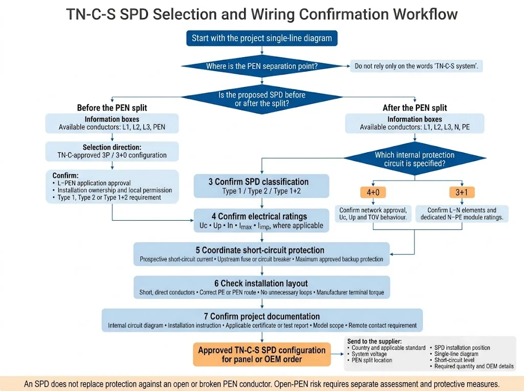
- Localice el punto de separación del PEN. Márcelo claramente en el diagrama unifilar.
- Identifique la posición propuesta del SPD. Confirme si está en la sección TN-C o en la sección TN-S separada.
- Apruebe el circuito interno. Verifique 3+0, 4+0 o 3+1 en la documentación del producto.
- Confirme la clasificación y los valores nominales del SPD. Compruebe Type, Uc, Up, In, Imax, Iimp cuando corresponda y el comportamiento frente a TOV.
- Coordine la instalación. Compruebe Isccr, la protección de respaldo, el tendido de los conductores, la longitud de conexión y los requisitos de los terminales.
- Registre el modelo aprobado. Conserve la ficha técnica, el esquema de cableado, el alcance del certificado y la referencia de sustitución en la documentación del panel.
¿Qué debe confirmarse antes de realizar un pedido?
Lista de verificación de consulta de panel y OEM
- País y norma de instalación aplicable.
- Tensión nominal del sistema.
- Alimentación monofásica o trifásica.
- Configuración del conductor de entrada.
- Punto exacto de separación PEN.
- Posición propuesta de instalación del SPD.
- Diagrama unifilar marcado.
- Tipo de SPD requerido.
- Circuito 3+0, 4+0 o 3+1 requerido.
- Requisitos de Uc, Up y corriente de descarga.
- Corriente de cortocircuito prospectiva.
- Clasificación del dispositivo de protección aguas arriba.
- Requisito de señalización remota.
- Requisito de certificado o informe de ensayo.
- Requisitos de cantidad, etiqueta y embalaje.
Un diagrama unifilar marcado es más útil que la frase “necesitamos un SPD de cuatro polos para TN-C-S.”
¿Necesita confirmar una configuración de SPD TN-C-S?
Envíe la tensión del sistema, el punto de separación del PEN, la ubicación propuesta del SPD, el nivel de cortocircuito y el diagrama unifilar. LEEYEE puede revisar el circuito de protección requerido y preparar una lista de confirmación de modelo para proyectos de paneles, distribución u OEM.
Comparta los detalles de su sistema para revisiónLEEYEE es un proveedor especializado en protección contra sobretensiones y protección de baja tensión. CNSPD es la plataforma de LEEYEE centrada en la protección contra sobretensiones para compradores técnicos globales. Diseñado para proteger. Confiable a largo plazo.
Preguntas frecuentes
¿Se puede usar un SPD de 3P en un sistema TN-C-S?
Sí, cuando se instala en la sección TN-C y está aprobado explícitamente para la conexión desde L1, L2 y L3 a PEN.
¿Debe instalarse siempre el SPD después de la separación del PEN?
No. Los SPD del lado del cliente suelen instalarse después de la separación, pero se puede utilizar un SPD TN-C aprobado antes de la división cuando el proyecto y las normativas locales lo permitan.
¿Todos los sistemas TN-C-S requieren un SPD 3+1?
No. Tras la separación, las soluciones TN-S aprobadas pueden utilizar configuraciones 4+0 o 3+1, dependiendo del producto, el proyecto y la normativa aplicable.
¿Es un SPD de 4P lo mismo que un SPD de 3P+N?
No necesariamente. Un SPD de 4 polos puede utilizar un circuito 4+0, mientras que un producto 3P+N puede emplear tres vías L-N además de un elemento N-PE dedicado.
¿Se pueden conectar N y PE en el SPD?
No añada un nuevo puente N-PE permanente después del punto de separación PEN aprobado. Utilice los modos de protección diseñados dentro de un SPD aprobado.
¿Cuál es el documento más útil para la selección de modelos?
Un diagrama unifilar marcado que muestre la división PEN, la posición del SPD, la disposición de los conductores y la protección aguas arriba.
Guías técnicas relacionadas
Referencias
- Comisión Electrotécnica Internacional, IEC 60364-1:2025 — Instalaciones eléctricas de baja tensión — Parte 1: Principios fundamentales, evaluación de características generales y definiciones. Página de publicación oficial de la IEC.
- Schneider Electric Reino Unido, ¿Sería posible instalar un SPD TNS en una red TN-C-S?, FAQ000270719. El documento distingue las partes TN-C y TN-S de una red TN-C-S. Preguntas frecuentes oficiales de Schneider Electric.
- DEHN, Mayor seguridad para armarios de aparamenta. La información publicada sobre la aplicación incluye una muestra TN-C 3+0, una muestra TN-S 4+0 y productos 3+1 identificados para sistemas TT y TN-S. Documento técnico oficial de DEHN.
- DEHN, Protección contra sobretensiones en conjuntos de aparamenta de baja tensión, WPX004/E. El libro blanco analiza la caída de tensión del conductor, la Isccr y una aplicación 3+0 definida cerca de un punto de separación PEN. Libro blanco oficial de DEHN.
- Comisión Electrotécnica Internacional, IEC 60364-5-53:2019+AMD1:2020+AMD2:2024 CSV — Instalaciones eléctricas de baja tensión — Parte 5-53: Selección e instalación de equipos eléctricos. Página oficial de la versión consolidada de la IEC.
- Weidmüller, Información y requisitos de instalación: protección contra rayos y sobretensiones en sistemas energéticos. La guía abarca la instalación por personal cualificado, la ubicación del SPD, la longitud de las líneas de conexión, la conexión en V y la protección de respaldo. Guía oficial de Weidmüller.
- The Institution of Engineering and Technology, PEN interrumpido, Cuestiones de cableado. El artículo explica la corriente neutra desviada, la tensión de contacto peligrosa y el desplazamiento de tensión asociados a un PEN abierto. Artículo oficial de la IET.
- Comisión Electrotécnica Internacional, IEC 61643-11:2025 — Dispositivos de protección contra sobretensiones de baja tensión — Parte 11: Dispositivos de protección contra sobretensiones conectados a sistemas de alimentación de baja tensión de CA — Requisitos y métodos de ensayo. Página de publicación oficial de la IEC.
