
La longueur du câble SPD affecte directement la protection fournie à l'intérieur d'un tableau de distribution complet. Un dispositif de protection contre les surtensions peut avoir une tension Up déclarée basse, mais de longs fils de connexion peuvent ajouter une tension inductive et exposer l'équipement en aval à une tension plus élevée que ne le suggère uniquement la fiche technique du SPD.
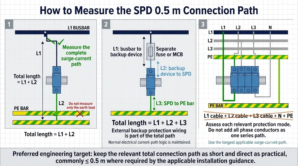
Gardez le chemin de connexion SPD complet aussi court et direct que possible. La règle couramment référencée de 0,5 m s'applique à l'ensemble du câblage pertinent entre les points de connexion de l'assemblage SPD, pas automatiquement pour chaque conducteur individuel.
Lorsqu'un fusible de secours ou un disjoncteur séparé est installé, le total peut inclure le conducteur de la barre omnibus au dispositif de secours, le conducteur du dispositif de secours à l'SPD, et le conducteur de l'SPD à PE, PEN ou neutre.
Dans les installations basées sur la norme BS 7671, le total ne doit de préférence pas dépasser 0,5 m et ne doit pas dépasser 1,0 m. D'autres marchés doivent suivre les règles nationales applicables et les instructions du fabricant de l'SPD.
Table des matières
Pourquoi les câbles de connexion SPD doivent-ils être courts ?
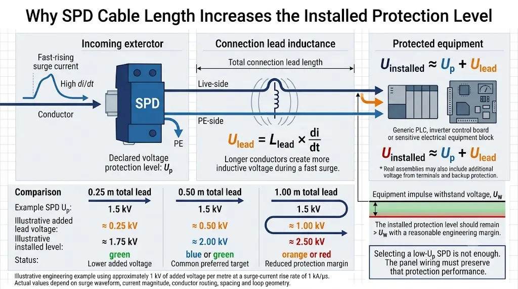
Le courant de surtension augmente beaucoup plus rapidement que le courant de fonctionnement normal de 50 Hz ou 60 Hz. À ce taux élevé de changement, l'inductance des conducteurs de connexion génère une tension supplémentaire.
Une approximation d'ingénierie couramment utilisée est d'environ 1 μH d'inductance par mètre de conducteur. Dans un exemple de courant de surtension 8/20 μs, cela peut correspondre à environ 1 kV de tension ajoutée par mètre de câble de connexion.
La tension ajoutée réelle dépend de l'amplitude de la surtension, de la forme d'onde, du chemin du conducteur, de l'espacement des conducteurs, de la surface de boucle, des bornes et de l'assemblage complet de la SPD. Il n'est pas correct d'affirmer que chaque mètre ajoute toujours exactement 1 kV.
Chemin plus long
Un chemin de connexion plus long a généralement plus d'inductance et produit donc une tension ajoutée plus importante lors d'une surtension rapide.
Surface de boucle plus grande
Les conducteurs éloignés ou autour de grandes boucles de coffrets peuvent encore augmenter l'effet d'installation.
Un câble plus épais ne suffit pas
Une section correcte est nécessaire, mais un câble plus épais n'élimine pas l'effet inductif d'un parcours inutilement long.
Comment la longueur de connexion SPD de 0,5 m est-elle mesurée ?
Les sections exactes des conducteurs dépendent de l'agencement de la connexion SPD. Dans le diagramme ci-dessous, L1, L2 et L3 identifient les sections de conduite..Elles ne représentent pas les trois phases électriques.
Sans appareil de sauvegarde SPD séparé
Lorsque le fabricant du SPD permet à l'appareil de protection en amont de fournir la protection de sauvegarde requise, il se peut qu'il n'y ait pas de section L1 séparée. Le total pertinent peut donc être :
Barre omnibus ou point de branchement vers le SPD + SPD vers PE, PEN ou neutre.
Avec un fusible de secours ou un disjoncteur séparé
Lorsque un dispositif de protection de secours dédié est requis, toutes les sections de connexion applicables doivent être prises en compte :
Barre omnibus vers le dispositif de secours + dispositif de secours vers le SPD + SPD vers PE, PEN ou neutre.
Panneaux triphasés
Ne pas additionner les longueurs physiques de tous les conducteurs de phase comme s'ils étaient un seul câble continu. Évaluer le chemin de protection applicable pour chaque mode et utiliser le chemin pertinent le plus long.
Ne pas mesurer la distance en ligne droite entre les boîtiers de l'appareil. Suivre le parcours réel du câble à travers les bornes, la protection de secours et les chemins de câbles.
 Ouvrir l'image en taille réelle
Exemple de longueur de câble SPD travaillé
Un SPD de Type 2 est installé à côté d'un MCB de secours dédié. La barre PE est située sous le SPD.
Mesure du panneau complétée
Les mêmes composants pourraient ne pas atteindre la cible si le disjoncteur de secours était déplacé vers une autre section de rail DIN ou si le conducteur PE était acheminé à travers l'intégralité de l'armoire. C'est pourquoi la position du SPD devrait être décidée lors de la mise en page du panneau—et non après que les composants restants aient déjà été placés.
Comment la longueur du câble modifie-t-elle le niveau de protection installé ?
Haut de la page est le niveau de protection de tension déclaré pour le SPD sous des conditions de test définies. L'équipement en aval peut voir une tension plus élevée après que les effets de connexion aient été inclus.
| Longueur de connexion totale | Tension ajoutée illustrée | Exemple avec SPD Up = 1,5 kV | Interprétation du panneau |
|---|---|---|---|
| 0,25 m | Environ 0,25 kV | Environ 1,75 kV | Connexion courte avec un pénalité d'installation moindre. |
| 0,50 m | Environ 0,50 kV | Environ 2,00 kV | Objectif de longueur de connexion préférée courante. |
| 1,00 m | Environ 1,00 kV | Environ 2,50 kV | La marge de protection peut être considérablement réduite. |
Le tableau utilise une approximation illustrative d'environ 1 kV par mètre. Ce n'est pas un produit garanti ou un calcul de performance sur le terrain.
 Ouvrir l'image en taille réelle
Ne demandez pas seulement : “ Qu'est-ce que le SPD Up ? ” Demandez plutôt : “ Quel niveau de protection le SPD sélectionné et l'arrangement de connexion du panneau proposé fourniront-ils ensemble ? ”
Comment un SPD doit-il être positionné à l'intérieur d'un tableau de distribution ?
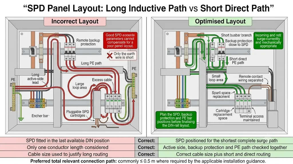
Le SPD, le dispositif de protection de secours et la connexion PE doivent être planifiés comme un seul ensemble fonctionnel. Installer le SPD dans la dernière position de rail DIN disponible crée souvent un chemin de connexion de mauvaise qualité.
Identifier le Point de Connexion Protégé
Confirmer où la branche SPD quittera le conducteur entrant, la barre omnibus ou la borne de distribution.
Positionner le Dispositif de Secours à Côté du SPD
Là où une protection de secours dédiée est nécessaire, un fusible à distance ou un disjoncteur peut consommer la majeure partie de la longueur de connexion autorisée.
Garder le Chemin PE Court et Direct
Placer le SPD près d'une connexion PE, PEN ou de mise à la terre appropriée plutôt que de faire passer le conducteur à travers le panneau.
Éviter les Boucles et les Itinéraires de Câble Inutiles
Ne pas stocker de câble excessif à côté du SPD. Coupez les conducteurs à la longueur requise et minimisez la zone entourée par le chemin de courant de surtension.
Réserver un Espace de Maintenance
Gardez l'indicateur, les terminaux, le contact à distance et la cartouche enfichable accessibles après avoir terminé le câblage.
 Ouvrir l'image en taille réelle
Que faire si la connexion SPD ne peut pas être maintenue dans les 0,5 m ?
N'essayez pas de résoudre un chemin de connexion excessif uniquement en augmentant la section transversale du câble. Examinez d'abord l'arrangement physique.
Repositionner le SPD
Déplacez le SPD plus près à la fois de la barre omnibus protégée et de la connexion PE, PEN ou neutre pertinente.
Déplacer la Protection de Secours
Placez le fusible ou le disjoncteur dédié directement à côté du SPD là où les instructions du produit le permettent.
Utilisez une connexion V-permise
Une connexion de type V ou à passage appropriée peut réduire l'effet de longs conducteurs de branche, mais seulement lorsque les bornes du SPD et les instructions du fabricant le permettent.
Utilisez un assemblage intégré
Un SPD avec protection de secours intégrée peut éliminer des sections de conducteurs externes et simplifier la conformité avec la cible de longueur de connexion.
Ne retirez pas la protection de secours requise, ne dépassez pas les évaluations de courant des bornes ou ne traitez pas un SPD parallèle normal comme un dispositif en série à pleine charge simplement pour raccourcir le câblage.
Liste de contrôle de confirmation pour les fabricants de panneaux et OEM
La longueur de connexion doit être considérée avant que le schéma du panneau et la liste des matériaux ne soient publiés.
Veuillez confirmer la largeur du module SPD, l'exigence de protection de secours, la capacité de conducteur de borne, l'agencement de connexion autorisé et le schéma d'installation. Notre objectif de panneau est un chemin de connexion SPD applicable complet dans les 0,5 m.
Questions fréquemment posées
Chaque conducteur SPD doit-il être plus court que 0,5 m ?
Non. La valeur couramment référencée de 0,5 m concerne normalement le chemin de connexion total applicable entre les points de connexion de l'assemblage SPD.
Seul le câble de terre de l'SPD est-il inclus dans la mesure ?
Non. Le conducteur du côté actif et le câblage à travers un dispositif de protection de secours séparé peuvent également faire partie du chemin total.
Un câble plus épais peut-il compenser une connexion SPD longue ?
Pas entièrement. La taille correcte du conducteur est nécessaire, mais l'augmentation de la section ne supprime pas l'effet inductif de la longueur excessive et de la zone de boucle.
Les longueurs des trois conducteurs de phase doivent-elles être ajoutées ensemble ?
Normalement non. Les trois conducteurs de phase sont généralement des chemins parallèles alternatifs, pas un chemin en série continu. Vérifiez chaque mode de protection applicable et utilisez le chemin le plus long pertinent.
Que se passe-t-il si le chemin de connexion total est de 1 m ?
La tension induite par la connexion peut augmenter considérablement le niveau de protection installé. Dans les installations basées sur la norme BS 7671, 1 m est indiqué comme la limite extérieure plutôt que comme l'objectif de conception préféré.
Quelle est la différence entre la règle des 0,5 m et celle des 10 m ?
La guidance de 0,5 m concerne le chemin de connexion propre de l'SPD. Le concept séparé de 10 m concerne la distance entre un SPD et un équipement distant ou un autre point de distribution, où une protection coordonnée supplémentaire peut devoir être évaluée.
Guides techniques SPD connexes
Références techniques
- IEC 60364-5-53:2019+AMD1:2020+AMD2:2024, installations électriques à basse tension et sélection et installation de matériel électrique. Page de publication officielle de l'IEC .
- IEC 61643-11:2025, dispositifs de protection contre les surtensions connectés aux systèmes électriques à basse tension AC—exigences et méthodes d'essai. Page de publication officielle de l'IEC .
- IET, BS 7671:2018 Séance de Questions-Réponses sur les Mythes, explication de la longueur de conducteur préférée de 0,5 m et maximale de 1,0 m. Voir le document IET .
- Guide d'installation électrique, connexion du dispositif de protection contre les surtensions, y compris la longueur totale de connexion, l'inductance de ligne et le niveau de protection installé. Voir le guide technique .
- Mersen, Solutions de Protection contre les Surtensions, conseils sur l'effet de longueurs de fils SPD plus longues sur les performances de clampage. Voir les conseils de Mersen .
Besoin de confirmer la disposition d'un SPD pour votre panneau ?
Envoyer le dessin du panneau, la tension du système, l'arrangement de mise à la terre, la position de l'SPD, l'arrangement de protection de secours et la position de la barre PE. LEEYEE peut aider à confirmer la configuration du produit et les informations nécessaires pour un devis OEM ou de projet.
Cet article fournit des conseils d'ingénierie et d'approvisionnement généraux. La sélection finale de l'SPD, le câblage, le dimensionnement des conducteurs, la protection de secours et la vérification doivent suivre la conception du projet, les réglementations nationales applicables, les exigences d'assemblage du panneau et les instructions spécifiques du fabricant de l'SPD.
