
TN-C-S SPD wiring depends first on the PEN separation point—not only on whether a product is described as 3P, 4P or 3P+N.
This guide helps panel builders, electrical contractors, consultants, distributors and OEM buyers determine whether the SPD will be installed on the TN-C section or on the separated TN-S section.
Table des matières
Quick Answer: Where Should the SPD Connect?
A TN-C-S supply contains two electrically different sections:
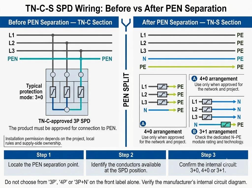
- Before PEN separation: neutral and protective-earth functions share the PEN conductor. This is the TN-C section.
- After PEN separation: N and PE are separate. This downstream section is treated as TN-S.
| SPD location | Conductors present | Selection direction |
|---|---|---|
| Before the split | L1, L2, L3, PEN | Use a TN-C-approved 3P or 3+0 arrangement connected from the phases to PEN. |
| At the split | PEN transitions to separate N and PE | Confirm the exact connection, ownership boundary and national rules from the project documents. |
| After the split | L1, L2, L3, N, PE | Use an SPD approved for the TN-S section. Depending on the design, this may use 4+0 or 3+1 protection modes. |
| Downstream panel | Separate N and PE | Treat the protection point as TN-S and coordinate it with the upstream SPD. |
The pole count alone does not confirm the internal protection circuit.
How Does the TN-C-S System Change at the PEN Split?
PEN is a conductor that performs both protective-earth and neutral functions. Before separation, a three-phase TN-C section normally has L1, L2, L3 and PEN.
At the designated separation point, PEN divides into:
- N: the neutral conductor used for normal load return current.
- PE: the protective conductor used for bonding and fault-current paths.
After separation, N and PE have different functions and should remain separate throughout the downstream installation. IEC 60364-1 provides the fundamental framework and terminology for low-voltage earthing arrangements.[1]
Schneider Electric also distinguishes the TN-C part before separation from the TN-S part after separation when explaining SPD suitability in a TN-C-S network.[2]

A project description that only says “TN-C-S” is incomplete for SPD selection. The single-line diagram must show where PEN becomes N and PE and where the SPD will be installed.
Should the SPD Be Installed Before or After PEN Separation?
There is no single installation position that applies to every TN-C-S project.
In many customer-side switchboards, the SPD is installed after PEN separation. The protection point is then on the TN-S part of the supply.
An SPD can also be applied on the TN-C section where the project design, supply boundary and local rules permit it. The product must then be approved for connection between the phase conductors and PEN.
Schneider Electric states that an SPD compatible with TN-S can be used on the TN-S part of a TN-C-S network, while a TN-C-compatible 3P SPD is required on the TN-C part.[2]
Before PEN separation: TN-C section
The available conductors are normally L1, L2, L3 and PEN. There is no separate N conductor or separate PE conductor at this point.
A typical 3+0 protection arrangement connects:
- L1 to PEN
- L2 to PEN
- L3 to PEN
DEHN publishes a TN-C sample installation using a 3+0 configuration.[3]
Before approving the model, confirm that it is explicitly suitable for TN-C use, that its diagram permits connection to PEN and that the installation location is allowed by the responsible project or supply authority.
After PEN separation: TN-S section
The available conductors are L1, L2, L3, N and PE. The SPD is now installed on the separated TN-S part of the TN-C-S system.
Manufacturer application documents show that approved TN-S solutions can use different internal arrangements. DEHN publishes a TN-S sample installation using 4+0 and also lists 3+1 products for TT and TN-S systems.[3]
The final choice between 4+0 and 3+1 depends on the approved product design, national rules, TOV requirements, RCD coordination and project specification.
A special arrangement near the split is not a universal rule
A DEHN switchgear white paper shows one specific arrangement in which another 3+0 SPD can be installed within a maximum distance of 0.5 m from the PEN separation point.[4]
This is a manufacturer application example with defined conditions. Do not use the distance alone to approve a global TN-C-S wiring rule. Confirm the national standard, ownership boundary, product documentation and project drawing.
3P, 4P or 3P+N: What Must the Buyer Verify?
The number of visible modules does not always explain how the SPD is connected internally.
Supplier terminology can vary. The internal circuit diagram is the controlling document.
| Description | Possible meaning | Verification required |
|---|---|---|
| SPD 3P | Three protective poles, often used for 3+0. | Whether the paths are L-PEN or L-PE and which network type is approved. |
| 4P SPD | Four protective poles, often used for 4+0. | How L1, L2, L3, N and PE connect inside the product. |
| 3P+N | Often used commercially for a 3+1 product. | Whether it contains three L-N paths and a dedicated N-PE protection element. |
| 3+0 | Three active-conductor-to-reference protection modes. | Whether the reference is PEN or PE and whether the network application is approved. |
| 4+0 | Four active-conductor-to-PE protection modes. | Uc, Up, TOV behaviour, leakage characteristics and TN-S application approval. |
| 3+1 | Three L-N protection modes plus one N-PE mode. | The N-PE technology, discharge rating, Uc and combined L-PE protection level. |
Request the internal circuit diagram, datasheet and installation instruction before model approval.
How Should N and PE Be Handled After the Split?
After the approved separation point, N carries normal load return current. PE provides protective bonding and fault-current paths.
A designed N-PE protection element inside an SPD is not the same as a permanent copper bridge between the neutral and PE bars.
Correct checks
- Keep the downstream N and PE bars separate.
- Follow the selected SPD wiring diagram.
- Use a short, direct PE connection.
- Bond the enclosure according to the approved design.
- Check neutral isolation where required.
Common errors
- Adding a permanent N-PE link at the SPD.
- Using an SPD terminal as the neutral bar.
- Continuing to label downstream PE as PEN.
- Reconnecting N and PE in a sub-distribution board.
- Assuming every neutral module is an N-PE element.
An unintended N-PE connection can alter current paths and affect protective-device operation. The final bonding arrangement must match the approved earthing design.
Installation Details That Affect Real SPD Performance
Keep the connection path short
Long conductors add inductive voltage during a surge. The voltage reaching the equipment can therefore be higher than the SPD’s stated Up value alone suggests.
Weidmüller’s official installation guidance states that SPD connecting lines should be no longer than 0.5 m and explains that V-connection can reduce additional conductor voltage.[6]
- Place the SPD close to the incoming conductors and PE or PEN bar.
- Avoid loops, detours and unnecessary bends.
- Do not place the SPD at the far end of the DIN rail only because space is available.
- Confirm whether V-connection or branch wiring is approved for the model.
Coordinate backup protection and short-circuit capability
The upstream overcurrent protective device, SPD branch conductors and SPD short-circuit capability must be evaluated together.
Weidmüller states that additional backup protection is needed when the system-side protective device exceeds the maximum value specified for the SPD.[6] DEHN also notes that the required Isccr must be at least equal to the short-circuit current at the point of connection.[4]
- Prospective short-circuit current at the installation point.
- SPD Isccr or stated short-circuit capability.
- Maximum permitted backup fuse or circuit breaker.
- Upstream protective-device type and rating.
- Branch conductor cross-section and routing.
- Whether backup protection is integrated.
Check all electrical ratings
The correct protection circuit does not automatically mean the electrical ratings are correct.
- Uc: maximum continuous operating voltage.
- Up: voltage protection level.
- In, Imax or Iimp: according to the SPD classification and application.
- TOV behaviour: performance during temporary power-frequency overvoltage.
- N-PE ratings: where a dedicated N-PE protection mode is used.
IEC 60364-5-53 includes the selection and erection requirements for protective devices in low-voltage installations, including the SPD provisions in Clause 534.[5] IEC 61643-11:2025 provides requirements and test methods for SPDs connected to AC low-voltage systems.[8]
Confirm RCD coordination
RCD position and immunity depend on the network, SPD circuit, leakage behaviour, RCD type, selectivity requirements and national rules.
Do not apply one universal RCD arrangement to every TN-C-S project. Review the complete protection diagram and the instructions for both devices.
Does an SPD Protect Against a Broken PEN?
No. A standard SPD is not a complete open-PEN protection device.
An SPD limits transient overvoltages. A broken PEN is a power-frequency network fault that can cause neutral displacement, diverted current and dangerous touch voltage.
The IET explains that an open PEN can place hazardous voltage on bonded metalwork and can produce overvoltage on some loads and undervoltage on others.[7]
Do not confuse two different protection functions
- SPD: limits lightning-related and switching transient overvoltages.
- Open-PEN protection: detects, disconnects or otherwise controls a dangerous PEN fault according to the applicable design rules.
Seven Common TN-C-S SPD Mistakes
- Selecting from “TN-C-S” alone. The system name does not show which side of the PEN split contains the SPD.
- Using a TN-S-only SPD on the TN-C section. A product designed for separate N and PE should not automatically be connected to PEN.
- Assuming every TN-C-S project requires 3+1. Approved TN-S solutions may use 4+0 or 3+1 depending on the design.
- Assuming every four-module SPD is 3+1. The internal circuit may instead be 4+0.
- Adding a downstream N-PE bridge. This changes the intended earthing arrangement.
- Ignoring connection length and backup protection. Both can change the effective protection and panel approval.
- Treating the SPD as open-PEN protection. These devices address different electrical risks.
TN-C-S SPD Engineering Selection Workflow
The decision process should begin with the electrical drawing—not with the supplier’s module count.
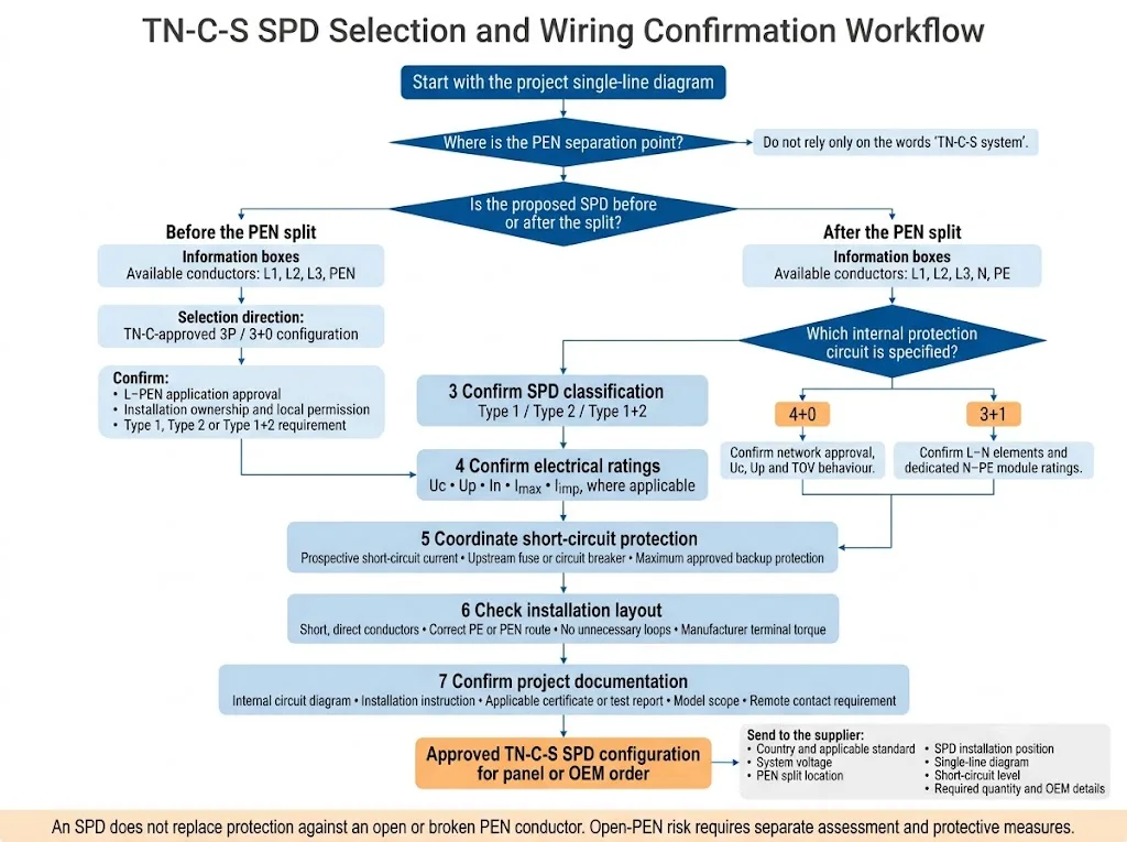
- Locate the PEN separation point. Mark it clearly on the single-line diagram.
- Identify the proposed SPD position. Confirm whether it is on the TN-C section or separated TN-S section.
- Approve the internal circuit. Verify 3+0, 4+0 or 3+1 from the product documentation.
- Confirm the SPD classification and ratings. Check Type, Uc, Up, In, Imax, Iimp where applicable and TOV behaviour.
- Coordinate the installation. Check Isccr, backup protection, conductor routing, connection length and terminal requirements.
- Record the approved model. Keep the datasheet, wiring diagram, certificate scope and replacement reference in the panel documentation.
Que doit-on confirmer avant de commander ?
Panel and OEM enquiry checklist
- Country and applicable installation standard.
- Nominal system voltage.
- Single-phase or three-phase supply.
- Incoming conductor arrangement.
- Exact PEN separation point.
- Proposed SPD installation position.
- Marked single-line diagram.
- Required SPD Type.
- Required 3+0, 4+0 or 3+1 circuit.
- Uc, Up and discharge-current requirements.
- Courant de court-circuit potentiel.
- Upstream protective-device rating.
- Remote signalling requirement.
- Certificate or test-report requirement.
- Quantity, label and packaging requirements.
A marked single-line diagram is more useful than the sentence “we need a four-pole SPD for TN-C-S.”
Need to Confirm a TN-C-S SPD Configuration?
Send the system voltage, PEN separation point, proposed SPD location, short-circuit level and single-line diagram. LEEYEE can review the required protection circuit and prepare a model-confirmation list for panel, distribution or OEM projects.
Share Your System Details for ReviewLEEYEE is a specialized surge protection and low-voltage protection supplier. CNSPD is LEEYEE’s surge protection-focused platform for global technical buyers. Built to Protect. Trusted to Last.
Questions fréquemment posées
Can a 3P SPD be used in a TN-C-S system?
Yes, when it is installed on the TN-C section and is explicitly approved for connection from L1, L2 and L3 to PEN.
Must the SPD always be installed after PEN separation?
No. Customer-side SPDs are often installed after separation, but an approved TN-C SPD may be used before the split where the project and local rules permit it.
Does every TN-C-S system require a 3+1 SPD?
No. After separation, approved TN-S solutions may use 4+0 or 3+1 depending on the product, project and applicable rules.
Is a 4P SPD the same as a 3P+N SPD?
Not necessarily. A 4P SPD may use a 4+0 circuit, while a 3P+N product may use three L-N paths plus a dedicated N-PE element.
Can N and PE be linked at the SPD?
Do not add a new permanent N-PE bridge after the approved PEN separation point. Use the designed protection modes inside an approved SPD.
What is the most useful document for model selection?
A marked single-line diagram showing the PEN split, SPD position, conductor arrangement and upstream protection.
Guides techniques connexes
Références
- International Electrotechnical Commission, IEC 60364-1:2025 — Low-voltage electrical installations — Part 1: Fundamental principles, assessment of general characteristics, and definitions. Page de publication officielle de l'IEC.
- Schneider Electric UK, Would it be possible to install a TNS SPD on a TN-C-S network?, FAQ000270719. The document distinguishes the TN-C and TN-S parts of a TN-C-S network. Official Schneider Electric FAQ.
- DEHN, Increased Safety for Switchgear Cabinets. The published application information includes a TN-C 3+0 sample, a TN-S 4+0 sample and 3+1 products identified for TT and TN-S systems. Official DEHN technical document.
- DEHN, Surge Protection in Low-Voltage Switchgear Assemblies, WPX004/E. The white paper discusses conductor voltage drop, Isccr and a defined 3+0 application near a PEN separation point. Official DEHN white paper.
- International Electrotechnical Commission, IEC 60364-5-53:2019+AMD1:2020+AMD2:2024 CSV — Low-voltage electrical installations — Part 5-53: Selection and erection of electrical equipment. Official IEC consolidated-version page.
- Weidmüller, Installation Information and Requirements — Lightning and Surge Protection in Energy Systems. The guidance covers qualified installation, SPD location, connecting-line length, V-connection and backup protection. Official Weidmüller guidance.
- The Institution of Engineering and Technology, Broken PEN, Wiring Matters. The article explains diverted neutral current, dangerous touch voltage and voltage displacement associated with an open PEN. Official IET article.
- International Electrotechnical Commission, IEC 61643-11:2025 — Low-voltage surge protective devices — Part 11: Surge protective devices connected to AC low-voltage power systems — Requirements and test methods. Page de publication officielle de l'IEC.
