
Sélection d'un data center automatic transfer switch starts with the power architecture, not with the ATS current rating. First identify the normal and emergency sources, the ATS position in the single-line diagram, the UPS position, and the interruption the downstream load can accept. Only then should the project team confirm poles, current rating, protection coordination and remote signals.
Table des matières
Quick Answer: Is an ATS Suitable for a Data Center?
Yes, but not every data-center circuit needs the same transfer equipment. A compact open-transition ATS can be evaluated for suitable generator-backed distribution, auxiliary power and other circuits where the downstream load can accept the transfer interruption or a correctly designed UPS provides the required ride-through. ABB's data-center technical material shows an architecture in which transfer switching is positioned upstream of a UPS.[2]
A standard compact open-transition ATS should not automatically be specified for every mission-critical load. IEC 60947-6-1:2026 covers transfer switching equipment and specifically includes bypass/isolation transfer switch equipment and ATSE with closed-transition capability, while static transfer switches are covered by the IEC 62310 series.[1][3]
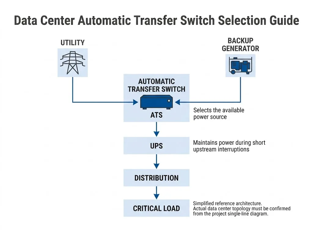
Where Does an Automatic Transfer Switch Fit in a Data Center?
An automatic transfer switch transfers a connected load between power supply sources. IEC 60947-6-1:2026 covers manually, remotely and automatically operated transfer switching equipment, including ATSE and its controller.[1]
A common standby arrangement uses utility power as the normal source and a generator as the alternate source. Other two-source arrangements are also possible. Eaton's ATS guidance describes source arrangements including utility-generator, utility-utility and generator-generator configurations.[4]
The first procurement question is therefore not simply “Which data center ATS should we buy?” It is “Which two sources are being transferred, where is the ATS in the single-line diagram, and which load does it actually supply?”
Mark the proposed ATS position on the single-line diagram before selecting a model. Identify both sources, the UPS position, upstream protective devices and downstream load. A switch can have the correct nominal current and still be unsuitable if the transfer method, pole arrangement or system role is wrong.
ATS vs UPS: They Solve Different Power Problems
An ATS and a UPS are not interchangeable. The ATS determines which available source supplies the connected circuit. The UPS performs a different continuity and power-conditioning role for its supported downstream load.
ABB's data-center transfer-switching material shows an architecture where transfer switching is upstream of a UPS. In this type of arrangement, the UPS is part of the strategy for keeping sensitive downstream equipment supplied while the upstream source changes.[2]
Interrupteur de transfert automatique
Monitors source availability and transfers the connected circuit between normal and alternate sources according to the equipment and project control logic.[4]
UPS
Supports its downstream load according to the selected UPS architecture and operating conditions. Its location therefore changes how an upstream source transfer affects sensitive equipment.[2]
Do not tell the ATS supplier only that “the project has a UPS.” Show whether the UPS is before or after the proposed ATS, identify the loads it supports, and confirm its required ride-through from the approved UPS design documentation.
First Decision: Can the Load Accept Open Transition?
LEEYEE's standard compact ATS product format is intended for open-transition automatic source transfer. In an open-transition sequence, the connected source is disconnected before the alternate source is connected. This is commonly described as break-before-make operation.
Closed transition is a different transfer capability. IEC 60947-6-1:2026 includes specific provisions for ATSE with closed-transition capability, so closed transition should not be assumed to be a standard function of an ordinary open-transition ATS.[1]
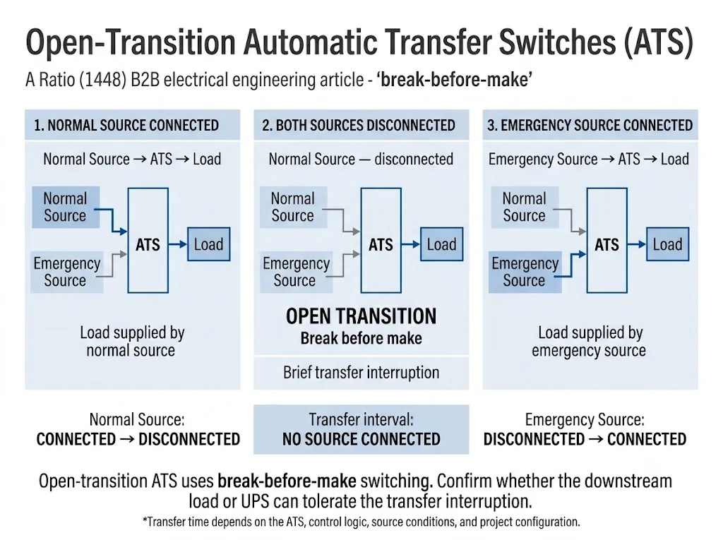
Open transition may be evaluated when:
- the actual downstream load can accept the transfer interruption;
- a correctly designed downstream UPS supports sensitive loads through the upstream transfer;
- the ATS serves a suitable generator-backed or auxiliary distribution circuit;
- the project specification permits open-transition operation; and
- the source, grounding and protection arrangements have been reviewed.
A load does not become suitable for a compact open-transition ATS merely because it is located inside a data center. If the circuit requires another transfer-continuity level or a specialized critical-power architecture, stop the standard ATS selection process and confirm the required solution with the project electrical designer.
When Should STS, Closed Transition or Bypass/Isolation Be Reviewed?
Different transfer technologies address different engineering requirements. IEC 60947-6-1:2026 specifically includes bypass/isolation transfer switch equipment and ATSE with closed-transition capability. Static transfer switches are excluded from that standard's scope because they are covered by the IEC 62310 series.[1][3]
ATS versus STS or open versus closed transition should therefore not be treated as a simple feature comparison. The correct direction depends on required continuity, source relationship, load characteristics, maintenance strategy and the complete electrical architecture.
| Condition du projet | Direction to evaluate | Confirmer avant de faire son choix |
|---|---|---|
| Brief transfer interruption is acceptable | Open-transition ATS may be evaluated | Load tolerance and transfer sequence |
| Downstream UPS supports sensitive load | Upstream ATS may be possible | UPS location and actual ride-through design |
| Closed transition is specified | ATSE à transition fermée | Source conditions and project requirements |
| Bypass/isolation is specified | Dedicated bypass/isolation arrangement | Maintenance and isolation requirements |
| Static transfer is specified | STS architecture | Load, source and IEC 62310 requirements |
Procurement conclusion: similar voltage and current ratings do not make open-transition ATS, closed-transition ATSE, bypass/isolation equipment and STS interchangeable.
Data Center ATS Selection: Follow This Decision Sequence
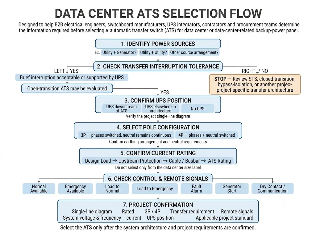
The practical selection path moves from the power architecture toward the device specification. This prevents a common procurement mistake: choosing the amperage first and discovering later that the transfer method, neutral arrangement or monitoring requirements do not match the project.
-
Identify the two power sources.
Confirm whether the circuit transfers between utility and generator, two utility sources, generators or another approved two-source arrangement.
-
Confirm the acceptable transfer interruption.
Determine whether open transition is acceptable for the actual downstream load and electrical architecture.
-
Locate the UPS in the single-line diagram.
Identify whether a UPS is downstream of the proposed ATS and exactly which loads it supports.
-
Determine whether the neutral must be switched.
Review source grounding and bonding before deciding between a three-pole and four-pole arrangement.
-
Confirm current and protection requirements.
Use the actual circuit design, upstream protection and available fault information instead of a generic data-center size category.
-
Define remote control and monitoring.
Confirm generator-start requirements, dry contacts, source/load status and BMS or PLC interfaces before production.
3P vs 4P ATS: Neutral Switching Is the Key Question
Do not use the shortcut “three-phase four-wire system = 4P ATS.” The engineering question is whether the neutral conductor should remain continuous or be switched together with the phase conductors.
Schneider Electric / ASCO technical guidance describes solid-neutral and switched-neutral transfer-switch configurations and explains that the appropriate arrangement is related to the grounding of the alternate source, including whether it is treated as a separately derived system.[5][6]
3P Arrangement
The phase conductors are transferred while the neutral remains continuous. Whether this arrangement is appropriate must be confirmed from the source grounding and bonding design.
4P Arrangement
The neutral is transferred together with the phase conductors. It may be required by particular source and grounding arrangements, but it should not be selected from phase count alone.
Provide the grounding or earthing arrangement, generator neutral configuration and single-line diagram before fixing the pole configuration. Multiple generators, multiple transfer switches, ground-fault protection and other complex systems require project-specific review.[5][6]
How Should the ATS Current Rating Be Selected?
Select the ATS for the circuit it actually serves. Do not derive the ATS rating from labels such as “small data center,” “medium data center” or from the facility's total IT capacity without confirming the load at the proposed ATS position.
Start with the design load current of the ATS feeder. Then verify the selected equipment against system voltage and frequency, load characteristics, upstream protection, conductor or busbar design, model-specific manufacturer ratings and the project's short-circuit coordination requirements.
Two facilities with similar total IT capacity can require different ATS ratings because the switches may serve different distribution blocks. For model review, provide the electrical data for the actual ATS feeder rather than only the overall data-center capacity.
| Paramètres | Pourquoi c'est important | Documents à fournir |
|---|---|---|
| System voltage / frequency | Electrical compatibility | Project design values |
| Design load current | Starting point for current selection | Current of the actual ATS feeder |
| Upstream protection | Protection coordination | Breaker or fuse information |
| Short-circuit information | Fault-condition suitability | Project fault data where available |
| Load characteristics | Can affect equipment selection | Relevant load type and operating conditions |
Final current and short-circuit suitability must be verified against the selected ATS documentation and the project's protection design. Do not infer a universal data-center ATS rating from this guide.
Generator Coordination Is Part of ATS Selection
In a utility-generator arrangement, the ATS is part of a control sequence rather than an isolated switch. Eaton describes a typical sequence in which the normal source fails, the alternate source becomes available, the load transfers, and the switch later returns the load after the normal source is restored.[4]
Generator-start logic, source-acceptance thresholds, transfer delays, retransfer delays and generator cool-down requirements are equipment- and project-specific. Use the approved ATS/controller documentation, generator design and project sequence of operation rather than copying generic settings.
A value that is suitable for one installation may be inappropriate for another. Data-center projects can use different generators, UPS systems and distribution architectures. Confirm the actual controller functions and approved settings during engineering review and commissioning.
What Remote Signals Should Be Confirmed?
Data-center and equipment-room projects may need ATS status outside the front panel. Define these requirements before ordering because available contacts, communication interfaces and control permissions depend on the selected ATS and controller.
Typical project points to confirm
- Normal Available
- Emergency Available
- Load to Normal
- Load to Emergency
- Fault Alarm
- Generator Start Signal
- Dry Contact Requirements
- BMS / PLC Interface
These are project confirmation items, not a statement that every LEEYEE ATS model includes every function. Before production, verify the selected model's terminal definitions, contact ratings, available communication hardware, protocol and point list from its technical documentation.
Where a Compact LEEYEE ATS May Fit
Keep the product scope clear
LEEYEE's standard ATS product format is a compact integrated automatic transfer switch intended for low-voltage source-transfer applications. For this page, the relevant selection path is ordinary open-transition transfer. Final suitability still depends on the specific circuit, load and project requirements.
The image below shows the actual compact product format discussed in this guide. The photographed units include LEEYEE 2-pole and 4-pole ATS versions with front Auto / Manual controls and clearly identified source and load connection areas.
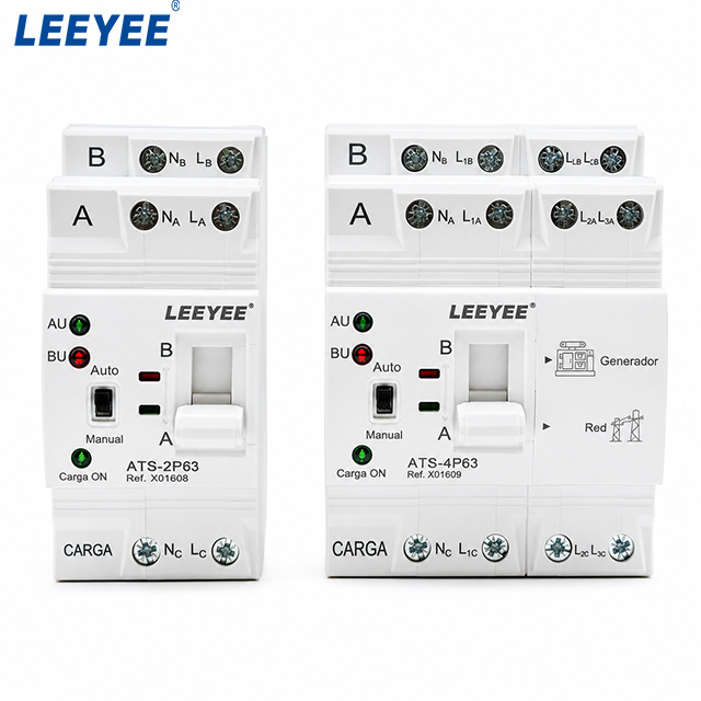
What still requires project confirmation: source arrangement, system voltage and frequency, required poles, load current, neutral treatment, upstream protection, available short-circuit information, acceptable transfer interruption, generator-start requirements and remote signalling.
In data-center-related projects, this compact ATS may be evaluated for suitable generator-backed distribution panels, auxiliary power circuits, equipment-room distribution and other circuits where the load can accept open transition or where the downstream architecture provides the required continuity.
It should not be treated as a universal replacement for closed-transition ATSE, bypass/isolation transfer equipment or static transfer systems. IEC 60947-6-1:2026 treats closed-transition and bypass/isolation functions as specific transfer-switching arrangements, while static transfer switches are covered separately by IEC 62310.[1][3]
If the project specification explicitly requires closed transition, bypass/isolation, STS or another specialized critical-power transfer architecture, do not substitute the compact open-transition ATS shown above only because its nominal voltage or current appears suitable. The required transfer architecture must be confirmed separately.
Before Ordering: Data Center ATS Project Checklist
A useful B2B enquiry should contain enough information to review the ATS inside the electrical system. “Need ATS for a data center” is not enough information for reliable model confirmation.
Prepare these project details
- Project single-line diagram
- Normal source type
- Emergency source type
- Tension du système
- System frequency
- Monophasé ou triphasé
- Design load current
- Required ATS poles
- Neutral switching requirement
- Grounding / earthing arrangement
- Generator neutral arrangement
- Dispositif de protection en amont
- Available short-circuit information
- UPS position
- Open transition acceptable: Yes / No / Unknown
- Generator-start requirement
- Required dry contacts
- BMS / PLC requirements
- Applicable project standard
- Destination country / local requirements
Send Your ATS Requirements for Review
Share the single-line diagram, source arrangement, voltage, design current, poles, UPS position and required control signals. These details allow LEEYEE to review whether the compact open-transition ATS product format is within the intended project scope.
Common Data Center ATS Selection Mistakes
| Erreur | Project risk | Approche plus appropriée |
|---|---|---|
| Selecting amperes first | Architecture and transfer requirements may be missed | Start with the single-line diagram |
| Assuming ATS means uninterrupted power | Open transition includes a source-disconnected interval | Check load tolerance and UPS position |
| Choosing 4P only because a neutral exists | Neutral treatment may not match the grounding design | Review source grounding and bonding |
| Checking only nominal current | Protection and fault requirements may be missed | Verify protection and short-circuit coordination |
| Adding BMS requirements after production | Required contacts or interfaces may not be available | Approve the I/O and communication requirements first |
Frequently Asked Engineering Questions
Can a compact open-transition ATS be used in a data center?
It can be evaluated where the actual downstream load and system architecture can accept the transfer interruption. An upstream ATS may also be part of an architecture with a downstream UPS, but the UPS location and ride-through design must be confirmed for the project.[2]
Does an ATS replace a UPS?
No. An ATS transfers a circuit between power sources, while a UPS has a different role in supporting its downstream load. They can work within the same backup-power architecture but are not substitutes for each other.[2][4]
Is 4P always required for a three-phase data center ATS?
No. The decision depends on whether the neutral must be switched and on the grounding and bonding arrangement of the sources. Confirm the actual system design rather than selecting 4P from phase count alone.[5][6]
Can the ATS current rating be selected from total data center capacity?
Not reliably. Use the electrical design of the circuit actually served by the ATS, then verify the selected model against the applicable voltage, load, protection and fault requirements.
Is an STS the same as an ATS?
No. IEC 60947-6-1:2026 excludes static transfer switches covered by the IEC 62310 series. STS should therefore be evaluated as a separate transfer technology when the project requires it.[1][3]
What should a buyer send for a data center ATS quotation?
Send the single-line diagram, source types, voltage, frequency, phase, design current, proposed poles, grounding arrangement, UPS position, acceptable transfer method, upstream protection and required remote signals. These parameters allow the ATS to be reviewed in its real system context.
Références
- International Electrotechnical Commission — IEC 60947-6-1:2026, Low-voltage switchgear and controlgear — Part 6-1: Multiple function equipment — Transfer switching equipment. Official IEC publication page confirming the scope for MTSE, RTSE, ATSE, bypass/isolation transfer switch equipment and ATSE with closed-transition capability. Official IEC source
- ABB — Applications for Data Centers: Transfer Switching / Automatic Transfer Switching for Redundant Power Systems in Data Centers. ABB technical material covering transfer switching in data-center power architectures and the relationship between transfer switching and downstream UPS systems. Official ABB source
- International Electrotechnical Commission — IEC 62310-1:2005, Static transfer systems (STS) — Part 1: General and safety requirements. Official IEC standard for AC static transfer systems intended to support continuity of load supply by controlled transfer between independent AC sources. Official IEC source
- Eaton — Fundamentals of Automatic Transfer Switches (ATS). Eaton technical guidance covering ATS operation, source monitoring, typical transfer sequences, source arrangements and transfer methods. Official Eaton source
- Schneider Electric / ASCO Power Technologies — Neutral Configurations in Transfer Switches, ASC-DB-NCTS. Technical data bulletin explaining solid-neutral and switched-neutral transfer-switch arrangements and their relationship to alternative-source grounding. Official Schneider Electric / ASCO source
- Schneider Electric / ASCO Power Technologies — Switching the Neutral Conductor, TS-WP-NEUTRALCON. Technical white paper discussing neutral switching and grounding considerations for generator transfer-switch applications. Official Schneider Electric / ASCO source
This guide is a B2B engineering selection reference, not a substitute for the project electrical design. Final ATS approval should use the current project specification, applicable local electrical requirements, single-line diagram, protection study and model-specific technical documentation.
