
Un chargeur rapide DC ne peut pas être protégé par un dispositif de protection contre les surtensions à l'entrée du cabinet. L'alimentation AC, le chemin DC haute tension, les lignes de données externes, les circuits de comptage et les commandes basse tension sont des interfaces électriques différentes. Chaque interface a besoin de sa propre vérification d'ingénierie.
Ce guide est rédigé pour les fabricants de chargeurs DC, les intégrateurs de stations de charge, les constructeurs de panneaux basse tension, les entrepreneurs EPC et les acheteurs OEM. Il se concentre spécifiquement sur les armoires de charge DC haute puissance, les systèmes de cabinets d'alimentation répartis/distributeurs et leurs circuits de contrôle connectés.
Table des matières
Réponse rapide : Passez en revue quatre zones de protection
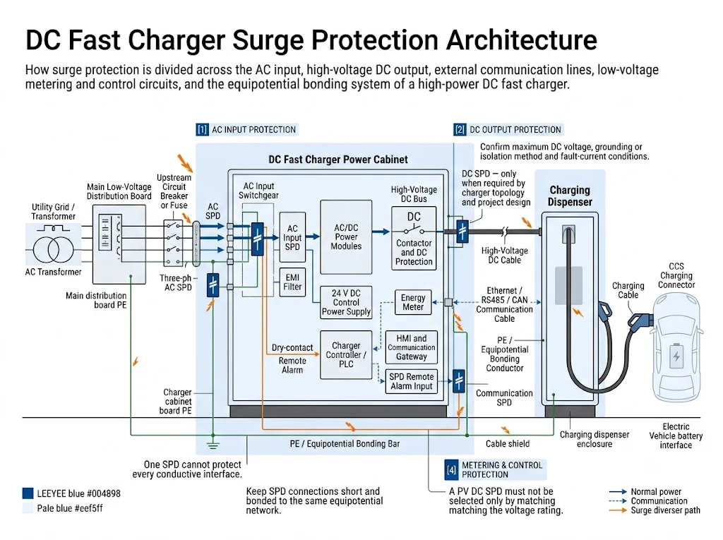
Révisez au moins quatre zones : l'entrée AC, tout circuit de sortie DC exposé ou requis par conception, les lignes de communication externes, et les circuits de comptage ou de contrôle.
L'entrée CA est normalement la première limite de protection. Un SPD à sortie CC n'est pas un besoin automatique. Son besoin et ses spécifications dépendent de la topologie du chargeur, de la tension maximale de fonctionnement en CC, de la relation avec la terre, de la surveillance de l'isolation, de l'exposition des câbles, des conditions de défaut en CC et des documents d'approbation du chargeur.
Quelle décision de protection vient en premier ?
La première décision dépend de la structure du chargeur. Cela empêche un chargeur intégré et un système de charge séparé d'être traités comme la même installation.
| Architecture du chargeur | Première décision de protection | Principal risque du projet |
|---|---|---|
| Chargeur intégré alimenté par CA | Confirmer l'entrée CA, les lignes de données externes et les interfaces de contrôle basse tension. Suivre le design du chargeur pour le court chemin interne en CC. | En supposant que l'SPD CA protège également chaque interface externe |
| Cabinet d'alimentation séparé et distributeur | Examiner chaque connexion CC, de communication et de mise à la terre entre les enceintes séparées. | Ignorer les longs câbles inter-armoires à l'extérieur |
| Un cabinet avec plusieurs distributeurs | Évaluer chaque branche sortante en fonction de la longueur du câble, du routage, de la mise à la terre et de l'isolation de maintenance. | Utiliser une évaluation de branche pour tous les distributeurs |
| Chargeur alimenté en CC ou lié au stockage | Confirmer la source CC en amont, la plage de tension, le comportement en cas de courant de défaut et les états de fonctionnement avant de sélectionner un SPD. | Appliquer les hypothèses d'un chargeur alimenté par CA |
Signification de l'acheteur : Le fait qu'un chargeur électrique fonctionne seul ne signifie pas qu'il sélectionne le SPD. Un chargeur de 180 kW et un chargeur de 360 kW peuvent nécessiter une protection différente en raison de leur tension, alimentation, topologie et agencement des câbles.
Pourquoi les chargeurs rapides DC ont-ils besoin d'une étude de protection séparée ?
Dans un point de charge AC, la plupart de la conversion d'énergie se fait à l'intérieur du véhicule. Un chargeur rapide DC réalise une conversion d'énergie à haute puissance à l'extérieur du véhicule et contrôle le transfert d'énergie DC directement vers le système de batterie.
La norme IEC 61851-23:2023 couvre les équipements de charge EV DC avec une tension maximale nominale allant jusqu'à 1 000 V AC ou 1 500 V DC du côté de l'alimentation et jusqu'à 1 500 V DC du côté du véhicule.[1] La communication numérique utilisée pour contrôler le transfert d'énergie DC est abordée en même temps que la norme IEC 61851-24:2023.[2]
Cette large plage de tension ne signifie pas que chaque chargeur haute puissance utilise le même circuit. Un cabinet intégré, un cabinet d'alimentation central alimentant plusieurs distributeurs et un chargeur alimenté en DC connecté à un stockage peuvent avoir des chemins de surtension très différents.
Chargeur intégré
L'entrée AC, les modules de conversion, le contrôleur et le terminal utilisateur se trouvent dans un même boîtier. Les câbles AC externes et de données sont généralement les premiers points à examiner.
Cabinet et distributeur séparés
Des câbles DC haute tension, de contrôle et de communication passent entre des enclosures séparées. Chaque câble inter-cabinet nécessite un examen d'exposition et de liaison.
Multiples distributeurs
Une armoire électrique dessert plusieurs bornes de recharge distantes. La longueur des dérivations, le tracé, la mise à la terre commune et l'isolation influencent le concept de protection.
Chargeur alimenté en courant continu
La source peut être un bus CC ou un système de stockage d'énergie. La plage de tension, les états bidirectionnels et le comportement en cas de défaut CC doivent être validés au cas par cas.
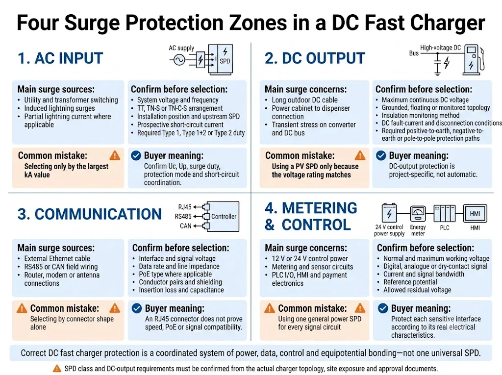
Cartographier les quatre zones de protection avant de sélectionner des modèles
Ces quatre zones sont soumises à des caractéristiques électriques, des normes et des contrôles de compatibilité différents. Les regrouper en une seule ligne de devis comporte des risques importants.
| Zone de protection | Exposition principale | Informations requises | Erreur courante |
|---|---|---|---|
| Entrée AC | Commutation des réseaux électriques, commutation des transformateurs, surtensions induites et intrusion éventuelle de courants de foudre | Tension alternative, système de mise à la terre, point d'installation, parasurtenseur en amont et conditions de court-circuit | Choisir uniquement entre Imax et la valeur kA la plus élevée |
| Sortie CC | Sollicitation du convertisseur ou du bus CC et longues connexions extérieures vers les distributeurs distants | Tension continue maximale, topologie, surveillance de l'isolation, modes de protection et conditions de défaut | Utiliser un SPD photovoltaïque uniquement parce que la tension semble correspondre |
| Communication | Câbles externes Ethernet, RS485, CAN, modem, antenne et câbles de raccordement entre la station et le réseau | Interface, tension, débit de données, PoE, conducteurs, blindage et mise à la terre | Sélection en fonction de la forme du connecteur uniquement |
| Mesure et contrôle | Alimentations 12/24 V, compteurs, E/S d'automates programmables, capteurs, interfaces homme-machine (IHM) et systèmes électroniques de paiement | Tension du circuit, type de signal, potentiel de référence et charge admissible sur l'interface | Utilisation d'un SPD d'alimentation général pour chaque circuit de signal |
Comment le SPD d'entrée AC doit-il être sélectionné ?
L'entrée CA constitue généralement le premier point de protection, car elle relie le chargeur au réseau de distribution du site. Le type et les caractéristiques nominales du parafoudre final doivent être conformes au concept de protection contre la foudre du site, à la configuration de l'alimentation et à la conception de l'entrée du chargeur.
1. Vérifiez l'emplacement d'installation
Vérifiez si le chargeur est raccordé à proximité du point d'entrée du réseau, à partir d'un tableau électrique dédié à la recharge des véhicules électriques ou à partir d'un tableau de distribution en aval. Notez la présence de tout dispositif de protection contre les surtensions (SPD) en amont ainsi que le tracé du câble entre les différents niveaux de protection.
2. Déterminer la capacité de pointe requise
Une protection de type 1 ou combinée de type 1+2 est envisagée lorsque le courant de foudre peut pénétrer à cet endroit. La protection de type 2 est couramment utilisée lorsque la conception tient compte des surtensions induites et de commutation, sans qu'une pénétration partielle du courant de foudre ne soit attendue.
Cette décision doit respecter les règles en vigueur en matière d'installation et de protection contre la foudre. Elle ne doit pas se fonder sur un seuil universel de puissance du chargeur.[5][6][7]
3. Vérifier les critères d'évaluation qui influent sur l'approbation
| Paramètres | Ce que cela change | Informations requises concernant le projet |
|---|---|---|
| Uc / MCOV | Le SPD doit supporter la tension continue maximale prévue en mode de protection. | Tension nominale, tolérance admissible, fréquence et système de mise à la terre |
| Haut / VPR | La tension maximale doit être adaptée à la résistance des équipements d'entrée du chargeur et des étages en aval. | Données relatives à la résistance des équipements, marché cible et exigences en matière de coordination |
| Iimp, In et Imax | Ces valeurs correspondent à différents niveaux de courant de pointe et ne sont pas interchangeables. | Type de SPD requis, classe d'essai et spécifications du projet en matière de surtensions |
| Isccr / SCCR | Le SPD et le sectionneur requis doivent être adaptés aux conditions de court-circuit prévues. | Courant de court-circuit prévisionnel et fusible ou disjoncteur en amont |
| Mode de protection | La configuration requise (L-N, L-PE ou N-PE) dépend du système d'alimentation et de mise à la terre. | TT, TN-S, TN-C-S ou autre configuration au point d'installation |
| Contact à distance | Permet au régulateur de charge ou au système du site de signaler un changement d'état du SPD | Capacité de charge des contacts, logique d'entrée de l'automate programmable et état d'alarme souhaité |
La norme CEI 61643-01:2024 définit les exigences communes applicables aux dispositifs de protection contre les surtensions (SPD). La norme CEI 61643-11:2025 s'applique aux dispositifs de protection contre les surtensions (SPD) raccordés aux réseaux d'alimentation basse tension en courant alternatif, tandis que la norme CEI 61643-12:2020 traite des principes de sélection, d'emplacement et de coordination des SPD en courant alternatif.[4][5][6]
Le sortie DC haute tension a-t-elle besoin d'un SPD ?
Pas automatiquement. La réponse dépend du cheminement du courant continu, de sa relation avec la terre ainsi que de la conception et de l'homologation du chargeur.
La norme CEI 61643-41:2025 définit les exigences et les méthodes d'essai applicables aux dispositifs de protection contre les surtensions (SPD) raccordés à des circuits d'alimentation en courant continu généraux et à des équipements d'une tension nominale maximale de 1 500 V CC.[8] Il s'agit d'une norme relative aux produits. Sa publication n'impose pas l'utilisation d'un SPD CC sur chaque sortie de chargeur.
La norme CEI 61643-41 prévoit également que toutes les exigences ne s'appliquent pas nécessairement à un appareil destiné exclusivement à une application électrique spécifique, telle qu'un circuit alimenté par une source non linéaire ou un circuit doté d'une séparation de protection. Cette détermination nécessite une évaluation des risques documentée et une analyse technique.[8]
Utilisez cette séquence de décision côté courant continu
- Identifiez la topologie du circuit continu. Vérifiez si la sortie est isolée, flottante, surveillée, référencée au point médian ou reliée intentionnellement à la terre.
- Enregistrez la tension continue maximale. Utilisez la tension de fonctionnement la plus élevée pour chaque mode de protection, et ne vous fiez pas uniquement à une indication telle que « chargeur 1 000 V ».
- Repérez le câble dénudé. Une courte liaison CC interne au sein d'une armoire est différente d'un long tracé extérieur reliant une armoire d'alimentation à un distributeur.
- Répertoriez les modes de protection possibles. Les contraintes « positif-à-terre », « négatif-à-terre » et « pôle-à-pôle » peuvent ne pas être identiques.
- Vérifier l'interaction entre le système de surveillance de l'isolation. Les composants de protection et de détection des fuites normales ne doivent pas provoquer de fausses alarmes ni compromettre le concept d'isolation.
- Vérifier la source de courant continu et le comportement en cas de défaut. Déterminer le courant de court-circuit prévu, les conditions de surtension temporaire et la méthode de coupure disponible.
- Consultez le dossier d'homologation du chargeur. L'ajout d'un SPD peut avoir une incidence sur les distances de sécurité, l'élévation de température, la compatibilité électromagnétique (CEM), le câblage et la nomenclature certifiée.
| Chemin CC | Mesures techniques | Raison |
|---|---|---|
| Lien interne court dans une annexe | Respectez la conception d'origine du chargeur. N'ajoutez pas automatiquement un dispositif de protection contre les surtensions (SPD) séparé. | Le convertisseur, le bus, les contacteurs et le système d'isolation peuvent déjà former un ensemble coordonné. |
| Armoire électrique pour distributeur à distance | Procéder à un examen spécifique portant sur l'exposition, la liaison et les SPD en courant continu. | Les conducteurs extérieurs de grande longueur peuvent traverser des zones de protection et relier des emplacements équipotentiels distincts. |
| Armoire centrale desservant plusieurs postes | Vérifiez chaque branche ainsi que la coordination au niveau des deux enclos. | La longueur du câble, son acheminement et l'isolation pour la maintenance peuvent varier selon le distributeur. |
| Chargeur alimenté en CC ou lié au stockage | Vérifiez les caractéristiques de la source, la plage de tension, le courant de défaut et les modes de fonctionnement bidirectionnels. | Il se peut qu'un convertisseur, une batterie ou un bus CC ne se comporte pas comme la source linéaire prise en compte dans les essais SPD standard. |
| Câble pour véhicule et interface de recharge | N'insérez pas de champ SPD générique sans l'accord du fabricant du chargeur. | La gestion du transfert de puissance, la communication, l'isolation et la compatibilité électromagnétique font partie intégrante de l'interface entre le chargeur et le véhicule. |
Signification technique : Un chargeur SPD à courant continu doit être considéré comme faisant partie intégrante du système électronique de puissance. Il ne peut pas être homologué simplement en faisant correspondre une tension et une valeur en kA figurant sur deux fiches techniques.
Pourquoi un SPD PV DC ne peut-il pas être reproduit dans un design de chargeur ?
La norme CEI 61643-31 s'applique aux dispositifs de protection contre les surtensions (SPD) conçus pour le côté courant continu des installations photovoltaïques jusqu'à 1 500 V CC.[9] La norme précise que les appareils conformes sont exclusivement destinés au côté courant continu des générateurs photovoltaïques et des onduleurs photovoltaïques. Les installations photovoltaïques équipées d'un système de stockage d'énergie ne sont pas couvertes par cette norme.[9]
La norme CEI 61643-41 porte sur les réseaux d'alimentation en courant continu à basse tension en général et exclut expressément de son champ d'application les parafoudres photovoltaïques.[8] Cette distinction est importante car un générateur photovoltaïque et la sortie d'un chargeur à convertisseur ne présentent pas les mêmes caractéristiques de source, le même comportement en cas de défaut ni la même interface avec les équipements.
Une mention de conformité à 1 000 V CC ou 1 500 V CC n'est pas suffisante. L'examen doit porter sur la norme applicable, les modes de protection, le comportement en cas de fuite, les caractéristiques de la source, les surtensions temporaires, les conditions de court-circuit, la méthode de déconnexion et le champ d'application de la certification du chargeur.
Comment protéger les lignes de données Ethernet, RS485, CAN et autres ?
Les lignes de données externes peuvent cesser de fonctionner même lorsque les modules d'alimentation principaux restent en bon état de fonctionnement. Parmi les interfaces conductrices courantes, on peut citer l'Ethernet de station, la mesure RS485, la communication de terrain CAN, les câbles coaxiaux de modem ou d'antenne, les équipements de paiement et les liaisons entre une armoire d'alimentation et un distributeur.
La norme CEI 61643-21:2025 s'applique aux dispositifs de protection contre les surtensions (SPD) raccordés aux réseaux de télécommunications et de signalisation. Son champ d'application inclut également les réseaux qui acheminent du courant sur les mêmes conducteurs, tels que le Power over Ethernet.[10] La norme CEI 61643-22:2015 traite des principes de sélection, de fonctionnement, d'implantation et de coordination de ces dispositifs de protection contre les surtensions (SPD).[11]
| Interface | Paramètres à vérifier | Erreur courante liée à l'approbation |
|---|---|---|
| Ethernet / RJ45 | Catégorie, débit, type de PoE, paires utilisées, blindage, perte d'insertion et mise à la terre | En supposant que chaque SPD RJ45 prenne en charge le débit requis et la puissance PoE |
| RS485 / Modbus | Tension de service, nombre de conducteurs, plage de mode commun, débit en bauds, blindage et format des bornes | Ne pas tenir compte du conducteur de référence ou utiliser un niveau de serrage inadapté |
| CAN | Tension du bus, débit de données, impédance de ligne, capacité admissible et brochage du connecteur | Utilisation d'un signal SPD générique qui surcharge ou perturbe le bus |
| Câble coaxial 4G/5G ou GNSS | Connecteur, impédance, bande de fréquences, perte d'insertion, passage du courant continu et mise à la masse de l'antenne | Sélectionner uniquement en fonction de l'aspect du connecteur |
| Impulsions de compteur et E/S numériques | Contact sec ou signal alimenté, tension, courant, potentiel de référence et exigences en matière de réponse | Considérer chaque borne basse tension comme étant du même type de signal |
Placez le dispositif SPD à proximité de l'interface protégée, à l'endroit où un câble conducteur externe pénètre dans l'enceinte. En cas de câble long reliant des armoires distinctes, la protection aux deux extrémités peut nécessiter une réévaluation, en tenant compte de la conception de la mise à la terre et des zones de protection contre la foudre.[11][12]
Protéger les circuits de comptage et de contrôle comme une zone séparée
Ce sont souvent de petits circuits auxiliaires qui sont à l'origine des pannes visibles : un IHM vide, une erreur de communication avec un compteur, un lecteur de carte indisponible, une réinitialisation du contrôleur ou une perte de connexion à distance.
Alimentation de contrôle
Alimentations 12 V ou 24 V CC pour contrôleurs, relais, ventilateurs, systèmes de régulation du refroidissement, capteurs et passerelles de communication.
Comptage
Circuits d'alimentation du compteur, de détection de tension ou de courant, de sortie d'impulsions et de communication RS485.
E/S de l'armoire
Interrupteurs de porte, système de surveillance de l'arrêt d'urgence, capteurs de température, alarmes de refroidissement par liquide et contacts auxiliaires.
Équipements des utilisateurs et du réseau
IHM, terminal de paiement, système de contrôle d'accès, routeur, modem, antenne externe et équipement de communication du site.
Sélectionnez le SPD à partir des données réelles du circuit : tension normale maximale, courant, type de signal, potentiel de référence, tension résiduelle admissible et bande passante de l'interface.
La norme IEEE C62.230-2022 considère l'infrastructure pour véhicules électriques comme un ensemble de circuits liés à l'alimentation électrique, à l'acquisition de données et à la communication.[15] La norme CEI 61851-21-2:2018 définit les exigences en matière de compatibilité électromagnétique (CEM) applicables aux systèmes de recharge externes pour véhicules électriques.[3] Tout SPD ajouté doit donc faire l’objet d’une évaluation tant au niveau de ses performances en cas de surtension que de sa compatibilité en fonctionnement normal.
La mise à la terre et le raccordement équipotentiel déterminent le niveau de protection réel
Un SPD limite la tension en détournant le courant de surtension vers un chemin défini. Une bonne valeur de résistance de mise à la terre ne suffit pas à elle seule à prouver que le chemin de surtension haute fréquence à l'intérieur du chargeur est court et efficace.
- Veillez à ce que les conducteurs de connexion SPD soient courts, directs et exempts de boucles inutiles.
- Veillez à séparer les conducteurs non protégés des conducteurs protégés lorsque la disposition de l'armoire le permet.
- Relier entre eux le boîtier du chargeur, la barre de mise à la terre, le dispositif de protection contre les surtensions (SPD), les blindages des câbles et les structures métalliques avoisinantes, conformément à un schéma coordonné.
- Ne créez pas une « terre SPD » distincte, isolée du réseau d’équipotentialité du chargeur.
- Vérifiez la mise à la terre tant au niveau de l'armoire électrique que du distributeur lorsque ceux-ci reposent sur des fondations distinctes.
- Vérifier que la terminaison du blindage est conforme aux exigences en matière de protection contre la foudre et de compatibilité électromagnétique.
La norme CEI 62305-4:2024 traite de la conception, de l'installation, de l'inspection, de la maintenance et des essais des dispositifs de protection contre les surtensions destinés aux systèmes électriques et électroniques au sein des bâtiments.[12] La norme CEI 60364-5-54 traite des dispositifs de mise à la terre, des conducteurs de protection et des conducteurs de liaison de protection.[13]
Signification de l'acheteur : Demandez le schéma de câblage de l'armoire et le schéma de mise à la terre, et pas seulement la fiche technique du parafoudre. Un parafoudre correctement dimensionné peut tout de même offrir une protection insuffisante si son chemin de raccordement est trop long ou mal acheminé.
L'alarme à distance doit conduire à une action de maintenance définie
Un contact à distance est utile pour les sites de recharge sans surveillance, mais il ne signale généralement que l'état fourni par ce SPD. Il ne vérifie pas le fusible en amont, le serrage des bornes, la connexion PE ni l'état des autres zones de protection.
Définissez la logique d'alarme avant de passer commande
- Vérifiez si le régulateur du chargeur fonctionne avec une logique de contacts normalement ouverts, normalement fermés ou inverseurs.
- Vérifiez les valeurs nominales de tension et de courant des contacts par rapport à l'automate programmable (PLC) ou au circuit d'E/S.
- Identifiez l'armoire et la zone de protection mentionnées dans le message d'alarme.
- Déterminez s’il convient également de détecter une rupture de continuité du câblage.
- Veuillez indiquer dans la liste des pièces de rechange le modèle exact du socle, du module enfichable et du modèle de remplacement homologué.
Définir ce qui se passe après une alarme
- Assurez-vous que l'équipement est en bon état de fonctionnement conformément à la procédure d'entretien du chargeur.
- Vérifiez l'indication du SPD et l'état des contacts à distance.
- Vérifier la protection de secours, les bornes, les conducteurs et la présence éventuelle de signes d'échauffement ou de contamination.
- Vérifiez les connexions PE et les liaisons équipotentielles.
- Ne remplacez ce composant que par un modèle ou un module homologué pour le projet.
- Enregistrez l'événement et testez le circuit d'alarme avant de remettre le chargeur en service.
Les intervalles d'inspection et les critères de remplacement doivent respecter les recommandations du fabricant du chargeur, la documentation du parafoudre, l'exposition du site et les règles de maintenance locales. Il ne faut pas appliquer un intervalle de remplacement universel à tous les projets de recharge rapide.
Les limites d'assemblage et de certification doivent rester claires
Pour les fabricants d'armoires électriques, l'ajout d'un SPD ne se résume pas à une simple décision d'achat de composants. L'ensemble complet doit en effet respecter les exigences applicables en matière d'élévation de température, de résistance aux courts-circuits, de circuits de protection, de distances de sécurité, de câblage et de conditions d'encastrement.
La norme CEI 61439-7:2022 couvre les ensembles destinés à des applications telles que les bornes de recharge pour véhicules électriques, avec une tension nominale pouvant atteindre 1 000 V CA ou 1 500 V CC.[14] Les exigences relatives aux équipements de recharge et celles en matière de compatibilité électromagnétique (CEM) continuent de constituer des volets distincts du processus global d'homologation.[1][3]
Erreurs courantes de conception et d'approvisionnement
Un seul SPD protège l'ensemble du chargeur
Le SPD d'entrée CA ne protège pas automatiquement un câble Ethernet distant, une liaison de distributeur ou un signal de terrain 24 V.
La puissance du chargeur détermine le SPD
La puissance nominale en kW ne définit pas la tension Uc, le mode de protection, la résistance aux courts-circuits ni la compatibilité de communication.
Une valeur de kA plus élevée est toujours synonyme de meilleure performance
Les valeurs nominales de courant de surtension doivent être considérées conjointement avec le type de dispositif de protection contre les surtensions (SPD), le niveau de protection, la tension du réseau et la coordination.
Tout projet nécessite les types 1 et 2
La charge nominale requise dépend de l'exposition au courant de foudre, du point d'alimentation et du concept de protection en amont.
Un SPD photovoltaïque est suffisamment proche
Une tension continue correspondante ne garantit pas la compatibilité avec la sortie d'un chargeur alimenté par convertisseur.
La gestion à distance élimine les besoins en maintenance
Le contact de statut ne vérifie pas les fusibles, les bornes, les liaisons, l'humidité ni les dommages thermiques.
Flux de confirmation OEM SPD pour chargeurs rapides DC
Un devis utile commence par les données du système, et non par une photo du produit. Le processus ci-dessous distingue les informations relatives au chargeur, les quatre vérifications des zones de protection et la validation finale du document.

Informations à fournir avant la sélection du modèle
- Puissance nominale du chargeur
- Nombre de modules de puissance et de sorties
- Structure de meuble monobloc ou en deux parties
- Tension et fréquence d'entrée CA
- Dispositif de mise à la terre du courant alternatif
- Courant de court-circuit prospectif
- Fusible ou disjoncteur en amont
- Système de protection contre la foudre externe
- SPD en amont existant
- Tension de sortie CC maximale
- Courant de sortie CC maximal
- Caractéristiques de la source de courant continu
- Méthode de mise à la terre ou d'isolation en courant continu
- Dispositif de surveillance de l'isolation
- Courant de défaut en courant continu prévu
- Conditions de surtension temporaires
- Distance entre l'armoire électrique et le distributeur
- Acheminement des câbles à l'extérieur
- Interfaces Ethernet, RS485, CAN et coaxiales
- Exigences relatives au PoE et au débit de données
- Circuits de commande 12/24 V
- Exigences relatives aux contacts d'alarme à distance
- Homologations IEC, EN, UL ou nationales requises
- Pays d'installation et environnement
- Exigences d'étiquetage et d'emballage OEM
Vous avez besoin d'une analyse SPD spécifique à un projet ?
Veuillez nous envoyer le schéma unifilaire, les tensions maximales CA et CC, les caractéristiques de la source d'alimentation, la structure de l'armoire, les longueurs de câbles et la liste des interfaces. LEEYEE pourra utiliser ces informations pour élaborer un modèle et établir un rapport de validation dans le cadre du projet de chargeur.
Questions fréquentes sur l'approvisionnement
Est-ce que chaque chargeur rapide en courant continu doit être équipé d'un SPD côté courant continu ?
Il n'existe pas de règle universelle applicable à toutes les topologies. Vérifiez la tension continue maximale, les caractéristiques de la source, le rapport à la terre, la surveillance de l'isolation, l'exposition des câbles, les conditions de défaut et les documents d'homologation du chargeur. Une longue liaison extérieure vers un bornier distant nécessite un examen différent de celui d'une courte connexion interne en courant continu.
Un parafoudre PV conforme à la norme IEC 61643-31 peut-il être utilisé dans un chargeur rapide CC ?
La conformité à la norme CEI 61643-31 ne suffit pas à elle seule à démontrer l'adéquation du produit. Cette norme concerne spécifiquement le côté courant continu (CC) des générateurs photovoltaïques et des onduleurs. Une application de chargeur nécessite une attestation d'adéquation distincte fournie par le fabricant de l'appareil, ainsi que l'agrément de l'équipementier (OEM) du chargeur.
La certification CEI 61643-41 est-elle suffisante pour choisir un parafoudre CC ?
Non. La norme CEI 61643-41 définit les exigences relatives aux produits et les essais à effectuer, mais ses hypothèses d’essai standard prévoient une source présentant une caractéristique tension-courant linéaire. Un chargeur alimenté par un convertisseur nécessite tout de même une validation du courant de défaut, des contraintes de surtension temporaires, de la déconnexion et des limites d’homologation de l’équipement.
L'entrée CA doit-elle être de type 1+2 ou de type 2 ?
La réponse dépend de l'intensité du courant de foudre au point d'installation. Avant de choisir le type de parasurtenseur, il convient d'examiner le système externe de protection contre la foudre, le chemin d'alimentation entrant, l'emplacement de l'installation, le parasurtenseur en amont et les réglementations nationales applicables.
Un SPD RJ45 suffit-il pour la communication avec le chargeur ?
Uniquement si cela correspond à la catégorie Ethernet, à la vitesse, aux exigences PoE, au blindage et au schéma de mise à la terre réels. Les interfaces RS485, CAN, coaxiales et d'E/S de commande nécessitent une protection spécifique à chaque type d'interface.
Où les parafoudres de signal doivent-ils être installés ?
Ils sont généralement placés à proximité de l'interface protégée, à l'endroit où un câble conducteur externe pénètre dans l'enceinte. Les liaisons longues entre des armoires distinctes peuvent nécessiter une protection et une mise à la terre coordonnées aux deux extrémités.
Quels documents un acheteur OEM doit-il demander ?
Demandez la fiche technique spécifique au modèle, la norme applicable, le certificat d'essai ou le périmètre du rapport d'essai, les caractéristiques de protection, les conditions de court-circuit, les instructions relatives à la protection de secours, les données de contact à distance et le manuel d'installation. Vérifiez que le modèle et la configuration exacts sont bien compatibles avec le projet de chargeur.
Conclusion finale sur l'ingénierie et l'approvisionnement
Un concept complet de protection contre les surtensions pour les chargeurs rapides à courant continu ne se résume pas simplement à « un dispositif de protection contre les surtensions (SPD) en courant alternatif plus un SPD en courant continu ». Il s'agit d'une analyse coordonnée de toutes les interfaces conductrices, depuis le tableau électrique du site jusqu'à l'armoire du chargeur, en passant par le distributeur à distance, le système de commande et le réseau externe.
Commencez par la topologie du chargeur. Vérifiez séparément les conditions de courant alternatif et de courant continu. Adaptez les SPD de communication et de contrôle aux interfaces réelles. Vérifiez ensuite la liaison, le comportement de la source, la coordination en cas de court-circuit, les contraintes temporaires de surtension, l'alarme à distance et les limites de certification avant de valider la nomenclature finale.
Références
- IEC, IEC 61851-23:2023, Système de recharge par conduction pour véhicules électriques – Partie 23 : Équipements d'alimentation en courant continu pour véhicules électriques. Page de publication officielle de l'IEC.
- IEC, IEC 61851-24:2023, Système de recharge par conduction pour véhicules électriques – Partie 24 : Communication numérique entre l'équipement d'alimentation CC d'un véhicule électrique et un véhicule électrique pour la commande de la recharge en courant continu. Page de publication officielle de l'IEC.
- IEC, IEC 61851-21-2:2018, Système de recharge par conduction pour véhicules électriques – Partie 21-2 : Exigences de compatibilité électromagnétique (CEM) pour les systèmes de recharge externes des véhicules électriques. Page de publication officielle de l'IEC.
- IEC, IEC 61643-01:2024, Dispositifs de protection contre les surtensions à basse tension – Partie 01 : Exigences générales et méthodes d'essai. Page de publication officielle de l'IEC.
- IEC, IEC 61643-11:2025, Dispositifs de protection contre les surtensions à basse tension – Partie 11 : Dispositifs de protection contre les surtensions (SPD) raccordés aux réseaux d'alimentation à basse tension en courant alternatif. Page de publication officielle de l'IEC.
- IEC, IEC 61643-12:2020, Dispositifs de protection contre les surtensions à basse tension – Partie 12 : Dispositifs de protection contre les surtensions (SPD) raccordés aux réseaux d'alimentation à basse tension en courant alternatif – Principes de sélection et d'application. Page de publication officielle de l'IEC.
- IEC, IEC 60364-5-53:2019 avec les amendements 1:2020 et 2:2024, Installations électriques à basse tension – Partie 5-53 : Appareils de protection, d’isolement, de commutation, de commande et de surveillance. Page officielle des publications consolidées de la CEI.
- IEC, IEC 61643-41:2025, Dispositifs de protection contre les surtensions à basse tension – Partie 41 : Dispositifs de protection contre les surtensions (SPD) raccordés à des réseaux d'alimentation à basse tension en courant continu – Exigences et méthodes d'essai. Page de publication officielle de l'IEC.
- IEC, IEC 61643-31:2018, Dispositifs de protection contre les surtensions à basse tension – Partie 31 : Exigences et méthodes d'essai applicables aux dispositifs de protection contre les surtensions (SPD) destinés aux installations photovoltaïques. Page de publication officielle de l'IEC.
- IEC, IEC 61643-21:2025, Dispositifs de protection contre les surtensions à basse tension – Partie 21 : Dispositifs de protection contre les surtensions (SPD) raccordés aux réseaux de télécommunications et de signalisation – Exigences et méthodes d'essai. Page de publication officielle de l'IEC.
- IEC, IEC 61643-22:2015, Dispositifs de protection contre les surtensions à basse tension – Partie 22 : Principes de sélection et d'application pour les réseaux de télécommunications et de signalisation. Page de publication officielle de l'IEC.
- IEC, IEC 62305-4:2024, Protection contre la foudre – Partie 4 : Systèmes électriques et électroniques au sein des ouvrages. Page de publication officielle de l'IEC.
- IEC, IEC 60364-5-54:2011 avec l'amendement 1:2021, Installations électriques à basse tension – Partie 5-54 : Dispositifs de mise à la terre et conducteurs de protection. Page officielle des publications consolidées de la CEI.
- IEC, IEC 61439-7:2022, Ensembles d’appareillage de commutation et de commande à basse tension – Partie 7 : Ensembles destinés notamment aux stations de recharge de véhicules électriques. Page de publication officielle de l'IEC.
- Association des normes de l'IEEE, IEEE C62.230-2022, Guide IEEE pour la protection contre les surtensions des infrastructures destinées aux véhicules électriques. Page officielle consacrée aux normes IEEE.
