
Um carregador rápido DC não pode ser protegido por um único dispositivo de proteção contra surtos na entrada do gabinete. A alimentação CA, o caminho DC de alta tensão, linhas de dados externas, circuitos de medição e controles de baixa tensão são interfaces elétricas diferentes. Cada interface precisa de sua própria verificação de engenharia.
Este guia é escrito para fabricantes de carregadores DC, integradores de estações de carregamento, construtores de painéis de baixa tensão, contratantes EPC e compradores de OEM. Ele se concentra especificamente em gabinetes de carregamento DC de alta potência, sistemas de gabinete de energia separado / dispensador e seus circuitos de controle conectados.
Índice
Resposta Rápida: Revisar Quatro Zonas de Proteção
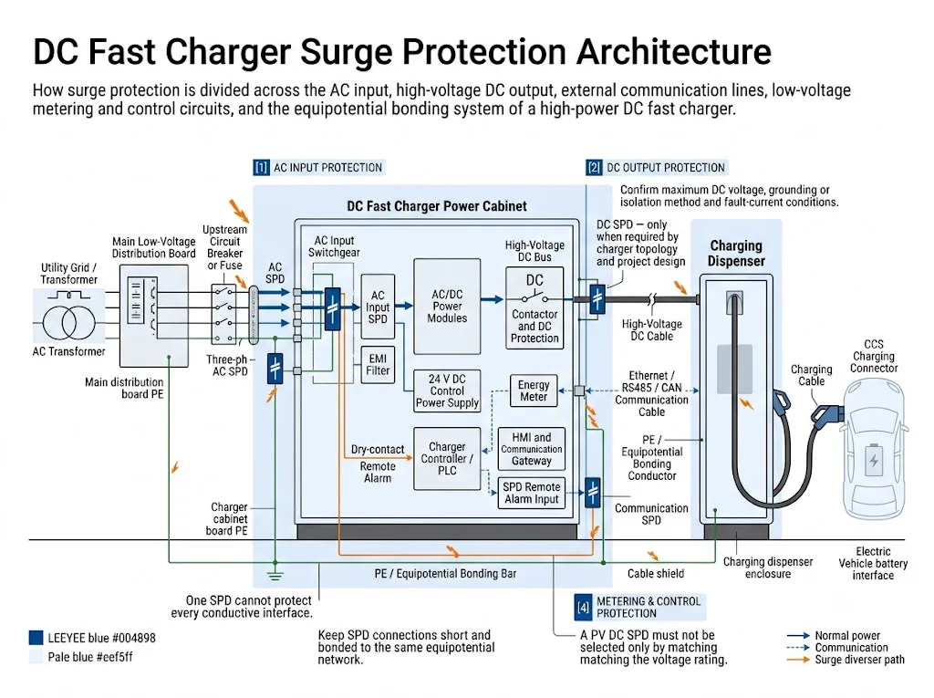
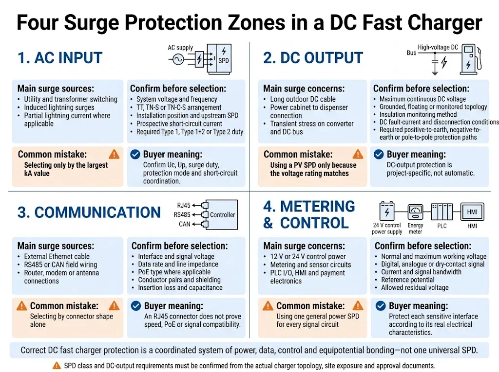
Revise pelo menos quatro zonas: a entrada CA, qualquer circuito de saída DC exposto ou requerido pelo design, linhas de comunicação externas e circuitos de medição ou controle.
A entrada de CA é normalmente a primeira fronteira de proteção. Um SPD de saída CC não é um requisito automático. Sua necessidade e classificações dependem da topologia do carregador, da tensão máxima de operação em CC, da relação com a terra, do monitoramento de isolamento, da exposição dos cabos, das condições de falha em CC e dos documentos de aprovação do carregador.
Qual Decisão de Proteção Vem Primeiro?
A primeira decisão depende da estrutura do carregador. Isso impede que um carregador integrado e um sistema de carregamento dividido sejam tratados como a mesma instalação.
| Arquitetura do carregador | Primeira decisão de proteção | Principal risco do projeto |
|---|---|---|
| Carregador alimentado por CA integrado | Confirme a entrada de CA, as linhas de dados externas e as interfaces de controle de baixa tensão. Siga o design do carregador para o curto caminho interno de CC. | Supondo que o SPD de CA também proteja cada interface externa |
| Gabinete de potência dividido e dispenser | Revise cada conexão de CC, comunicação e aterramento entre os diferentes gabinetes. | Ignorando cabos intercabinetes longos ao ar livre |
| Um gabinete com múltiplos dispensers | Avalie cada ramificação de saída de acordo com o comprimento do cabo, o roteamento, o aterramento e a isolação de manutenção. | Usando uma avaliação de ramificação para todos os dispensers |
| Carregador alimentado por CC ou conectado a armazenamento | Confirme a fonte de CC a montante, a faixa de tensão, o comportamento da corrente de falha e os estados de operação antes de selecionar um SPD. | Aplicando suposições de um carregador alimentado por CA |
Significado do comprador: A potência do carregador sozinha não seleciona o SPD. Um carregador de 180 kW e um de 360 kW ainda podem exigir proteção diferente porque sua voltagem, fornecimento, topologia e arranjo de cabos são diferentes.
Por que Carregadores Rápidos DC Precisam de um Estudo de Proteção Separado
Em um ponto de carga AC, a maior parte da conversão de potência permanece dentro do veículo. Um carregador rápido DC realiza a conversão de alta potência fora do veículo e controla a transferência de energia DC diretamente para o sistema da bateria.
A IEC 61851-23:2023 abrange equipamentos de fornecimento de veículos elétricos DC com tensão máxima nominal de até 1.000 V AC ou 1.500 V DC no lado de fornecimento e até 1.500 V DC no lado do veículo.[1] A comunicação digital utilizada para controlar a transferência de energia DC é abordada em conjunto com a IEC 61851-24:2023.[2]
Esse amplo intervalo de tensão não significa que todo carregador de alta potência utilize o mesmo circuito. Um gabinete integrado, um gabinete central de potência alimentando vários dispensadores e um carregador alimentado por DC conectado ao armazenamento podem ter caminhos de surto muito diferentes.
Carregador integrado
A entrada AC, os módulos de conversão, o controlador e o terminal do usuário estão em um único enclosure. Cabos externos AC e de dados são geralmente os primeiros pontos de revisão.
Gabinete dividido e dispensador
Cabos de controle e comunicação DC de alta tensão correm entre gabinetes separados. Cada cabo inter-gabinete precisa de uma revisão de exposição e aterramento.
Múltiplos dispensadores
One power cabinet serves several remote charging posts. Branch length, route, common bonding and isolation affect the protection concept.
DC-fed charger
The source may be a DC bus or energy-storage system. Voltage range, bidirectional states and DC fault behaviour require project confirmation.
Mapear as Quatro Zonas de Proteção Antes de Selecionar Modelos
The four zones use different electrical ratings, standards and compatibility checks. Combining them into one quotation line hides important risks.
| Protection zone | Main exposure | Informações necessárias | Typical mistake |
|---|---|---|---|
| entrada CA | Utility switching, transformer switching, induced surges and possible lightning-current entry | AC voltage, earthing system, installation point, upstream SPD and short-circuit conditions | Choosing only from Imax or the largest kA value |
| DC output | Converter or DC-bus stress and long outdoor connections to remote dispensers | Maximum DC voltage, topology, insulation monitoring, protection modes and fault conditions | Using a PV SPD only because the voltage appears to match |
| Communication | External Ethernet, RS485, CAN, modem, antenna and station-network cables | Interface, voltage, data rate, PoE, conductors, shield and grounding | Selecting by connector shape alone |
| Metering and control | 12/24 V supplies, meters, PLC I/O, sensors, HMI and payment electronics | Circuit voltage, signal type, reference potential and permitted interface loading | Using one general power SPD for every signal circuit |
Como o SPD de Entrada CA Deve Ser Selecionado?
The AC input is normally the first protection location because it connects the charger to the site distribution system. The final SPD type and ratings must follow the site lightning-protection concept, supply arrangement and charger input design.
1. Confirm the installation position
Identify whether the charger is connected near the service entrance, from a dedicated EV charging switchboard or from a downstream distribution panel. Record any upstream SPD and the cable route between protection stages.
2. Determine the required surge duty
Type 1 or combined Type 1+2 protection is considered where lightning current can enter at that location. Type 2 protection is commonly used where the design addresses induced and switching surges without expected partial lightning-current entry.
The decision must follow the applicable installation and lightning-protection rules. It should not be based on a universal charger-power threshold.[5][6][7]
3. Verify the ratings that affect approval
| Parâmetro | What it changes | Project information needed |
|---|---|---|
| Uc / MCOV | The SPD must tolerate the highest continuous voltage expected in its protection mode | Nominal voltage, permitted variation, frequency and earthing system |
| Up / VPR | The limited voltage must coordinate with the withstand of charger input equipment and downstream stages | Equipment withstand data, target market and coordination requirements |
| Iimp, In and Imax | These values describe different surge-current duties and are not interchangeable | Required SPD type, test class and project surge specification |
| Isccr / SCCR | The SPD and required disconnector must be suitable for the available short-circuit conditions | Prospective short-circuit current and upstream fuse or breaker |
| Modo de proteção | The required L-N, L-PE or N-PE arrangement depends on the supply and earthing system | TT, TN-S, TN-C-S or other arrangement at the installation point |
| Contato remoto | Allows the charger controller or site system to report a change in SPD status | Contact rating, PLC input logic and desired alarm state |
IEC 61643-01:2024 provides common SPD requirements. IEC 61643-11:2025 applies to SPDs connected to AC low-voltage power systems, while IEC 61643-12:2020 covers AC SPD selection, location and coordination principles.[4][5][6]
O Saída DC de Alta Tensão Precisa de um SPD?
Not automatically. The answer depends on where the DC path runs, how it relates to earth and how the charger has been designed and approved.
IEC 61643-41:2025 provides requirements and test methods for SPDs connected to general DC power circuits and equipment rated up to 1,500 V DC.[8] It is a product standard. Its publication does not make a DC SPD mandatory at every charger output.
IEC 61643-41 also allows that not every requirement will necessarily apply to a device intended only for a specific power application, such as a circuit supplied by a nonlinear source or a circuit with protective separation. That determination requires a documented risk assessment and engineering review.[8]
Use this DC-side decision sequence
- Identify the DC topology. Confirm whether the output is isolated, floating, monitored, midpoint referenced or intentionally connected to earth.
- Record the maximum continuous voltage. Use the highest operating voltage for each protection mode, not only a label such as “1,000 V charger”.
- Locate the exposed cable. A short internal DC link inside one cabinet is different from a long outdoor route between a power cabinet and dispenser.
- Map the possible protection modes. Positive-to-earth, negative-to-earth and pole-to-pole stress may not be identical.
- Confirm insulation-monitoring interaction. Normal leakage and protection components must not cause false alarms or undermine the insulation concept.
- Check DC source and fault behaviour. Determine the expected short-circuit current, temporary overvoltage conditions and available disconnection method.
- Review the charger approval file. An added SPD can affect clearances, temperature rise, EMC, wiring and the certified bill of materials.
| DC path | Engineering action | Razão |
|---|---|---|
| Short internal link in one enclosure | Follow the charger OEM design. Do not add a separate SPD automatically. | The converter, bus, contactors and insulation system may already form one coordinated assembly. |
| Power cabinet to remote dispenser | Perform a dedicated exposure, bonding and DC SPD review. | Long outdoor conductors can cross protection zones and connect separate equipotential locations. |
| Central cabinet serving several posts | Review each branch and the coordination at both enclosures. | Cable length, routing and maintenance isolation may differ by dispenser. |
| Carregador alimentado por CC ou conectado a armazenamento | Confirm the source characteristic, voltage range, fault current and bidirectional operating states. | A converter, battery or DC bus may not behave like the linear source assumed by standard SPD tests. |
| Vehicle cable and charging interface | Do not insert a generic field SPD without charger-manufacturer approval. | Power-transfer control, communication, insulation and EMC form part of the charger/vehicle interface. |
Engineering meaning: a charger DC SPD must be treated as part of the power-electronic system. It cannot be approved only by matching a voltage and kA value on two datasheets.
Por que um SPD DC de PV Não Pode Ser Copiado para um Projeto de Carregador
IEC 61643-31 applies to SPDs designed for the DC side of photovoltaic installations up to 1,500 V DC.[9] The standard states that compliant devices are exclusively dedicated to the DC side of photovoltaic generators and photovoltaic inverters. PV systems with energy storage are not covered by that standard.[9]
IEC 61643-41 covers general DC low-voltage power systems and specifically excludes PV SPDs from its scope.[8] This distinction matters because a photovoltaic array and a converter-controlled charger output do not have the same source characteristic, fault behaviour or equipment interface.
A matching 1,000 V DC or 1,500 V DC marking is not enough. The review must cover the applicable standard, protection modes, leakage behaviour, source characteristic, temporary overvoltage stress, short-circuit conditions, disconnection method and charger certification scope.
Como Proteger Linhas de Dados como Ethernet, RS485, CAN e Outras?
External data lines can stop charging even when the main power modules remain healthy. Typical conductive interfaces include station Ethernet, RS485 metering, CAN field communication, modem or antenna coax, payment equipment and links between a power cabinet and dispenser.
IEC 61643-21:2025 applies to SPDs connected to telecommunications and signalling networks. Its scope also includes networks that carry power on the same conductors, such as Power over Ethernet.[10] IEC 61643-22:2015 covers selection, operation, location and coordination principles for these SPDs.[11]
| Interface | Parâmetros a verificar | Common approval error |
|---|---|---|
| Ethernet / RJ45 | Category, data rate, PoE type, pairs used, shield, insertion loss and grounding | Assuming every RJ45 SPD supports the required speed and PoE power |
| RS485 / Modbus | Working voltage, conductor count, common-mode range, baud rate, shield and terminal format | Ignoring the reference conductor or using the wrong clamping level |
| CAN | Bus voltage, data rate, line impedance, permitted capacitance and connector pinout | Using a generic signal SPD that loads or distorts the bus |
| 4G/5G or GNSS coax | Connector, impedance, frequency range, insertion loss, DC pass and antenna bonding | Selecting only from connector appearance |
| Meter pulse and digital I/O | Dry contact or powered signal, voltage, current, reference potential and response requirements | Treating every low-voltage terminal as the same signal type |
Place the signal SPD close to the protected interface where an external conductive cable enters the enclosure. For a long cable between separate cabinets, protection at both ends may require review together with the bonding design and lightning-protection zones.[11][12]
Proteger Circuitos de Medição e Controle como uma Zona Separada
Small auxiliary circuits often cause the visible outage: a blank HMI, meter communication error, unavailable card reader, controller reset or lost remote connection.
Potência de controle
12 V or 24 V DC supplies for controllers, relays, fans, cooling controls, sensors and communication gateways.
Metering
Meter supply, voltage or current sensing, pulse output and RS485 communication circuits.
Cabinet I/O
Door switches, emergency-stop monitoring, temperature sensors, liquid-cooling alarms and auxiliary contacts.
User and network equipment
HMI, payment terminal, access control, router, modem, external antenna and site communication equipment.
Select the SPD from the real circuit data: maximum normal voltage, current, signal type, reference potential, permitted residual voltage and interface bandwidth.
IEEE C62.230-2022 treats EV infrastructure as a combination of power, data-acquisition and communication-related circuitry.[15] IEC 61851-21-2:2018 covers EMC requirements for off-board EV charging systems.[3] Any added SPD should therefore be reviewed for both surge performance and normal-operation compatibility.
Aterramento e Ligação Equipotencial Determinam o Nível Real de Proteção
An SPD limits voltage by diverting surge current through a defined path. A good earth-resistance value alone does not prove that the high-frequency surge path inside the charger is short and effective.
- Keep SPD connection conductors short, direct and free from unnecessary loops.
- Keep unprotected conductors separated from protected conductors where the cabinet layout permits.
- Bond the charger enclosure, PE bar, SPD, cable shields and nearby metallic systems according to one coordinated design.
- Do not create a separate “SPD earth” isolated from the charger equipotential network.
- Review bonding at both the power cabinet and dispenser when they stand on separate foundations.
- Confirm shield termination from both lightning-protection and EMC requirements.
IEC 62305-4:2024 addresses the design, installation, inspection, maintenance and testing of surge-protection measures for electrical and electronic systems within structures.[12] IEC 60364-5-54 addresses earthing arrangements, protective conductors and protective bonding conductors.[13]
Significado do comprador: request the cabinet wiring drawing and bonding concept, not only an SPD datasheet. A correctly rated SPD can still provide poor protection when its connection path is long or badly routed.
Alarme Remoto Deve Levar a uma Ação de Manutenção Definida
A remote contact is useful for unattended charging sites, but it normally reports only the status state provided by that SPD. It does not verify the upstream fuse, terminal tightness, PE connection or the condition of other protection zones.
Define the alarm logic before ordering
- Confirm whether the charger controller expects normally open, normally closed or changeover contact logic.
- Check the contact voltage and current rating against the PLC or I/O circuit.
- Identify the cabinet and protection zone in the alarm message.
- Decide whether loss of wiring continuity should also be detected.
- Include the exact base, plug-in module and approved replacement model in the spare-parts list.
Define what happens after an alarm
- Make the equipment safe according to the charger maintenance procedure.
- Inspect the SPD indication and remote-contact state.
- Check backup protection, terminals, conductors and signs of heating or contamination.
- Verify PE and bonding connections.
- Replace only with the project-approved model or module.
- Record the event and test the alarm circuit before returning the charger to service.
Inspection intervals and replacement criteria must follow the charger manufacturer, SPD documentation, site exposure and local maintenance rules. One universal replacement interval should not be applied to every fast-charging project.
Limites de Montagem e Certificação Devem Permanecer Claros
For panel builders, adding an SPD is not only a component-purchasing decision. The complete assembly still has to meet the applicable requirements for temperature rise, short-circuit withstand, protective circuits, clearances, wiring and enclosure conditions.
IEC 61439-7:2022 includes assemblies for applications such as electric vehicle charging stations with rated voltage up to 1,000 V AC or 1,500 V DC.[14] Charger equipment requirements and EMC requirements remain separate parts of the complete approval process.[1][3]
Erros Comuns de Design e Aquisição
One SPD protects the whole charger
The AC input SPD does not automatically protect a remote Ethernet cable, dispenser link or 24 V field signal.
Charger power selects the SPD
Rated kW does not define Uc, protection mode, short-circuit withstand or communication compatibility.
Higher kA always means better
Surge-current ratings must be read together with SPD type, protection level, system voltage and coordination.
Every project needs Type 1+2
The required duty depends on lightning-current exposure, the supply point and the upstream protection concept.
A PV SPD is close enough
A matching DC voltage does not demonstrate suitability for a converter-fed charger output.
Remote contact removes maintenance
The status contact does not inspect fuses, terminals, bonding, moisture or thermal damage.
Fluxo de Confirmação do OEM do SPD para Carregador Rápido DC
A useful quotation begins with system data, not a product photo. The workflow below separates the charger information, the four protection-zone reviews and the final document approval.

Information to send before model selection
- Charger rated power
- Number of power modules and outputs
- Integrated or split cabinet structure
- AC input voltage and frequency
- AC earthing arrangement
- Corrente de curto-circuito prospectiva
- Upstream fuse or breaker
- External lightning protection system
- Existing upstream SPD
- Maximum DC output voltage
- Maximum DC output current
- DC source characteristic
- DC grounding or isolation method
- Insulation monitoring arrangement
- Expected DC fault current
- Temporary overvoltage conditions
- Power-cabinet to dispenser distance
- Outdoor cable routing
- Ethernet, RS485, CAN and coax interfaces
- PoE and data-rate requirements
- 12/24 V control circuits
- Remote-alarm contact requirements
- Required IEC, EN, UL or national approvals
- Installation country and environment
- Requisitos de rotulagem e embalagem de OEM
Need a project-specific SPD review?
Send the single-line diagram, maximum AC and DC voltages, source characteristics, cabinet structure, cable distances and interface list. LEEYEE can use these inputs to prepare a model and document confirmation for the charger project.
Perguntas Frequentes sobre Aquisição
Does every DC fast charger need a DC-side SPD?
No universal rule applies to every topology. Confirm the maximum DC voltage, source characteristic, relationship to earth, insulation monitoring, cable exposure, fault conditions and charger approval documents. A long outdoor link to a remote dispenser requires a different review from a short internal DC connection.
Can an IEC 61643-31 PV SPD be used in a DC fast charger?
IEC 61643-31 compliance alone does not demonstrate suitability. The standard is specifically for the DC side of photovoltaic generators and inverters. A charger application requires separate documented suitability from the device manufacturer and approval from the charger OEM.
Is IEC 61643-41 certification enough to select the DC SPD?
No. IEC 61643-41 provides product requirements and tests, but its standard test assumptions include a source with a linear voltage-current characteristic. A converter-fed charger still requires confirmation of fault current, temporary overvoltage stress, disconnection and the equipment approval boundary.
Should the AC input use Type 1+2 or Type 2?
The answer depends on the lightning-current duty at the installation point. Review the external lightning protection system, incoming supply route, installation location, upstream SPD and applicable national rules before fixing the SPD type.
Is an RJ45 SPD enough for charger communication?
Only when it matches the actual Ethernet category, speed, PoE requirement, shielding and grounding arrangement. RS485, CAN, coax and control I/O need interface-specific protection.
Where should signal SPDs be installed?
They are normally placed close to the protected interface where an external conductive cable enters the enclosure. Long links between separate cabinets may require coordinated protection and bonding at both ends.
What documents should an OEM buyer request?
Request the model-specific datasheet, applicable standard, test certificate or report scope, protection-mode ratings, short-circuit conditions, backup-protection instructions, remote-contact data and installation manual. Confirm that the exact model and configuration are accepted for the charger project.
Conclusão Final de Engenharia e Aquisição
A complete DC fast charger surge-protection concept is not simply “one AC SPD plus one DC SPD”. It is a coordinated review of every conductive interface from the site switchboard to the charger cabinet, remote dispenser, control system and external network.
Start with the charger topology. Confirm the AC and DC conditions separately. Match communication and control SPDs to the real interfaces. Then verify bonding, source behaviour, short-circuit coordination, temporary overvoltage stress, remote alarm and certification boundaries before approving the final bill of materials.
Referências
- IEC, IEC 61851-23:2023, Electric vehicle conductive charging system – Part 23: DC electric vehicle supply equipment. Página de publicação oficial da IEC.
- IEC, IEC 61851-24:2023, Electric vehicle conductive charging system – Part 24: Digital communication between DC EV supply equipment and an electric vehicle for control of DC charging. Página de publicação oficial da IEC.
- IEC, IEC 61851-21-2:2018, Electric vehicle conductive charging system – Part 21-2: EMC requirements for off-board electric vehicle charging systems. Página de publicação oficial da IEC.
- IEC, IEC 61643-01:2024, Low-voltage surge protective devices – Part 01: General requirements and test methods. Página de publicação oficial da IEC.
- IEC, IEC 61643-11:2025, Low-voltage surge protective devices – Part 11: SPDs connected to AC low-voltage power systems. Página de publicação oficial da IEC.
- IEC, IEC 61643-12:2020, Low-voltage surge protective devices – Part 12: SPDs connected to AC low-voltage power systems – Selection and application principles. Página de publicação oficial da IEC.
- IEC, IEC 60364-5-53:2019 with Amendments 1:2020 and 2:2024, Low-voltage electrical installations – Part 5-53: Devices for protection, isolation, switching, control and monitoring. Official IEC consolidated publication page.
- IEC, IEC 61643-41:2025, Low-voltage surge protective devices – Part 41: SPDs connected to DC low-voltage power systems – Requirements and test methods. Página de publicação oficial da IEC.
- IEC, IEC 61643-31:2018, Low-voltage surge protective devices – Part 31: Requirements and test methods for SPDs for photovoltaic installations. Página de publicação oficial da IEC.
- IEC, IEC 61643-21:2025, Low-voltage surge protective devices – Part 21: SPDs connected to telecommunications and signalling networks – Requirements and test methods. Página de publicação oficial da IEC.
- IEC, IEC 61643-22:2015, Low-voltage surge protective devices – Part 22: Selection and application principles for telecommunications and signalling networks. Página de publicação oficial da IEC.
- IEC, IEC 62305-4:2024, Protection against lightning – Part 4: Electrical and electronic systems within structures. Página de publicação oficial da IEC.
- IEC, IEC 60364-5-54:2011 with Amendment 1:2021, Low-voltage electrical installations – Part 5-54: Earthing arrangements and protective conductors. Official IEC consolidated publication page.
- IEC, IEC 61439-7:2022, Low-voltage switchgear and controlgear assemblies – Part 7: Assemblies for applications including electric vehicle charging stations. Página de publicação oficial da IEC.
- IEEE Standards Association, IEEE C62.230-2022, IEEE Guide for Surge Protection of Electric Vehicle Infrastructure. Official IEEE standard page.
