
Un caricabatterie rapido DC non può essere protetto da un solo dispositivo di protezione da sovratensioni all'ingresso del cabinet. L'alimentazione CA, il percorso DC ad alta tensione, le linee dati esterne, i circuiti di misurazione e i controlli a bassa tensione sono interfacce elettriche diverse. Ogni interfaccia necessita di un proprio controllo ingegneristico.
Questa guida è scritta per i produttori di caricabatterie DC, gli integratori di stazioni di ricarica, i costruttori di pannelli a bassa tensione, i contraenti EPC e gli acquirenti OEM. Si concentra specificamente sugli armadi di ricarica DC ad alta potenza, sui sistemi di armadi/erogatori a potenza separata e sui loro circuiti di controllo connessi.
Indice dei contenuti
Risposta veloce: Rivedi quattro zone di protezione
Rivedere almeno quattro zone: l'ingresso CA, qualsiasi circuito di uscita DC esposto o richiesto dal design, le linee di comunicazione esterne e i circuiti di misurazione o controllo.
L'ingresso AC è normalmente il primo confine di protezione. Un SPD a uscita DC non è un requisito automatico. La sua necessità e i requisiti dipendono dalla topologia del caricabatterie, dalla tensione operativa DC massima, dalla relazione con la terra, dal monitoraggio dell'isolamento, dall'esposizione dei cavi, dalle condizioni di guasto DC e dai documenti di approvazione del caricabatterie.
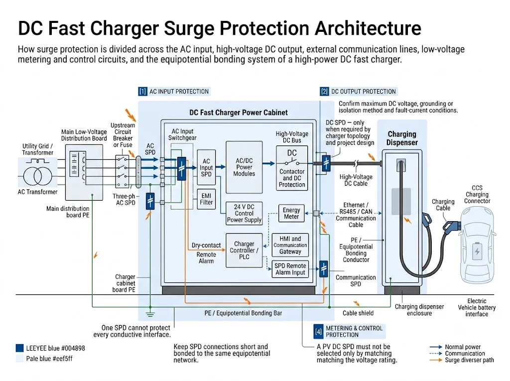
Quale decisione di protezione viene prima?
La prima decisione dipende dalla struttura del caricabatterie. Questo impedisce che un caricabatterie integrato e un sistema di ricarica suddiviso siano trattati come la stessa installazione.
| Architettura del caricabatterie | Prima decisione di protezione | Principale rischio di progetto |
|---|---|---|
| Caricabatterie alimentato da AC integrato | Confermare l'ingresso AC, le linee di dati esterne e le interfacce di controllo a bassa tensione. Seguire il design del caricabatterie per il breve percorso DC interno. | Presumendo che l'SPD AC protegga anche ogni interfaccia esterna |
| Cabinet di alimentazione e dispenser separati | Esaminare ogni connessione DC, di comunicazione e di legami tra le diverse casse. | Ignorando i cavi lunghi all'aperto tra le cabine |
| Un cabinet con più dispenser | Valutare ogni ramo in uscita in base alla lunghezza del cavo, al percorso, ai legami e all'isolamento per la manutenzione. | Utilizzando una valutazione del ramo per tutti i dispenser |
| Caricabatterie alimentato da DC o collegato a stoccaggio | Confermare la fonte DC a monte, il range di tensione, il comportamento della corrente di guasto e gli stati operativi prima di selezionare un SPD. | Applicando assunzioni da un caricabatterie alimentato da AC |
Significato dell'acquirente: la potenza del caricatore da sola non seleziona il SPD. Un caricatore da 180 kW e un caricatore da 360 kW possono comunque richiedere una protezione diversa poiché la loro tensione, fornitura, topologia e disposizione dei cavi sono diverse.
Perché i caricabatterie DC rapidi necessitano di uno studio di protezione separato
In un punto di ricarica AC, gran parte della conversione di potenza rimane all'interno del veicolo. Un caricatore rapido DC esegue la conversione ad alta potenza all'esterno del veicolo e controlla il trasferimento di energia DC direttamente al sistema della batteria.
IEC 61851-23:2023 copre le attrezzature di alimentazione per veicoli elettrici DC con tensione massima nominale fino a 1.000 V AC o 1.500 V DC sul lato di alimentazione e fino a 1.500 V DC sul lato del veicolo.[1] La comunicazione digitale utilizzata per controllare il trasferimento di energia DC è trattata insieme a IEC 61851-24:2023.[2]
Questa ampia gamma di tensione non significa che ogni caricatore ad alta potenza utilizzi lo stesso circuito. Un armadio integrato, un armadio di alimentazione centrale che alimenta diversi distributori e un caricatore alimentato in DC collegato a uno stoccaggio possono avere percorsi di sovratensione molto diversi.
Caricatore integrato
L'ingresso AC, i moduli di conversione, il controllore e il terminale dell'utente sono in un'unica custodia. I cavi AC esterni e i cavi dati sono solitamente i primi punti di revisione.
Armadio e distributore separati
Cavi di comunicazione, controllo e DC ad alta tensione corrono tra custodie separate. Ogni cavo inter-cabina necessita di una revisione dell'esposizione e del collegamento.
Distributori multipli
Un unico quadro di alimentazione serve più punti di ricarica remoti. La lunghezza del ramo, il tracciato, il collegamento equipotenziale comune e l’isolamento influenzano il concetto di protezione.
Caricabatterie alimentato in c.c.
La sorgente può essere un bus in c.c. o un sistema di accumulo di energia. L’intervallo di tensione, gli stati bidirezionali e il comportamento ai guasti in c.c. richiedono conferma del progetto.
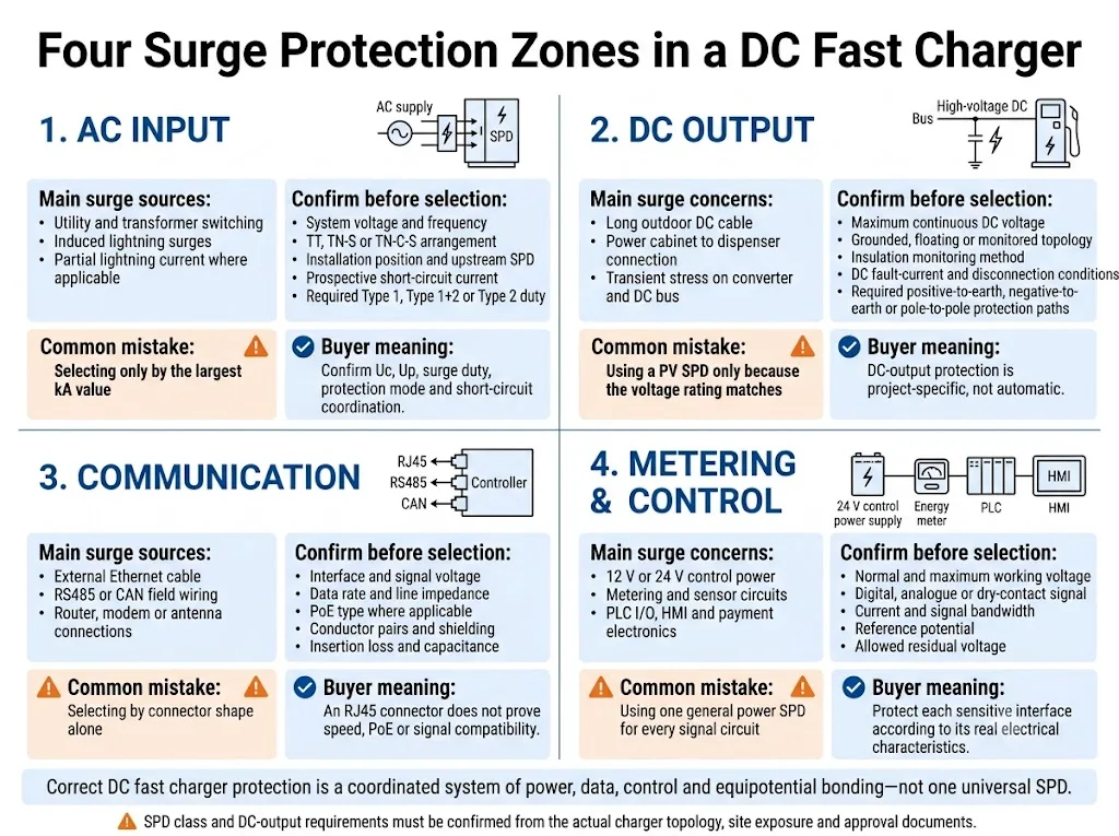
Mappa le quattro zone di protezione prima di selezionare i modelli
Le quattro zone utilizzano valori nominali elettrici, norme e verifiche di compatibilità diversi. Combinarle in un’unica riga di offerta nasconde rischi importanti.
| Zona di protezione | Esposizione principale | Informazioni richieste | Errore tipico |
|---|---|---|---|
| Ingresso AC | Commutazione dell’utenza, commutazione del trasformatore, sovratensioni indotte e possibile ingresso di correnti da fulmine | Tensione c.a., sistema di messa a terra, punto di installazione, SPD a monte e condizioni di cortocircuito | Scegliere solo in base a Imax o al valore kA più elevato |
| Uscita c.c. | Sollecitazioni del convertitore o del bus in c.c. e lunghi collegamenti esterni verso dispenser remoti | Tensione massima in c.c., topologia, monitoraggio dell’isolamento, modalità di protezione e condizioni di guasto | Usare solo uno SPD per fotovoltaico perché la tensione sembra corrispondere |
| Comunicazione | Ethernet esterna, RS485, CAN, modem, antenna e cavi della rete di stazione | Interfaccia, tensione, velocità dati, PoE, conduttori, schermo e messa a terra | Scegliere in base alla sola forma del connettore |
| Misurazione e controllo | Alimentazioni 12/24 V, contatori, I/O PLC, sensori, HMI ed elettronica di pagamento | Tensione del circuito, tipo di segnale, potenziale di riferimento e carico d’interfaccia consentito | Utilizzo di un unico SPD di alimentazione generale per ogni circuito di segnale |
Come dovrebbe essere selezionato l'SPD in ingresso CA?
L’ingresso AC è normalmente il primo punto di protezione, perché collega il caricabatterie al sistema di distribuzione del sito. Il tipo e le caratteristiche nominali finali dell’SPD devono seguire il concetto di protezione contro i fulmini del sito, la configurazione dell’alimentazione e il progetto dell’ingresso del caricabatterie.
1. Confermare la posizione di installazione
Identificare se il caricabatterie è collegato in prossimità dell’ingresso del servizio, da un quadro dedicato per la ricarica EV oppure da un quadro di distribuzione a valle. Registrare l’eventuale SPD a monte e il percorso del cavo tra i livelli di protezione.
2. Determinare il livello di sollecitazione da sovratensione richiesto
La protezione di Tipo 1 o combinata Tipo 1+2 è considerata quando la corrente di fulmine può entrare in quel punto. La protezione di Tipo 2 è comunemente utilizzata quando il progetto affronta sovratensioni indotte e di manovra senza prevedere l’ingresso di corrente di fulmine parziale.
La decisione deve seguire le norme applicabili di installazione e protezione contro i fulmini. Non deve basarsi su una soglia universale di potenza del caricabatterie.[5][6][7]
3. Verificare le caratteristiche nominali che influenzano l’approvazione
| Parametro | Cosa modifica | Informazioni di progetto richieste |
|---|---|---|
| Uc / MCOV | L’SPD deve tollerare la massima tensione continua prevista nella sua modalità di protezione | Tensione nominale, variazione consentita, frequenza e sistema di messa a terra |
| Su / VPR | La tensione limitata deve coordinarsi con la tenuta dell’apparecchiatura d’ingresso del caricabatterie e degli stadi a valle | Dati di tenuta dell’apparecchiatura, mercato di destinazione e requisiti di coordinamento |
| Iimp, In e Imax | Questi valori descrivono diverse condizioni di corrente di sovratensione e non sono intercambiabili | Tipo di SPD richiesto, classe di prova e specifica di sovratensione del progetto |
| Isccr / SCCR | L'SPD e il sezionatore richiesto devono essere idonei alle condizioni di cortocircuito disponibili | Corrente di cortocircuito prospettica e fusibile o interruttore a monte |
| Modalità di protezione | La configurazione L-N, L-PE o N-PE richiesta dipende dal sistema di alimentazione e di messa a terra | TT, TN-S, TN-C-S o altra configurazione nel punto di installazione |
| Contatto remoto | Consente al controller del caricatore o al sistema del sito di segnalare una variazione dello stato dell'SPD | Portata dei contatti, logica di ingresso PLC e stato di allarme desiderato |
IEC 61643-01:2024 fornisce i requisiti comuni per gli SPD. IEC 61643-11:2025 si applica agli SPD collegati ai sistemi di alimentazione in c.a. a bassa tensione, mentre IEC 61643-12:2020 copre i principi di selezione, ubicazione e coordinamento degli SPD in c.a.[4][5][6]
L'uscita DC ad alta tensione necessita di un SPD?
Non automaticamente. La risposta dipende da dove corre il percorso DC, come si relaziona alla terra e come il caricabatterie è stato progettato e approvato.
La IEC 61643-41:2025 fornisce requisiti e metodi di test per SPD collegati a circuiti di alimentazione DC generici e apparecchiature con tensione nominale fino a 1.500 V DC.[8] È uno standard di prodotto. La sua pubblicazione non rende obbligatorio un SPD DC su ogni uscita del caricabatterie.
La IEC 61643-41 consente inoltre che non tutti i requisiti si applichino necessariamente a un dispositivo destinato solo a un'applicazione di potenza specifica, come un circuito alimentato da una sorgente non lineare o un circuito con separazione protettiva. Tale determinazione richiede una valutazione del rischio documentata e una revisione tecnica.[8]
Utilizzare questa sequenza decisionale lato DC
- Identificare la topologia DC. Confermare se l'uscita è isolata, flottante, monitorata, con riferimento al punto centrale o intenzionalmente collegata a terra.
- Registrare la tensione massima continua. Utilizzare la tensione operativa più alta per ogni modalità di protezione, non solo un'etichetta come “caricabatterie da 1.000 V”.
- Individuare il cavo esposto. Un breve collegamento DC interno all'interno di un armadio è diverso da un lungo percorso esterno tra un armadio di alimentazione e un erogatore.
- Mappare le possibili modalità di protezione. Lo stress positivo-verso-terra, negativo-verso-terra e polo-polo potrebbe non essere identico.
- Confermare l'interazione con il monitoraggio dell'isolamento. La dispersione normale e i componenti di protezione non devono causare falsi allarmi o compromettere il concetto di isolamento.
- Controllare la sorgente DC e il comportamento in caso di guasto. Determinare la corrente di cortocircuito prevista, le condizioni di sovratensione temporanea e il metodo di disconnessione disponibile.
- Revisionare il fascicolo di approvazione del caricabatterie. Un SPD aggiunto può influenzare le distanze, l'aumento di temperatura, l'EMC, il cablaggio e la distinta base certificata.
| Percorso CC | Intervento ingegneristico | Motivo |
|---|---|---|
| Breve collegamento interno in un unico involucro | Seguire il design dell'OEM del caricabatterie. Non aggiungere automaticamente un SPD separato. | Il convertitore, il bus, i contattori e il sistema di isolamento potrebbero già formare un unico assemblaggio coordinato. |
| Armadio di alimentazione verso erogatore remoto | Eseguire una revisione dedicata dell'esposizione, del collegamento equipotenziale e dell'SPD DC. | I conduttori esterni lunghi possono attraversare zone di protezione e collegare posizioni equipotenziali separate. |
| Armadio centrale a servizio di diverse postazioni | Revisionare ogni ramo e il coordinamento presso entrambi gli involucri. | La lunghezza del cavo, l'instradamento e l'isolamento per la manutenzione possono differire a seconda dell'erogatore. |
| Caricabatterie alimentato da DC o collegato a stoccaggio | Confermare la caratteristica della sorgente, l'intervallo di tensione, la corrente di guasto e gli stati operativi bidirezionali. | Un convertitore, una batteria o un bus DC potrebbero non comportarsi come la sorgente lineare presunta dai test SPD standard. |
| Cavo del veicolo e interfaccia di ricarica | Non inserire un SPD generico da campo senza l'approvazione del produttore del caricabatterie. | Il controllo del trasferimento di potenza, la comunicazione, l'isolamento e la compatibilità elettromagnetica (EMC) fanno parte dell'interfaccia caricabatterie/veicolo. |
Significato ingegneristico: Un SPD DC per caricabatterie deve essere trattato come parte del sistema di elettronica di potenza. Non può essere approvato solo confrontando i valori di tensione e kA su due schede tecniche.
Perché un SPD DC per PV non può essere copiato in un design di caricabatterie
La norma IEC 61643-31 si applica agli SPD progettati per il lato DC degli impianti fotovoltaici fino a 1.500 V DC.[9] La norma stabilisce che i dispositivi conformi sono dedicati esclusivamente al lato DC dei generatori fotovoltaici e degli inverter fotovoltaici. Gli impianti fotovoltaici con accumulo di energia non sono coperti da tale norma.[9]
La norma IEC 61643-41 copre i sistemi di alimentazione DC a bassa tensione generici ed esclude specificamente dal suo ambito di applicazione gli SPD per fotovoltaico.[8] Questa distinzione è importante perché un array fotovoltaico e l'uscita di un caricabatterie controllato da convertitore non presentano le stesse caratteristiche di sorgente, comportamento in caso di guasto o interfaccia con l'apparecchiatura.
Un valore nominale di 1.000 V DC o 1.500 V DC non è sufficiente. La valutazione deve coprire la norma applicabile, i modi di protezione, il comportamento della corrente di dispersione, la caratteristica della sorgente, lo stress da sovratensione temporanea, le condizioni di cortocircuito, il metodo di disconnessione e l'ambito di certificazione del caricabatterie.
Come dovrebbero essere protette le linee dati Ethernet, RS485, CAN e altre?
Le linee dati esterne possono interrompere la ricarica anche quando i moduli di alimentazione principali rimangono integri. Le interfacce conduttive tipiche includono Ethernet della stazione, misurazione RS485, comunicazione di campo CAN, modem o antenna coassiale, dispositivi di pagamento e collegamenti tra armadio di alimentazione e colonnina.
La norma IEC 61643-21:2025 si applica agli SPD collegati a reti di telecomunicazione e segnalazione. Il suo campo di applicazione include anche reti che trasportano energia sugli stessi conduttori, come il Power over Ethernet.[10] La norma IEC 61643-22:2015 copre i principi di selezione, funzionamento, posizionamento e coordinamento per questi SPD.[11]
| Interfaccia | Parametri da verificare | Errore di approvazione comune |
|---|---|---|
| Ethernet / RJ45 | Categoria, velocità dati, tipo PoE, coppie utilizzate, schermatura, perdita di inserzione e messa a terra | Presumere che ogni SPD RJ45 supporti la velocità e la potenza PoE richieste |
| RS485 / Modbus | Tensione di esercizio, numero di conduttori, range di modo comune, baud rate, schermatura e formato dei terminali | Ignorare il conduttore di riferimento o utilizzare un livello di clamping errato |
| CAN | Tensione del bus, velocità dati, impedenza di linea, capacità consentita e piedinatura del connettore | Utilizzare un SPD di segnale generico che carichi o distorca il bus |
| Coassiale 4G/5G o GNSS | Connettore, impedenza, intervallo di frequenza, perdita di inserzione, passaggio DC e collegamento di messa a terra dell'antenna | Selezionare solo in base all'aspetto del connettore |
| Impulso del contatore e I/O digitale | Contatto pulito o segnale alimentato, tensione, corrente, potenziale di riferimento e requisiti di risposta | Trattare ogni terminale a bassa tensione come se fosse lo stesso tipo di segnale |
Posizionare l'SPD di segnale vicino all'interfaccia protetta dove un cavo conduttivo esterno entra nell'involucro. Per un cavo lungo tra armadi separati, la protezione alle due estremità può richiedere una revisione congiunta con il progetto di collegamento equipotenziale e le zone di protezione contro i fulmini.[11][12]
Proteggi i circuiti di misurazione e controllo come una zona separata
Piccoli circuiti ausiliari spesso causano l'interruzione visibile: un HMI spento, errore di comunicazione del contatore, lettore di carte non disponibile, reset del controller o connessione remota persa.
Alimentazione di controllo
Alimentazioni 12 V o 24 V DC per controller, relè, ventole, controlli di raffreddamento, sensori e gateway di comunicazione.
Misurazione
Alimentazione del contatore, rilevamento di tensione o corrente, uscita impulsi e circuiti di comunicazione RS485.
I/O dell'armadio
Interruttori porta, monitoraggio arresto di emergenza, sensori di temperatura, allarmi di raffreddamento a liquido e contatti ausiliari.
Apparecchiature utente e di rete
HMI, terminale di pagamento, controllo accessi, router, modem, antenna esterna e apparecchiature di comunicazione del sito.
Selezionare l'SPD in base ai dati reali del circuito: tensione nominale massima, corrente, tipo di segnale, potenziale di riferimento, tensione residua consentita e larghezza di banda dell'interfaccia.
La norma IEEE C62.230-2022 tratta l'infrastruttura EV come una combinazione di circuiti di alimentazione, acquisizione dati e comunicazione.[15] La norma IEC 61851-21-2:2018 copre i requisiti EMC per i sistemi di ricarica EV fuori bordo.[3] Ogni SPD aggiunto dovrebbe quindi essere valutato sia per le prestazioni contro le sovratensioni che per la compatibilità con il funzionamento normale.
La messa a terra e il legame equipotenziale determinano il livello reale di protezione
Un SPD limita la tensione deviando la corrente di sovratensione attraverso un percorso definito. Un buon valore di resistenza di terra da solo non prova che il percorso di sovratensione ad alta frequenza all'interno del caricabatterie sia breve ed efficace.
- Mantenere i conduttori di collegamento dell'SPD brevi, diretti e privi di anelli non necessari.
- Mantenere i conduttori non protetti separati dai conduttori protetti ove il layout dell'armadio lo consenta.
- Collegare l'involucro del caricabatterie, la barra PE, l'SPD, le schermature dei cavi e i sistemi metallici vicini secondo un unico progetto coordinato.
- Non creare una "terra SPD" separata isolata dalla rete equipotenziale del caricabatterie.
- Revisionare il collegamento equipotenziale sia nell'armadio di alimentazione che nella colonnina quando poggiano su fondamenta separate.
- Confermare la terminazione della schermatura sia in base ai requisiti di protezione contro i fulmini che a quelli EMC.
La norma IEC 62305-4:2024 riguarda la progettazione, l'installazione, l'ispezione, la manutenzione e il collaudo delle misure di protezione contro le sovratensioni per sistemi elettrici ed elettronici all'interno delle strutture.[12] La norma IEC 60364-5-54 riguarda gli impianti di messa a terra, i conduttori di protezione e i conduttori di collegamento di protezione.[13]
Significato dell'acquirente: richiedere il disegno del cablaggio dell'armadio e il concetto di collegamento equipotenziale, non solo una scheda tecnica dell'SPD. Un SPD correttamente dimensionato può comunque fornire una protezione scarsa quando il suo percorso di collegamento è lungo o instradato male.
L'allarme remoto deve portare a un'azione di manutenzione definita
Un contatto remoto è utile per i siti di ricarica non presidiati, ma normalmente segnala solo lo stato fornito dall'SPD stesso. Non verifica il fusibile a monte, il serraggio dei terminali, il collegamento PE o le condizioni di altre zone di protezione.
Definire la logica di allarme prima di effettuare l'ordine
- Confermare se il controller del caricabatterie richiede una logica di contatto normalmente aperto, normalmente chiuso o di scambio.
- Verificare la tensione e la corrente nominale del contatto rispetto al circuito PLC o I/O.
- Identificare l'armadio e la zona di protezione nel messaggio di allarme.
- Decidere se debba essere rilevata anche la perdita di continuità del cablaggio.
- Includere la base esatta, il modulo plug-in e il modello sostitutivo approvato nella distinta base dei ricambi.
Definire cosa succede dopo un allarme
- Mettere in sicurezza l'apparecchiatura secondo la procedura di manutenzione del caricabatterie.
- Ispezionare l'indicazione dell'SPD e lo stato del contatto remoto.
- Controllare la protezione di backup, i terminali, i conduttori e i segni di surriscaldamento o contaminazione.
- Verificare i collegamenti di protezione e messa a terra.
- Sostituire solo con il modello o il modulo approvato per il progetto.
- Registrare l'evento e testare il circuito di allarme prima di rimettere in servizio il caricabatterie.
Gli intervalli di ispezione e i criteri di sostituzione devono seguire le indicazioni del produttore del caricabatterie, la documentazione dell'SPD, l'esposizione del sito e le norme di manutenzione locali. Non si dovrebbe applicare un intervallo di sostituzione universale a ogni progetto di ricarica rapida.
I confini di assemblaggio e certificazione devono rimanere chiari
Per i costruttori di quadri, l'aggiunta di un SPD non è solo una decisione di acquisto di componenti. L'assemblaggio completo deve comunque soddisfare i requisiti applicabili per aumento di temperatura, tenuta al cortocircuito, circuiti di protezione, distanze di isolamento, cablaggio e condizioni dell'involucro.
La norma IEC 61439-7:2022 include assemblaggi per applicazioni come le stazioni di ricarica per veicoli elettrici con tensione nominale fino a 1.000 V AC o 1.500 V DC.[14] I requisiti delle apparecchiature di ricarica e i requisiti EMC rimangono parti separate del processo di approvazione completo.[1][3]
Errori comuni nel design e nell'approvvigionamento
Un unico SPD protegge l'intero caricabatterie
L'SPD di ingresso AC non protegge automaticamente un cavo Ethernet remoto, un collegamento al distributore o un segnale di campo a 24 V.
La potenza del caricabatterie seleziona l'SPD
I kW nominali non definiscono Uc, il modo di protezione, la tenuta al cortocircuito o la compatibilità della comunicazione.
Un valore di kA più alto significa sempre migliore
I valori nominali di corrente di scarica devono essere letti insieme al tipo di SPD, al livello di protezione, alla tensione di sistema e al coordinamento.
Ogni progetto necessita di Tipo 1+2
Il servizio richiesto dipende dall'esposizione alla corrente di fulmine, dal punto di alimentazione e dal concetto di protezione a monte.
Un SPD fotovoltaico è sufficientemente vicino
Una tensione DC corrispondente non dimostra l'idoneità per un'uscita del caricabatterie alimentata da convertitore.
Il contatto remoto elimina la manutenzione
Il contatto di stato non ispeziona fusibili, terminali, collegamento equipotenziale, umidità o danni termici.
Flusso di lavoro di conferma dell'SPD OEM per caricabatterie DC rapidi
Un preventivo utile inizia con i dati di sistema, non con la foto di un prodotto. Il flusso di lavoro seguente separa le informazioni sul caricabatterie, le revisioni delle quattro zone di protezione e l'approvazione finale del documento.

Informazioni da inviare prima della selezione del modello
- Potenza nominale del caricabatterie
- Numero di moduli di potenza e uscite
- Struttura dell'armadio integrata o separata
- Tensione e frequenza di ingresso AC
- Schema di collegamento a terra AC
- Corrente di cortocircuito presunta
- Fusibile o interruttore a monte
- Sistema di protezione esterno contro i fulmini
- SPD esistente a monte
- Tensione massima di uscita DC
- Corrente massima di uscita DC
- Caratteristica della sorgente DC
- Metodo di messa a terra o isolamento DC
- Schema di monitoraggio dell'isolamento
- Corrente di guasto DC prevista
- Condizioni di sovratensione temporanea
- Distanza tra l'armadio di potenza e il distributore
- Percorso del cavo esterno
- Interfacce Ethernet, RS485, CAN e coassiali
- Requisiti PoE e velocità dati
- Circuiti di controllo 12/24 V
- Requisiti per contatti di allarme remoto
- Approvazioni IEC, EN, UL o nazionali richieste
- Paese di installazione e ambiente
- Requisiti per etichette e imballaggio OEM
Hai bisogno di una revisione SPD specifica per il progetto?
Inviare lo schema unifilare, le tensioni massime CA e CC, le caratteristiche della sorgente, la struttura dell'armadio, le distanze dei cavi e l'elenco delle interfacce. LEEYEE può utilizzare questi input per preparare un modello e la conferma documentale per il progetto del caricabatterie.
Domande frequenti sull'approvvigionamento
Ogni caricabatterie rapido CC necessita di un SPD sul lato CC?
Non esiste una regola universale valida per ogni topologia. Verificare la tensione CC massima, le caratteristiche della sorgente, il riferimento a terra, il monitoraggio dell'isolamento, l'esposizione dei cavi, le condizioni di guasto e i documenti di approvazione del caricabatterie. Un collegamento esterno lungo verso un distributore remoto richiede una valutazione diversa rispetto a una breve connessione CC interna.
È possibile utilizzare un SPD PV IEC 61643-31 in un caricabatterie rapido CC?
La sola conformità IEC 61643-31 non dimostra l'idoneità. Lo standard è specifico per il lato CC di generatori fotovoltaici e inverter. Un'applicazione di ricarica richiede un'idoneità documentata separata dal produttore del dispositivo e l'approvazione dell'OEM del caricabatterie.
La certificazione IEC 61643-41 è sufficiente per selezionare l'SPD CC?
No. La IEC 61643-41 fornisce requisiti e test di prodotto, ma i suoi presupposti di test standard includono una sorgente con una caratteristica tensione-corrente lineare. Un caricabatterie alimentato da convertitore richiede comunque la conferma della corrente di guasto, dello stress da sovratensione temporanea, della disconnessione e dell'ambito di approvazione dell'apparecchiatura.
L'ingresso CA deve utilizzare Tipo 1+2 o Tipo 2?
La risposta dipende dal carico di fulmine nel punto di installazione. Esaminare il sistema di protezione contro i fulmini esterno, il percorso di alimentazione in ingresso, il luogo di installazione, l'SPD a monte e le norme nazionali applicabili prima di definire il tipo di SPD.
Un SPD RJ45 è sufficiente per la comunicazione del caricabatterie?
Solo se corrisponde all'effettiva categoria Ethernet, velocità, requisiti PoE, schermatura e disposizione della messa a terra. RS485, CAN, cavo coassiale e I/O di controllo necessitano di una protezione specifica per l'interfaccia.
Dove devono essere installati gli SPD del segnale?
Normalmente vengono posizionati vicino all'interfaccia protetta, dove un cavo conduttivo esterno entra nell'involucro. I collegamenti lunghi tra armadi separati possono richiedere una protezione coordinata e un collegamento equipotenziale su entrambe le estremità.
Quali documenti dovrebbe richiedere un acquirente OEM?
Richiedere la scheda tecnica specifica del modello, lo standard applicabile, il certificato di prova o l'ambito del rapporto, le classi di modalità di protezione, le condizioni di cortocircuito, le istruzioni di protezione di backup, i dati del contatto remoto e il manuale di installazione. Confermare che l'esatto modello e la configurazione siano accettati per il progetto del caricabatterie.
Conclusione finale ingegneristica e di approvvigionamento
Un concetto completo di protezione dalle sovratensioni per caricabatterie rapidi CC non è semplicemente "un SPD CA più un SPD CC". Si tratta di una revisione coordinata di ogni interfaccia conduttiva dal quadro elettrico del sito all'armadio del caricabatterie, al distributore remoto, al sistema di controllo e alla rete esterna.
Iniziare dalla topologia del caricabatterie. Confermare separatamente le condizioni CA e CC. Abbinare gli SPD di comunicazione e controllo alle interfacce reali. Quindi verificare il collegamento equipotenziale, il comportamento della sorgente, il coordinamento del cortocircuito, lo stress da sovratensione temporanea, l'allarme remoto e i confini di certificazione prima di approvare la distinta base finale.
Riferimenti
- IEC, IEC 61851-23:2023, Sistema di ricarica conduttiva per veicoli elettrici – Parte 23: Apparecchiature di alimentazione CC per veicoli elettrici. Pagina ufficiale della pubblicazione IEC.
- IEC, IEC 61851-24:2023, Sistema di ricarica conduttiva per veicoli elettrici – Parte 24: Comunicazione digitale tra apparecchiature di alimentazione EV CC e un veicolo elettrico per il controllo della ricarica CC. Pagina ufficiale della pubblicazione IEC.
- IEC, IEC 61851-21-2:2018, Sistema di ricarica conduttiva per veicoli elettrici – Parte 21-2: Requisiti EMC per sistemi di ricarica per veicoli elettrici fuori bordo. Pagina ufficiale della pubblicazione IEC.
- IEC, IEC 61643-01:2024, Dispositivi di protezione contro le sovratensioni a bassa tensione – Parte 01: Requisiti generali e metodi di prova. Pagina ufficiale della pubblicazione IEC.
- IEC, IEC 61643-11:2025, Dispositivi di protezione contro le sovratensioni a bassa tensione – Parte 11: SPD collegati a sistemi di alimentazione CA a bassa tensione. Pagina ufficiale della pubblicazione IEC.
- IEC, IEC 61643-12:2020, Dispositivi di protezione contro le sovratensioni a bassa tensione – Parte 12: SPD collegati a sistemi di alimentazione CA a bassa tensione – Principi di selezione e applicazione. Pagina ufficiale della pubblicazione IEC.
- IEC, IEC 60364-5-53:2019 con Emendamenti 1:2020 e 2:2024, Impianti elettrici a bassa tensione – Parte 5-53: Dispositivi per la protezione, l'isolamento, la commutazione, il controllo e il monitoraggio. Pagina ufficiale della pubblicazione consolidata IEC.
- IEC, IEC 61643-41:2025, Dispositivi di protezione contro le sovratensioni a bassa tensione – Parte 41: SPD collegati a sistemi di alimentazione CC a bassa tensione – Requisiti e metodi di prova. Pagina ufficiale della pubblicazione IEC.
- IEC, IEC 61643-31:2018, Dispositivi di protezione contro le sovratensioni a bassa tensione – Parte 31: Requisiti e metodi di prova per SPD per impianti fotovoltaici. Pagina ufficiale della pubblicazione IEC.
- IEC, IEC 61643-21:2025, Dispositivi di protezione contro le sovratensioni a bassa tensione – Parte 21: SPD collegati a reti di telecomunicazione e segnalazione – Requisiti e metodi di prova. Pagina ufficiale della pubblicazione IEC.
- IEC, IEC 61643-22:2015, Dispositivi di protezione contro le sovratensioni a bassa tensione – Parte 22: Principi di selezione e applicazione per reti di telecomunicazione e segnalazione. Pagina ufficiale della pubblicazione IEC.
- IEC, IEC 62305-4:2024, Protezione contro i fulmini – Parte 4: Sistemi elettrici ed elettronici all'interno delle strutture. Pagina ufficiale della pubblicazione IEC.
- IEC, IEC 60364-5-54:2011 con Emendamento 1:2021, Impianti elettrici a bassa tensione – Parte 5-54: Disposizioni di messa a terra e conduttori di protezione. Pagina ufficiale della pubblicazione consolidata IEC.
- IEC, IEC 61439-7:2022, Apparecchiature assiemate di protezione e di manovra per bassa tensione – Parte 7: Assiemi per applicazioni includenti stazioni di ricarica per veicoli elettrici. Pagina ufficiale della pubblicazione IEC.
- IEEE Standards Association, IEEE C62.230-2022, Guida IEEE per la protezione contro le sovratensioni delle infrastrutture per veicoli elettrici. Pagina ufficiale dello standard IEEE.
