
Un SPD peut survivre à une impulsion d'éclair très élevée mais échouer pendant une tension beaucoup plus basse qui dure plusieurs secondes ou plus. Cette tension anormale prolongée est appelée surtension temporaire, ou TOV.
Pour les acheteurs OEM et les fabricants de panneaux, la résistance TOV est un paramètre de risque d'approvisionnement. Elle aide à déterminer si un SPD peut rester stable, se déconnecter de manière contrôlée ou subir des dommages graves lorsque la tension du système dépasse sa plage de fonctionnement continue prévue.
Table des matières
Qu'est-ce que la résistance TOV SPD ?
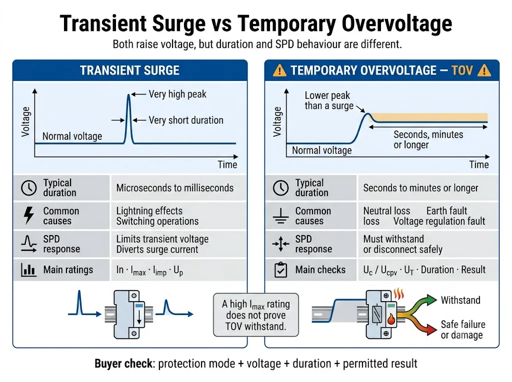
Une surtension est un événement transitoire court que doit limiter un SPD. Un TOV est une tension de puissance alternative ou continue anormale qui demeure suffisamment longtemps pour créer un stress électrique et thermique soutenu.[1][2][4]
La tenue au TOV n'est pas un chiffre de tension unique. Une déclaration significative doit identifier le mode de protection, la tension appliquée, la durée et le résultat attendu.
- Uc ou Ucpv couvre la tension continue. La tension d'exploitation réelle doit rester dans les limites de la cote déclarée.
- UT décrit une condition anormale définie. Elle doit être lue conjointement avec la durée et le résultat du test.
- Un Uc faible peut augmenter la sensibilité au TOV. Une conduction MOV soutenue peut provoquer un échauffement et une déconnexion.
- Un Imax élevé ne prouve pas la résistance au TOV. Les risques de courant d'impulsion et de tension soutenue sont différents.
Décision d'approbation rapide pour les acheteurs
Utilisez ce tableau avant d'approuver un échantillon, un élément de la nomenclature ou un modèle de marque privée. C'est un outil de dépistage, pas un substitut à l'ingénierie de projet.
| Décision | Constatation | Action requise |
|---|---|---|
| Approuver | Les données du modèle exact correspondent à la tension du système, au mode de protection, aux conditions de TOV et aux exigences de court-circuit. | Procéder à l'approbation de l'échantillon ou de la nomenclature, sous réserve de l'examen complet du projet. |
| Retenir | L'UT est indiqué sans durée, le résultat de défaillance sécuritaire n'est pas clair, ou le champ d'application du certificat n'identifie pas le modèle exact. | Demander les conditions de test manquantes, le champ d'application et les informations d'installation. |
| Rejeter | La tension maximale normale dépasse Uc ou Ucpv, le type d'application est incorrect, ou le mode de protection requis n'est pas pris en charge. | Sélectionner un autre modèle ou corriger la spécification du système avant de commander. |
Un produit ne devrait pas être approuvé simplement sur la base d'une étiquette avant, d'une valeur Imax ou d'une déclaration générale de “résistance au TOV”.
- TOV ou surtension transitoire
- Comment lire une caractéristique TOV
- Uc, Ucpv et UT
- Pourquoi une TOV endommage un parafoudre
- Différences entre les modes de protection
- Risques liés à la distribution CA
- Exemple de fiche technique
- Limites en CC et photovoltaïque
- Processus de vérification OEM
- Contrôles après un événement TOV
- FAQ acheteurs
TOV et surtension sont des événements électriques différents
Les deux événements élèvent la tension au-dessus de son niveau normal. Les différences importantes concernent la durée, la source d’énergie et la manière dont le parafoudre réagit.
| Comparaison | Surtension transitoire | Surtension temporaire |
|---|---|---|
| Nature | Une brève impulsion de tension ou de courant présentant un pic élevé. | Une tension efficace CA ou une tension CC anormale qui reste présente. |
| Causes possibles | Effets de la foudre, commutations et interruption de charges inductives. | Perte du neutre, défauts à la terre, mauvaise régulation, tension d’alimentation incorrecte ou défauts de la source. |
| Fonction du SPD | Limite la tension transitoire et dérive le courant d’impulsion. | Doit rester stable ou entrer dans la condition déclarée de fin de vie contrôlée. |
| Caractéristiques nominales principales | In, Imax, Iimp et Up. | Uc ou Ucpv, UT, mode de protection, durée et résultat. |
| Principal risque | Énergie d’impulsion excessive ou contraintes cumulées dues aux surtensions. | Conduction continue, échauffement, emballement thermique ou maintien du courant de défaut. |
La norme applicable et la documentation du produit déterminent la durée exacte de l’essai de TOV. N’appliquez pas un seuil de durée universel à tous les systèmes ou SPD.
Quatre champs sont nécessaires pour comprendre un classement TOV
Des mentions telles que “ résistance élevée aux TOV ” ou “ SPD résistant aux TOV ” ne constituent pas des données d’ingénierie complètes. Les acheteurs ont besoin de quatre champs spécifiques.
| Champ requis | Ce que cela signifie | Impact sur l’approvisionnement |
|---|---|---|
| Mode de protection | Les deux conducteurs entre lesquels la tension anormale est appliquée. | Les chemins L-N, L-PE et N-PE peuvent être soumis à des tensions de défaut différentes. |
| Tension appliquée | La tension d’essai TOV spécifiée en valeur efficace CA ou en CC, souvent identifiée comme UT. | Comparez-la à la tension anormale plausible dans le système réel. |
| Durée | Durée pendant laquelle la tension anormale est appliquée dans les conditions indiquées. | Un SPD peut supporter une tension pendant une courte durée, mais se déconnecter lors d’une exposition plus longue. |
| Résultat | Le comportement requis après ou pendant l’essai. | Déterminer si le SPD reste fonctionnel, se déconnecte ou doit être remplacé. |
Uc, Ucpv et UT ne signifient pas la même chose
Uc est la tension maximale de fonctionnement continu pouvant être appliquée en permanence au mode de protection indiqué du SPD. Ucpv est le paramètre correspondant utilisé pour les SPD photovoltaïques.[1][2][6]
UT décrit le comportement lors d’une condition spécifiée de tension temporairement anormale. Uc ou Ucpv et UT sont liés, mais l’un ne peut pas remplacer l’autre.
| Paramètres | Question traitée | Risque d'approbation |
|---|---|---|
| Un ou Uo | Quelle est la tension nominale du système ou la tension phase-neutre ? | Il s'agit d'un point de départ, et non de la valeur finale de sélection de tension SPD. |
| Uc | Le SPD peut-il rester connecté en permanence à cette tension ? | Une valeur trop faible peut entraîner une augmentation des fuites, un échauffement et une coupure prématurée. |
| Ucpv | Le SPD photovoltaïque peut-il rester connecté à la tension maximale calculée du générateur ? | La tension de fonctionnement normale de l'onduleur ne suffit pas à elle seule. |
| UT | Que se passe-t-il lorsque la tension et la durée indiquées sortent de la norme ? | Une valeur de tension sans indication de durée ni de résultat est incomplète. |
| Haut de la page | Quel est le niveau de protection contre les surtensions indiqué lors de l'essai de surtension spécifié ? | Une valeur Uc plus élevée ne garantit pas automatiquement la coordination de protection la plus adaptée. |
Pourquoi une valeur Uc faible peut-elle entraîner une défaillance ?
La plupart des dispositifs de protection contre les surtensions (SPD) à courant alternatif limitant la tension utilisent une ou plusieurs varistances à oxyde métallique (MOV). Sous une tension normale, une MOV ne laisse passer qu'un faible courant de fuite.
Lorsque la tension appliquée dépasse la plage de fonctionnement stable du composant, le courant traversant le MOV peut augmenter brusquement. Si cette tension anormale persiste, l'énergie électrique est convertie en chaleur au lieu d'être dissipée sous la forme d'une seule impulsion de surtension.[9]
Un Uc plus élevé est-il toujours préférable ?
Non. Une valeur Uc plus élevée peut augmenter la marge de tension continue, mais le SPD choisi doit tout de même offrir une valeur Up adaptée, un mode de protection approprié et une coordination adéquate avec l'équipement à protéger.
Le choix approprié ne se résume pas simplement à la valeur Uc la plus élevée disponible. Il s’agit d’une valeur nominale qui couvre en toute sécurité la tension de service maximale réelle et les conditions de défaut plausibles, tout en répondant au niveau de protection requis.[3]
Comment un TOV peut-il faire chauffer, déconnecter ou endommager un SPD ?
La réponse exacte dépend de la technologie SPD, de la conception interne et du type de défaillance du système. Une séquence de défaillance courante basée sur un MOV est illustrée ci-dessous.
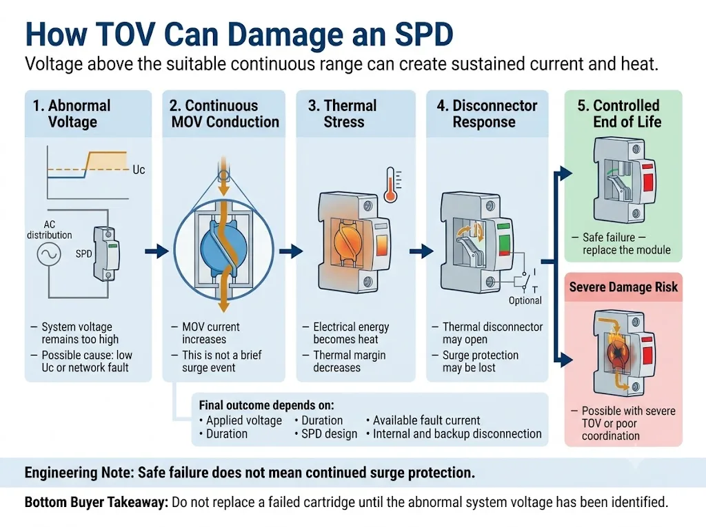
- La tension appliquée dépasse la plage continue admissible. Cela peut être dû à un choix de valeur Uc trop faible ou à un dysfonctionnement du système.
- Le composant de limitation de tension est conducteur en permanence. Le SPD consomme du courant à fréquence industrielle ou continu au lieu de gérer une seule impulsion brève.
- La température interne augmente. Un apport énergétique continu réduit la marge thermique restante.
- Le sectionneur thermique risque de s'ouvrir. Une déconnexion contrôlée permet d'isoler le composant sollicité et de modifier l'indicateur d'état.
- Des dégâts importants restent possibles. Une surtension de ligne (TOV) importante, un courant de défaut élevé ou une coupure insuffisante peuvent aggraver la panne.
Des recherches sur les TOV menées par le NIST ont montré que les réactions aux SPD soumis à une tension anormale prolongée peuvent aller de l'absence totale de dommage à la destruction complète. L'article identifie la tension de fonctionnement continue maximale et la réponse du sectionneur comme des facteurs importants de la vulnérabilité aux TOV.[9]
Le TOV doit être vérifié pour chaque mode de protection
Un SPD multipolaire n'est pas soumis à une seule et même tension. Chaque élément de protection détecte la tension entre les deux conducteurs raccordés à ce circuit de protection.
| Mode de protection | Question de sélection classique | Risque TOV à confirmer |
|---|---|---|
| L-N | Quelle est la tension maximale continue entre phase et neutre ? | Perte du neutre, mauvaise connexion du neutre et déséquilibre de charge. |
| L-PE | Quelle tension peut apparaître entre le conducteur de phase et la terre ? | Défauts à la terre, déplacement du neutre et comportement du système de mise à la terre. |
| N-PE | Quelle technologie de protection N-PE et quel niveau de protection sont utilisés ? | Tension temporaire entre le neutre et la terre dans certaines conditions de défaut à la terre. |
| CC +/− | Quelle est la tension continue maximale entre les pôles ? | Tension de charge, défauts de régulation et configuration incorrecte du circuit. |
| Pôle CC-PE | Comment le système à courant continu est-il mis à la terre ? | Un défaut à la terre peut entraîner un décalage de tension sur un chemin de protection pôle-terre. |
Pourquoi la perte de neutre est-elle un scénario TOV AC critique ?
Dans un système triphasé à quatre fils sain de 230/400 V, un chemin de protection L-N est normalement soumis à environ 230 V.
Si le conducteur neutre se rompt ou présente une impédance élevée, le point neutre n'est plus stable. En présence de charges monophasées déséquilibrées, certaines tensions L-N peuvent chuter tandis que d'autres augmentent considérablement et peuvent approcher la tension entre phases de 400 V.[4][9]
État de bonne santé par rapport à un état neutre ou de perte
Un SPD de 275 V Uc peut convenir à un circuit L-N stable de 230 V lorsque l'ensemble des exigences relatives au système et au produit sont respectées.
Si une perte sur le neutre entraîne une tension continue nettement plus élevée sur le même circuit de protection, le parafoudre peut commencer à conduire en continu. Pour savoir s'il résiste, s'il se déconnecte en toute sécurité ou s'il subit des dommages, il faut se référer aux données TOV du modèle concerné.
Cet exemple ne prouve pas que chaque événement de perte au neutre génère exactement 400 V. La tension réelle dépend des charges raccordées, de la configuration du réseau et des conditions du défaut.
Défauts à la terre et dispositif de mise à la terre
Les systèmes TN-S, TN-C-S, TT et IT peuvent générer des tensions temporaires variables sur les voies de protection L-N, L-PE et N-PE. L'intensité réelle dépend de la configuration de l'installation et des conditions du défaut.[3][4]
Cela revêt une importance particulière lorsqu'on compare les circuits de type 4+0 et 3+1. Les modules L-N et l'élément N-PE remplissent des fonctions différentes et il ne faut pas supposer qu'ils présentent un comportement TOV identique.
Générateurs, transformateurs et réseaux instables
Les défauts de régulation des générateurs, les erreurs de prise de transformateur, le rejet de charge, la ferrorésonance et une mauvaise régulation du réseau peuvent entraîner une tension anormale prolongée.
Pour ces projets, demandez les relevés de tension mesurés ou la tolérance de tension prévue. La tension nominale à elle seule ne suffit pas pour l'homologation définitive de Uc.
Les exigences relatives à l'installation et les conditions TOV spécifiques au système doivent être vérifiées par rapport à l'édition applicable de la norme CEI 60364 et au code électrique local. Les éléments connexes Guide d'installation des SPD selon la norme CEI 60364-5-534 explique les vérifications générales liées à l'installation.
Comment lire une entrée de fiche technique TOV réelle
L'exemple suivant utilise des valeurs publiées dans le guide technique d'un fabricant tiers. Il explique uniquement la méthode de lecture. Il ne s'agit pas d'une recommandation concernant un modèle LEEYEE et ces informations ne doivent pas être transposées à un autre produit sans vérification préalable.[10]
| Article publié | Interprétation correcte | Une hypothèse erronée à éviter |
|---|---|---|
| Uc 275 V | La tension maximale de fonctionnement continu déclarée pour le mode de protection indiqué. | Le produit peut fonctionner en continu à n'importe quelle tension inférieure à sa valeur UT maximale. |
| UT 337 V / 5 s | Une condition TOV de courte durée dont les résultats sont indiqués dans la documentation du produit concerné. | 337 V est une autre tension nominale de fonctionnement en continu. |
| UT 442 V / 120 min | Une condition de plus longue durée associée à un résultat déclaré de « défaillance sans danger ». | Le SPD continue d'assurer une protection normale pendant deux heures à 442 V. |
| Valeur N-PE distincte | Une condition TOV spécifiquement définie pour l’élément de protection N-PE. | Cette même valeur s'applique automatiquement aux éléments L-N et L-PE. |
Quels sont les éléments à vérifier sur un modèle LEEYEE ?
Ne partez pas du principe qu'un exemple fourni par un tiers correspond à un produit LEEYEE. Demandez la fiche technique du modèle LEEYEE concerné, le schéma de raccordement ainsi que la portée des essais ou des certificats applicables afin de valider votre projet.
Justificatifs spécifiques au modèle à fournir
- Étiquette exacte du produit et de la cartouche
- Uc ou Ucpv pour le mode de protection indiqué
- Tension UT, durée et résultat annoncé
- Fonctionnement de la fenêtre d'état visuel
- Coordonnées pour la signalisation à distance
- Exigences en matière de déconnexion interne et externe
- Classification Isccr ou ISCPV, le cas échéant
- Exigences relatives aux fusibles de secours ou aux disjoncteurs différentiels
- Instructions d'installation et de câblage
- Portée du rapport ou du certificat spécifique au modèle
- Étiquette OEM et plan d'homologation de l'emballage
- Registre de contrôle et d'homologation des échantillons
Les preuves doivent être examinées au niveau du modèle exact. Un certificat, un rapport ou une fiche technique pour une version de tension ou une configuration de pôle donnée ne doit pas être considéré comme couvrant une autre version.
Les conclusions TOV AC s'appliquent-elles directement aux SPDs DC ou PV ?
Non. Les circuits en courant continu (CC) généraux et les circuits photovoltaïques solaires nécessitent des calculs de tension, des modes de protection et des normes de produits distincts.
La norme CEI 61643-41:2025 concerne les parafoudres raccordés à des circuits d'alimentation basse tension en courant continu généraux. Les parafoudres photovoltaïques relèvent toujours de la norme CEI 61643-31, les principes de sélection étant définis dans la norme CEI 61643-32.[5][6][7]
Utilisez le fichier séparé Guide de sélection Ucpv pour parafoudres CC et PV pour l'ensemble du processus de sélection de la tension des modules photovoltaïques.
Flux de travail de vérification du TOV SPD pour l'approbation OEM
Vérifiez le système électrique avant d'approuver le dispositif de protection contre les surtensions (SPD). Le workflow ci-dessous permet de relier entre elles les données du système, les caractéristiques techniques du produit et les documents d'homologation.
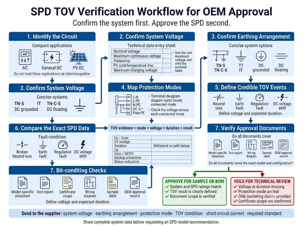
- Identifiez le circuit. Distinguer les applications liées au réseau CA, au courant continu général et à l'énergie solaire photovoltaïque. Le fait que les boîtiers soient similaires ne rend pas les produits interchangeables.
- Vérifiez la tension de fonctionnement maximale réelle. Prendre en compte la tolérance d'alimentation, le comportement du générateur ou du transformateur, la tension de charge ou la tension photovoltaïque à basse température.
- Vérifiez le montage de la mise à la terre. Indiquez TN-S, TN-C-S, TT, IT ou la méthode de mise à la terre en courant continu applicable.
- Répertorier tous les modes de protection. Vérifiez les circuits L-N, L-PE, N-PE, pôle à pôle et pôle à terre, selon le cas.
- Définir les événements TOV crédibles. Passer en revue les pertes au neutre, les défauts à la terre, les défauts de régulation et les anomalies spécifiques à la source.
- Comparez l'ensemble des données SPD. Vérifier les valeurs Uc ou Ucpv, UT, la durée, le résultat, Up, la capacité de court-circuit et le dispositif de coupure.
- Vérifier le champ d'application du document d'approbation. Vérifiez que la fiche technique, le rapport et le certificat correspondent bien à la tension, à la configuration polaire et au modèle commandés.
Informations à fournir avant de demander une recommandation de modèle
- Tension nominale du système
- Tension continue maximale
- Applications CA, CC générale ou photovoltaïques
- Fréquence du système, le cas échéant
- Dispositif de mise à la terre
- Modes de protection requis
- Scénario de perte au neutre ou de défaut à la terre
- Uc ou Ucpv à l'étude
- Tension et durée requises pour le TOV
- Résultat requis en matière de résistance ou de défaillance sans risque
- Courant de court-circuit prospectif
- Informations sur les fusibles de secours ou les disjoncteurs différentiels
- Norme ou certificat requis
- Exigence de signalisation à distance
- Quantité et emplacement de montage
- Exigences relatives à l'étiquette ou à l'emballage OEM
Confirmer les données TOV avant d'approuver le modèle SPD
Indiquez la tension du système, le schéma de mise à la terre, les modes de protection et les conditions de tension anormale avérées. LEEYEE peut vous aider à déterminer quelles données Uc, Ucpv et TOV doivent être vérifiées avant la validation d’un échantillon ou d’une nomenclature.
CNSPD est la plateforme de LEEYEE dédiée à la protection contre les surtensions, destinée aux acheteurs techniques du monde entier. Conçu pour protéger. Fiable pour durer.
Partagez les informations relatives à votre système afin que nous puissions les examinerQue doit-on vérifier après un événement TOV suspecté ?
N'installez pas de cartouche de rechange avant d'avoir identifié la tension anormale d'origine. Un nouveau SPD risque de tomber à nouveau en panne si le défaut du système persiste.
- Mettez le circuit hors tension conformément à la procédure de sécurité électrique en vigueur sur le site.
- Notez l'indicateur SPD, l'alarme à distance et l'étiquette complète du produit.
- Mesurez les tensions entre L-N, L-L, L-PE, N-PE ou la tension aux bornes du pôle CC, selon le cas.
- Vérifiez la continuité du neutre, la mise à la terre et le schéma unifilaire du circuit.
- Vérifiez la cartouche, la base, les conducteurs, les bornes et le dispositif de protection de secours.
- Examiner les dossiers relatifs aux générateurs, aux transformateurs, aux onduleurs, aux relais et aux incidents sur le réseau.
- Vérifiez les données de remplacement Uc, Ucpv et TOV, ainsi que la configuration de la protection.
Pour un processus de diagnostic plus approfondi, utilisez le Guide sur les causes des défaillances du SPD.
Questions fréquentes sur la résistance TOV SPD
Un SPD peut-il protéger un équipement contre une surtension temporaire ?
Un SPD est principalement destiné à limiter les surtensions transitoires. Il ne régule ni n'élimine généralement une tension anormale persistante du réseau. Lors d'une surtension transitoire, il peut rester stable ou entrer dans l'état déclaré de fin de vie contrôlée.
Une montée en tension temporaire (TOV) peut-elle provoquer la combustion d'un parafoudre ?
Oui. Une conduction prolongée peut entraîner un échauffement, un emballement thermique, une déconnexion ou des dommages graves. Le résultat dépend de la tension, de la durée, de la conception du parasurtenseur, du courant de défaut disponible et de la coordination des dispositifs de protection.
Un Imax plus grand améliore-t-il la résistance au TOV ?
Pas nécessairement. L'Imax est un paramètre lié au courant d'impulsion. L'adéquation au TOV dépend de la tension de fonctionnement en continu, du mode de protection, du comportement défini du TOV et de la conception du dispositif de coupure.
Une valeur Uc plus élevée permet-elle d'éviter tous les dysfonctionnements du TOV ?
Non. Une valeur Uc plus élevée peut augmenter la marge de tension continue, mais la durée, le mode de protection, la technologie SPD et le comportement de coupure continuent d'influencer le résultat.
Une perte de neutre peut-elle endommager un parafoudre de 275 V ou 320 V ?
C'est possible. Un décalage du neutre dans un réseau triphasé à quatre fils peut faire grimper la tension aux bornes d'un circuit de protection L-N bien au-delà de la valeur normale. Le résultat dépend de la tension réelle, de la durée et du comportement TOV propre au modèle.
Que signifie « l'échec sans risque » ?
Cela signifie qu’une déconnexion contrôlée ou la fin de vie du module peuvent être autorisées dans les conditions d’essai indiquées. Cela ne signifie pas pour autant que le module continue d’assurer la protection contre les surtensions.
La tension Ucpv correspond-elle à la tension nominale d'une installation photovoltaïque ?
Non. L'Ucpv correspond à la tension de fonctionnement continue maximale déclarée pour le parafoudre photovoltaïque. Elle doit être comparée à la tension maximale calculée pour le parc photovoltaïque et la configuration de protection réels.
Quels documents TOV un acheteur OEM doit-il demander ?
Demandez la fiche technique du modèle précis, le schéma du mode de protection, les valeurs Uc ou Ucpv, la tension UT, la durée, la définition des résultats, la capacité de court-circuit, les exigences en matière de protection de secours, les instructions d'installation et le champ d'application du certificat.
Références
- Commission électrotechnique internationale, CEI 61643-01:2024 — Parafoudres basse tension — Partie 01 : Exigences générales et méthodes d'essai. Page de publication officielle de l'IEC.
- Commission électrotechnique internationale, IEC 61643-11:2025 — Dispositifs de protection contre les surtensions à basse tension — Partie 11 : Dispositifs de protection contre les surtensions raccordés aux réseaux d'alimentation à basse tension en courant alternatif — Exigences et méthodes d'essai. Page de publication officielle de l'IEC.
- Commission électrotechnique internationale, IEC 61643-12:2020 — Dispositifs de protection contre les surtensions à basse tension — Partie 12 : Dispositifs de protection contre les surtensions raccordés aux réseaux d'alimentation à basse tension — Principes de sélection et d'application. Page de publication officielle de l'IEC.
- Commission électrotechnique internationale, IEC 60364-4-44:2024 — Installations électriques à basse tension — Partie 4-44 : Protection pour la sécurité — Protection contre les perturbations de tension et les perturbations électromagnétiques. Page de publication officielle de l'IEC.
- Commission électrotechnique internationale, IEC 61643-41:2025 — Dispositifs de protection contre les surtensions à basse tension — Partie 41 : Dispositifs de protection contre les surtensions raccordés à des réseaux d'alimentation à basse tension en courant continu — Exigences et méthodes d'essai. Page de publication officielle de l'IEC.
- Commission électrotechnique internationale, IEC 61643-31:2018 et rectificatif 1:2022 — Exigences et méthodes d'essai applicables aux dispositifs de protection contre les surtensions (SPD) destinés aux installations photovoltaïques. Page de publication officielle de l'IEC.
- Commission électrotechnique internationale, IEC 61643-32:2017 et rectificatif 1:2019 — Dispositifs de protection contre les surtensions raccordés au côté courant continu des installations photovoltaïques — Principes de sélection et d'application. Page de publication officielle de l'IEC.
- Commission électrotechnique internationale, IEC 60364-7-712:2025 — Installations électriques à basse tension — Installations d'alimentation en énergie solaire photovoltaïque. Page de publication officielle de l'IEC.
- D. Kladar, F. Martzloff et D. Nastasi, Effets des TOV sur les dispositifs de protection contre les surtensions, Eaton Electrical et EPRI Solutions, sous l'égide de l'Institut national américain des normes et des technologies (NIST). Document technique hébergé par le NIST.
- ABB Furse, Guide des produits de la série de protection contre les surtensions ESP de type 1 et de type 2, y compris les données spécifiques à chaque modèle concernant les valeurs Uc, UT, la résistance et les conditions de défaillance sans risque. Guide technique officiel d'ABB.
