
Un SPD può sopravvivere a un impulso di fulmine molto alto ma guastarsi durante una tensione molto più bassa che rimane per secondi o più a lungo. Questa tensione anomala più lunga è chiamata sovratensione temporanea, o TOV.
Per gli acquirenti OEM e i costruttori di pannelli, la resistenza TOV è un parametro di rischio di approvvigionamento. Aiuta a determinare se un SPD può rimanere stabile, disconnettersi in modo controllato o subire danni gravi quando la tensione di sistema supera il range operativo continuo previsto.
Indice dei contenuti
Cosa significa la resistenza TOV SPD?
Un sovratensione è un evento transitorio breve che un SPD è progettato per limitare. Un TOV è una tensione anomala a frequenza di rete o in CC che rimane abbastanza a lungo da creare stress elettrico e termico sostenuto.[1][2][4]
La resistenza al TOV non è un valore di tensione autonomo. Una dichiarazione significativa deve identificare la modalità di protezione, la tensione applicata, la durata e il risultato atteso.
- Uc o Ucpv copre la tensione continua. La tensione operativa reale deve rimanere entro i limiti dichiarati.
- UT descrive una condizione anomala definita. Deve essere letto insieme alla durata e al risultato del test.
- Una bassa Uc può aumentare la sensibilità al TOV. La conduzione sostenuta di MOV può causare riscaldamento e disconnessione.
- Un alto Imax non prova la resistenza al TOV. I rischi da corrente d'impulso e tensioni sostenute sono diversi.
Decisione di approvazione rapida per gli acquirenti
Utilizzare questa tabella prima di approvare un campione, un articolo BOM o un modello a marchio privato. È uno strumento di screening, non un sostituto per l'ingegneria di progetto.
| Decisione | Risultato | Azione richiesta |
|---|---|---|
| Approva | I dati esatti del modello corrispondono alla tensione del sistema, alla modalità di protezione, alle condizioni TOV e ai requisiti di cortocircuito. | Procedere all'approvazione del campione o della distinta base, soggetta alla completa revisione del progetto. |
| Tieni | L'UT è mostrato senza durata, il risultato di sicurezza è poco chiaro, o il campo di applicazione del certificato non identifica il modello esatto. | Richiedi la condizione di prova mancante, il campo di rapporto e le informazioni di installazione. |
| Rifiuta | La tensione massima normale supera Uc o Ucpv, il tipo di applicazione è errato, o la modalità di protezione richiesta non è supportata. | Seleziona un altro modello o correggi le specifiche del sistema prima di ordinare. |
Un prodotto non dovrebbe essere approvato solo in base a un'etichetta frontale, al valore di Imax o a una generica affermazione di “resistenza TOV”.
- TOV rispetto alle sovratensioni
- Come leggere una classificazione TOV
- Uc, Ucpv e UT
- Perché la TOV danneggia un SPD
- Differenze nelle modalità di protezione
- Rischi di distribuzione CA
- Esempio di scheda tecnica
- Confine CC e FV
- Flusso di lavoro di verifica OEM
- Controlli dopo un evento TOV
- FAQ per l'acquirente
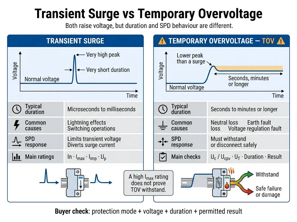
TOV e Surge sono eventi elettrici diversi
Entrambi gli eventi innalzano la tensione al di sopra del suo livello normale. Le differenze importanti riguardano la durata, la fonte di energia e la modalità di risposta dell'SPD.
| Confronto | Sovratensione transitoria | Sovratensione temporanea |
|---|---|---|
| Natura | Un breve impulso di tensione o corrente con un picco elevato. | Una tensione anomala in corrente alternata (RMS) o continua che rimane presente. |
| Possibili cause | Effetti dei fulmini, commutazione e interruzione di carichi induttivi. | Perdita del neutro, guasti a terra, scarsa regolazione, tensione di alimentazione errata o guasti alla sorgente. |
| Funzione SPD | Limita la tensione transitoria e devia la corrente d'impulso. | Deve rimanere stabile o entrare nella condizione dichiarata di fine vita controllata. |
| Valori nominali principali | In, Imax, Iimp e Up. | Uc o Ucpv, UT, modalità di protezione, durata e risultato. |
| Rischio principale | Energia impulsiva eccessiva o stress da sovratensione accumulato. | Conduzione continua, riscaldamento, fuga termica o corrente susseguente di guasto. |
La norma applicabile e la documentazione del prodotto determinano l'esatta durata del test TOV. Non applicare una soglia temporale universale a ogni sistema o SPD.
Sono necessari quattro campi per comprendere una valutazione TOV
Affermazioni come “elevata resistenza TOV” o “SPD a prova di TOV” non costituiscono dati tecnici completi. Gli acquirenti necessitano di quattro campi specifici.
| Campo obbligatorio | Cosa significa | Impatto sull'approvvigionamento |
|---|---|---|
| Modalità di protezione | I due conduttori tra i quali viene applicata la tensione anomala. | I percorsi L-N, L-PE e N-PE possono essere soggetti a diverse tensioni di guasto. |
| Tensione applicata | La tensione di prova TOV in CA RMS o CC specificata, spesso identificata come UT. | Confrontarlo con la tensione anomala attendibile nel sistema reale. |
| Durata | Quanto a lungo viene applicata la tensione anomala durante la condizione dichiarata. | Un SPD può resistere brevemente a una tensione, ma disconnettersi durante un'esposizione più prolungata. |
| Risultato | Il comportamento richiesto dopo o durante il test. | Determinare se l'SPD rimane funzionale, si scollega o richiede la sostituzione. |
Uc, Ucpv e UT non significano la stessa cosa
Uc è la tensione massima di esercizio continuo che può essere applicata in modo continuativo alla modalità di protezione SPD indicata. Ucpv è il parametro corrispondente utilizzato per gli SPD fotovoltaici.[1][2][6]
UT descrive il comportamento durante una specifica condizione di tensione anomala temporanea. Uc o Ucpv e UT sono correlati, ma non possono sostituirsi a vicenda.
| Parametro | Domanda risolta | Rischio di approvazione |
|---|---|---|
| Un o Uo | Qual è la tensione nominale del sistema o fase-neutro? | Si tratta di un punto di partenza, non del valore finale di selezione della tensione dell'SPD. |
| Uc | L'SPD può rimanere collegato in modo continuo a questa tensione? | Un valore troppo basso può aumentare le perdite, il riscaldamento e la disconnessione prematura. |
| Ucpv | Il dispositivo di protezione da sovratensioni (SPD) fotovoltaico può rimanere collegato alla tensione massima calcolata dell'array? | La sola tensione operativa normale dell'inverter non è sufficiente. |
| UT | Cosa succede in presenza della tensione e della durata anomale indicate? | Un valore di tensione privo di durata e risultato è incompleto. |
| Su | Quale livello di protezione dalla tensione viene dichiarato durante il test di sovratensione specificato? | Un valore Uc più elevato non garantisce automaticamente il coordinamento della protezione più idoneo. |
Perché un valore Uc basso può causare un guasto?
La maggior parte degli SPD per corrente alternata a limitazione di tensione utilizza uno o più varistori a ossido metallico. In condizioni di tensione normale, un MOV trasporta solo una piccola corrente di dispersione.
Quando la tensione applicata supera l'intervallo operativo stabile del componente, la corrente del MOV può aumentare bruscamente. Se la tensione anomala persiste, l'energia elettrica viene convertita in calore anziché essere gestita come un singolo impulso di sovratensione.[9]
Un valore Uc più elevato è sempre preferibile?
No. Un valore Uc più alto può aumentare il margine di tensione continua, ma l'SPD selezionato deve comunque garantire un valore Up adeguato, una modalità di protezione corretta e il coordinamento con l'apparecchiatura da proteggere.
La scelta corretta non è semplicemente il valore Uc più alto disponibile. Si tratta di una classificazione che copre in sicurezza la tensione operativa massima reale e le condizioni di guasto plausibili, soddisfacendo al contempo il livello di protezione richiesto.[3]
Come può il TOV far surriscaldare un SPD, disconnetterlo o bruciarlo?
La risposta esatta dipende dalla tecnologia dell'SPD, dalla costruzione interna e dal guasto del sistema. Di seguito viene mostrata una comune sequenza di guasto basata su MOV.
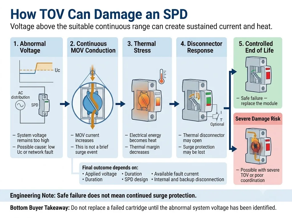
- La tensione applicata supera l'intervallo continuo idoneo. Ciò può derivare da una selezione di Uc troppo bassa o da una condizione anomala del sistema.
- Il componente di limitazione della tensione conduce in modo continuo. L'SPD sta assorbendo corrente a frequenza industriale o continua invece di gestire un singolo impulso breve.
- La temperatura interna aumenta. Un apporto energetico continuo riduce il margine termico residuo.
- Il disconnettore termico potrebbe aprirsi. Una disconnessione controllata può isolare il componente sotto sforzo e modificare l'indicatore di stato.
- Permane la possibilità di danni gravi. Una sovratensione temporanea (TOV) severa, un'elevata corrente di guasto disponibile o una disconnessione inadeguata possono amplificare il guasto.
La ricerca sulle TOV condotta dal NIST ha rilevato che le risposte degli SPD in condizioni di tensione anomala prolungata possono variare dall'assenza di danni alla distruzione totale. Il documento identifica la tensione massima di funzionamento continuo e la risposta del disconnettore come fattori determinanti nella suscettibilità alle TOV.[9]
Il TOV deve essere controllato per ciascuna modalità di protezione
Un SPD multipolare non è esposto a una singola tensione. Ogni elemento di protezione rileva la tensione tra i due conduttori collegati a quel percorso di protezione.
| Modalità di protezione | Domanda di selezione standard | Rischio TOV da confermare |
|---|---|---|
| L-N | Qual è la tensione massima continua fase-neutro? | Perdita del neutro, connessione del neutro scadente e squilibrio del carico. |
| L-PE | Quale tensione può manifestarsi tra il conduttore di fase e la terra? | Guasti a terra, spostamento del neutro e comportamento del sistema di messa a terra. |
| N-PE | Quale tecnologia di protezione N-PE e quale valore nominale vengono utilizzati? | Tensione temporanea neutro-terra durante determinate condizioni di guasto a terra. |
| CC +/− | Qual è la tensione massima in corrente continua tra i poli? | Tensione di carica, guasti di regolazione e configurazione errata del circuito. |
| Polo CC-PE | In che modo il sistema in corrente continua è riferito a terra? | Un guasto a terra può causare uno spostamento di tensione lungo il percorso di protezione tra polo e terra. |
Perché la perdita di neutro è uno scenario critico TOV AC
In un sistema trifase a quattro fili da 230/400 V in condizioni normali, un percorso di protezione L-N rileva solitamente circa 230 V.
Se il conduttore di neutro si interrompe o sviluppa un'impedenza elevata, il punto neutro non è più stabile. Con carichi monofase sbilanciati, alcune tensioni L-N possono diminuire mentre altre aumentano considerevolmente, potendo avvicinarsi alla tensione concatenata di 400 V.[4][9]
Alimentazione sana rispetto alla condizione di perdita del neutro
Un SPD da 275 V Uc può essere idoneo per un circuito stabile da 230 V L-N quando sono soddisfatti i requisiti completi del sistema e del prodotto.
Se la perdita del neutro causa nel medesimo percorso di protezione una tensione sostenuta molto più elevata, l'SPD potrebbe iniziare a condurre in modo continuo. La capacità di resistere, di disconnettersi in sicurezza o l'eventuale danneggiamento devono essere verificati in base ai dati TOV dello specifico modello.
Questo esempio non dimostra che ogni evento di perdita del neutro produca esattamente 400 V. La tensione effettiva dipende dai carichi collegati, dalla configurazione della rete e dalla condizione di guasto.
Guasti a terra e sistema di messa a terra
I sistemi TN-S, TN-C-S, TT e IT possono generare diverse tensioni temporanee sui percorsi di protezione L-N, L-PE e N-PE. Lo stress effettivo dipende dalla configurazione dell'impianto e dalla condizione di guasto.[3][4]
Ciò è particolarmente importante quando si confrontano circuiti 4+0 e 3+1. I moduli L-N e l'elemento N-PE svolgono funzioni diverse e non si deve presumere che abbiano un comportamento TOV identico.
Generatori, trasformatori e reti instabili
Guasti alla regolazione del generatore, errori nei commutatori sotto carico dei trasformatori, distacco del carico, ferro-risonanza e una scarsa regolazione da parte dell'ente fornitore possono generare tensioni anomale prolungate.
Per questi progetti, richiedere i registri delle tensioni misurate o la tolleranza di tensione di progetto. La sola tensione nominale non è sufficiente per l'approvazione finale di Uc.
I requisiti a livello di installazione e le condizioni TOV specifiche del sistema devono essere verificati in conformità con l'edizione applicabile della norma IEC 60364 e con le normative elettriche locali. La relativa guida all'installazione degli SPD IEC 60364-5-534 illustra i controlli di installazione più ampi.
Come leggere l'ingresso di un datasheet TOV reale
Il seguente esempio utilizza valori pubblicati nella guida tecnica di un produttore terzo. Esso illustra esclusivamente il metodo di lettura. Non costituisce una raccomandazione per un modello LEEYEE e non deve essere applicato a un altro prodotto senza previa verifica.[10]
| Voce pubblicata | Interpretazione corretta | Presunzione errata da evitare |
|---|---|---|
| Uc 275 V | La tensione massima di esercizio continuo dichiarata per la modalità di protezione indicata. | Il prodotto può funzionare in modo continuo a qualsiasi tensione inferiore al suo valore UT massimo. |
| UT 337 V / 5 s | Una condizione di TOV di breve durata con l'esito indicato nella medesima documentazione del prodotto. | 337 V è un'ulteriore tensione operativa continua nominale. |
| UT 442 V / 120 min | Una condizione di durata maggiore associata a un risultato di guasto sicuro dichiarato. | L'SPD continua a proteggere normalmente per due ore a 442 V. |
| Valore N-PE separato | Una condizione TOV specificamente indicata per l'elemento di protezione N-PE. | Lo stesso valore si applica automaticamente agli elementi L-N e L-PE. |
Cosa verificare su un modello LEEYEE?
Non dare per scontato che un esempio di terze parti rappresenti un prodotto LEEYEE. Richiedere la scheda tecnica esatta del modello LEEYEE, lo schema di collegamento e l'ambito di prova o certificazione applicabile per la conferma del progetto.
Prove specifiche per il modello da richiedere
- Etichetta esatta del prodotto e della cartuccia
- Uc o Ucpv per la modalità di protezione indicata
- Tensione UT, durata e risultato dichiarato
- Funzionamento della finestra di stato visiva
- Informazioni sul contatto di segnalazione remota
- Requisiti di disconnessione interna ed esterna
- Classificazione ISCCR o ISCPV ove applicabile
- Requisiti per fusibile di riserva o interruttore magnetotermico (MCB)
- Istruzioni per l'installazione e il cablaggio
- Ambito del certificato o del rapporto specifico per il modello
- Disegno di approvazione per etichetta e imballaggio OEM
- Verbale di ispezione e approvazione del campione
Le prove devono essere esaminate a livello di modello specifico. Un certificato, un rapporto o una scheda tecnica relativi a una versione di tensione o a una configurazione di poli non devono essere considerati validi per altre versioni.
Le conclusioni TOV AC si applicano direttamente agli SPD DC o PV?
No. I circuiti generali in corrente continua e quelli fotovoltaici richiedono calcoli di tensione, modalità di protezione e standard di prodotto distinti.
La norma IEC 61643-41:2025 riguarda gli SPD collegati a circuiti di alimentazione generali in bassa tensione a corrente continua. Gli SPD per impianti fotovoltaici restano disciplinati dalla norma IEC 61643-31, con i principi di selezione trattati nella norma IEC 61643-32.[5][6][7]
Utilizzare la guida alla selezione separata Guida alla selezione della Ucpv per SPD CC e FV per il processo completo di selezione della tensione FV.
Flusso di lavoro di verifica TOV SPD per approvazione OEM
Verificare l'impianto elettrico prima di approvare l'SPD. Il flusso di lavoro sottostante mantiene collegati i dati di sistema, le specifiche del prodotto e i documenti di approvazione.
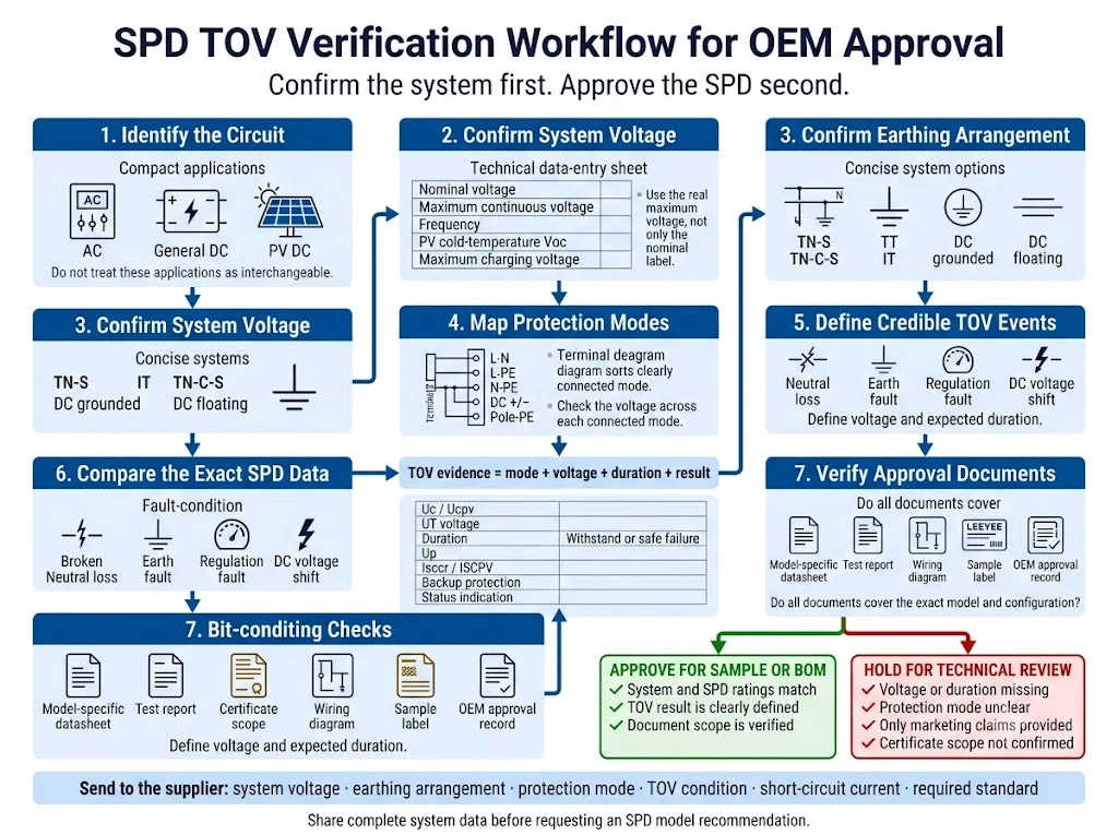
- Identificare il circuito. Separare le applicazioni di rete CA, CC generale e fotovoltaico solare. Involucri simili non rendono i prodotti intercambiabili.
- Verificare la tensione operativa massima effettiva. Includere la tolleranza di alimentazione, il comportamento del generatore o del trasformatore, la tensione di carica o la tensione a bassa temperatura del fotovoltaico.
- Verificare il sistema di messa a terra. Registrare TN-S, TN-C-S, TT, IT o il metodo di messa a terra CC pertinente.
- Mappare ogni modalità di protezione. Verificare i percorsi L-N, L-PE, N-PE, polo-polo e polo-terra come applicabile.
- Definire eventi TOV credibili. Esaminare la perdita del neutro, i guasti a terra, i guasti di regolazione e le condizioni anomale specifiche della sorgente.
- Confrontare i dati SPD completi. Esaminare Uc o Ucpv, UT, durata, risultato, Up, corrente di cortocircuito e schema di disconnessione.
- Verificare l'ambito del documento di approvazione. Confermare che la scheda tecnica, il rapporto e il certificato corrispondano esattamente alla versione di tensione, alla configurazione dei poli e al modello ordinati.
Informazioni da inviare prima di richiedere una raccomandazione sul modello
- Tensione nominale del sistema
- Tensione continua massima
- Applicazione CA, CC generale o FV
- Frequenza di sistema ove applicabile
- Configurazione di messa a terra
- Modalità di protezione richieste
- Scenario di perdita del neutro o guasto a terra
- Uc o Ucpv in fase di valutazione
- Tensione e durata TOV richieste
- Risultato richiesto di tenuta o di guasto sicuro
- Corrente di cortocircuito presunta
- Informazioni sul fusibile di backup o sull'interruttore magnetotermico (MCB)
- Standard o certificato richiesto
- Requisito di segnalazione remota
- Quantità e posizione di installazione
- Requisiti per etichettatura o imballaggio OEM
Confermare i dati TOV prima di approvare il modello SPD
Inviare la tensione di sistema, la disposizione della messa a terra, le modalità di protezione e le condizioni di tensione anomala attendibili. LEEYEE può aiutare a identificare quali dati Uc, Ucpv e TOV debbano essere verificati prima dell'approvazione del campione o della distinta base (BOM).
CNSPD è la piattaforma di LEEYEE dedicata alla protezione dalle sovratensioni per gli acquirenti tecnici globali. Costruiti per Proteggere. Affidabili nel Tempo.
Condividi i dettagli del tuo sistema per una revisioneCosa deve essere controllato dopo un evento TOV sospetto?
Non installare una cartuccia sostitutiva prima di aver identificato la tensione anomala originale. Un nuovo SPD potrebbe guastarsi nuovamente se il guasto al sistema persiste.
- Isolare il circuito in conformità con la procedura di sicurezza elettrica del sito.
- Registrare l'indicatore SPD, l'allarme remoto e l'etichetta completa del prodotto.
- Misurare le tensioni L-N, L-L, L-PE, N-PE o tra i poli CC, a seconda dei casi.
- Verificare la continuità del neutro, la messa a terra e lo schema unifilare corrente.
- Ispezionare la cartuccia, la base, i conduttori, i terminali e la protezione di backup.
- Esaminare i registri di generatori, trasformatori, inverter, relè ed eventi di rete.
- Confermare i dati Uc, Ucpv, TOV di sostituzione e la configurazione della protezione.
Per un processo diagnostico più ampio, consultare la relativa guida alle cause di guasto degli SPD.
Domande frequenti sulla resistenza TOV SPD
Un SPD può proteggere le apparecchiature da una sovratensione temporanea?
Un SPD è destinato principalmente a limitare le sovratensioni transitorie. Normalmente non regola né elimina una tensione di sistema anomala prolungata. Durante una TOV, può rimanere stabile o entrare nella sua condizione dichiarata di fine vita controllata.
Una TOV può causare l'incendio di un SPD?
Sì. Una conduzione prolungata può causare riscaldamento, instabilità termica, disconnessione o danni gravi. Il risultato dipende dalla tensione, dalla durata, dal design dell'SPD, dalla corrente di guasto disponibile e dal coordinamento dei dispositivi di protezione.
Un Imax più elevato migliora la resistenza alle TOV?
Non necessariamente. Imax è un parametro relativo alla corrente impulsiva. L'idoneità alle TOV dipende dalla tensione operativa continua, dalla modalità di protezione, dal comportamento definito per le TOV e dal design del sistema di disconnessione.
Una Uc più alta previene qualsiasi guasto da TOV?
No. Una Uc più elevata può aumentare il margine di tensione continua, ma la durata, la modalità di protezione, la tecnologia dell'SPD e il comportamento di disconnessione influenzano comunque il risultato.
Una perdita del neutro può danneggiare un SPD da 275 V o 320 V?
Sì, può. Lo spostamento del neutro in un sistema trifase a quattro fili può innalzare la tensione lungo il percorso di protezione L-N ben oltre i livelli normali. Il risultato dipende dalla tensione effettiva, dalla durata e dal comportamento TOV specifico del modello.
Cosa si intende per guasto sicuro?
Significa che, nelle condizioni di test dichiarate, può essere consentita una disconnessione controllata o la fine del ciclo di vita. Ciò non implica che il modulo continui a fornire protezione contro le sovratensioni.
Ucpv corrisponde alla tensione nominale di un impianto fotovoltaico?
No. Ucpv è la tensione massima di funzionamento continuo dichiarata per l'SPD fotovoltaico. Deve essere verificata rispetto alla tensione massima calcolata per l'effettivo impianto fotovoltaico e la configurazione di protezione.
Quali documenti relativi alla TOV dovrebbe richiedere un acquirente OEM?
Richiedere la scheda tecnica del modello specifico, lo schema della modalità di protezione, la tensione Uc o Ucpv, la tensione UT, la durata, la definizione del risultato, la corrente di cortocircuito nominale, i requisiti di protezione di backup, le istruzioni di installazione e l'ambito della certificazione.
Riferimenti
- Commissione Elettrotecnica Internazionale, IEC 61643-01:2024 — Dispositivi di protezione contro le sovratensioni a bassa tensione — Parte 01: Requisiti generali e metodi di prova. Pagina ufficiale della pubblicazione IEC.
- Commissione Elettrotecnica Internazionale, IEC 61643-11:2025 — Dispositivi di protezione contro le sovratensioni a bassa tensione — Parte 11: Dispositivi di protezione contro le sovratensioni collegati ai sistemi di alimentazione in bassa tensione a corrente alternata — Requisiti e metodi di prova. Pagina ufficiale della pubblicazione IEC.
- Commissione Elettrotecnica Internazionale, IEC 61643-12:2020 — Dispositivi di protezione contro le sovratensioni a bassa tensione — Parte 12: Dispositivi di protezione contro le sovratensioni collegati ai sistemi di alimentazione in bassa tensione — Principi di selezione e applicazione. Pagina ufficiale della pubblicazione IEC.
- Commissione Elettrotecnica Internazionale, IEC 60364-4-44:2024 — Impianti elettrici a bassa tensione — Parte 4-44: Protezione per la sicurezza — Protezione contro le perturbazioni di tensione e le perturbazioni elettromagnetiche. Pagina ufficiale della pubblicazione IEC.
- Commissione Elettrotecnica Internazionale, IEC 61643-41:2025 — Dispositivi di protezione contro le sovratensioni a bassa tensione — Parte 41: Dispositivi di protezione contro le sovratensioni collegati a sistemi di alimentazione in corrente continua a bassa tensione — Requisiti e metodi di prova. Pagina ufficiale della pubblicazione IEC.
- Commissione Elettrotecnica Internazionale, IEC 61643-31:2018 e Corrigendum 1:2022 — Requisiti e metodi di prova per SPD per impianti fotovoltaici. Pagina ufficiale della pubblicazione IEC.
- Commissione Elettrotecnica Internazionale, IEC 61643-32:2017 e Corrigendum 1:2019 — Dispositivi di protezione contro le sovratensioni collegati al lato in corrente continua degli impianti fotovoltaici — Principi di selezione e applicazione. Pagina ufficiale della pubblicazione IEC.
- Commissione Elettrotecnica Internazionale, IEC 60364-7-712:2025 — Impianti elettrici a bassa tensione — Impianti di alimentazione solare fotovoltaica. Pagina ufficiale della pubblicazione IEC.
- D. Kladar, F. Martzloff e D. Nastasi, Effetti delle sovratensioni a frequenza industriale (TOV) sui dispositivi di protezione contro le sovratensioni, Eaton Electrical ed EPRI Solutions, ospitato dal National Institute of Standards and Technology degli Stati Uniti. documento tecnico ospitato dal NIST.
- ABB Furse, Guida ai prodotti della serie di protezione contro le sovratensioni ESP di tipo 1 e tipo 2, inclusi i dati specifici del modello relativi a Uc, UT, resistenza e guasto sicuro. Guida tecnica ufficiale ABB.
