
Um dispositivo de proteção contra surtos que ficou preto, derreteu, fumou, rachou ou queimou experimentou estresse elétrico ou térmico severo. Os danos visíveis confirmam que um evento sério ocorreu, mas isso não prova por si só se a causa original foi a qualidade do produto, seleção incorreta, fiação, tensão do sistema anormal ou energia de surto além da capacidade do SPD.
Um SPD queimado deve ser tratado como um evento de diagnóstico de sistema. O padrão de queima deve ser revisado juntamente com o rótulo completo do produto, tensão medida, aplicação de AC ou DC, arranjo de aterramento, fiação, proteção a montante e histórico de eventos.
Índice
Por que um SPD queima?
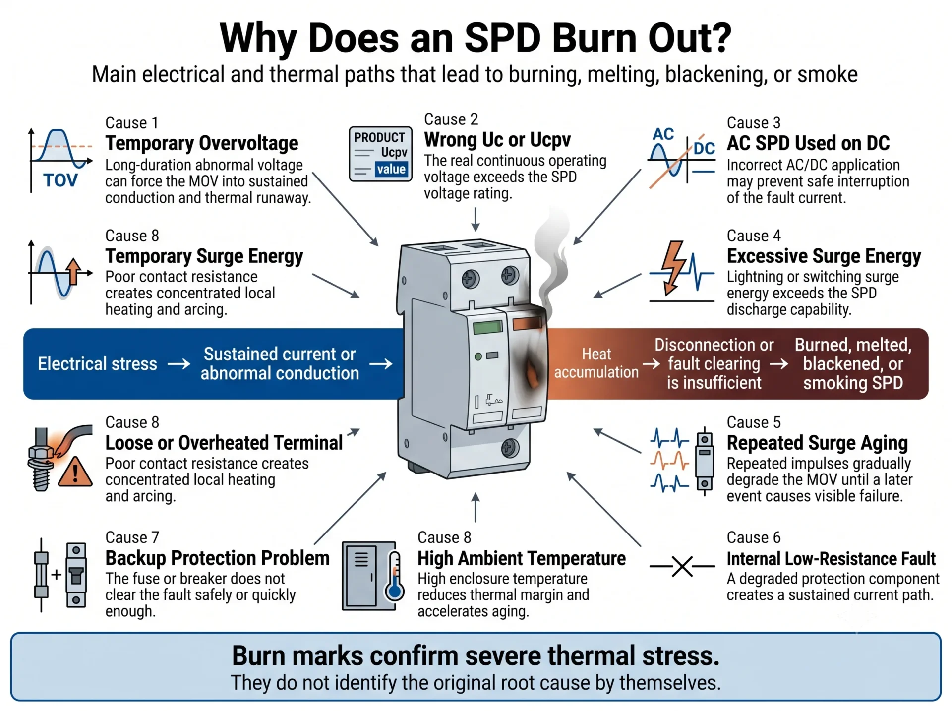
Gatilhos comuns incluem sobrecarga temporária, um Uc ou Ucpv inadequado, uso indevido de CA/CC, energia de surto excessiva, degradação repetida de MOV, terminais soltos, arco local e proteção de backup inadequada.
A queima visível é frequentemente o estágio final de uma sequência. Um evento pode iniciar a falha, enquanto outra condição permite que a temperatura e os danos continuem aumentando.
O que você deve fazer imediatamente após encontrar um SPD queimado?
Um SPD carbonizado, derretido, fumegante ou trincado não deve permanecer energizado. A isolação e a inspeção devem ser realizadas apenas por pessoal qualificado, seguindo os procedimentos de segurança elétrica e bloqueio do local.
- Torne o circuito seguro. Isolar o circuito afetado antes de tocar no SPD, cartucho, terminais ou condutores.
- Não instale imediatamente outro cartucho. Um novo módulo pode falhar novamente se condições de tensão anormal, fiação incorreta ou correntes de falha permanecerem.
- Fotografe a instalação antes da remoção. Capture a frente, os lados, a base, os terminais, condutores, dispositivo a montante e o rótulo completo.
- Preserve o dispositivo com falha. Não descarte ou limpe o cartucho danificado e a base antes da investigação.
- Inspecione todo o ramo de proteção. A causa original pode estar fora do invólucro SPD visível.
Um indicador de status vermelho não é o mesmo que queimadura externa. Uma janela vermelha geralmente indica que um caminho de proteção foi desconectado ou atingiu o fim da vida útil. Carbonização, derretimento ou fumaça indicam um evento mais severo que requer investigação de causa raiz.
Os cinco principais mecanismos por trás do desgaste do SPD
Em vez de tratar cada possível gatilho como uma causa separada, é mais útil entender o mecanismo físico que produziu o calor e o dano.
| Mecanismo de queima | O que geralmente acontece | Evidência típica |
|---|---|---|
| Perda térmica | O MOV desenvolve vazamento aumentado ou condução sustentada, fazendo com que a temperatura e a corrente continuem a subir. | Carbonização interna do cartucho, descoloração, deformação ou dano ao desconector térmico. |
| Aquecimento por conexão local | Uma conexão solta, contaminada ou inadequada cria alta resistência e calor concentrado. | Queima centrada em um terminal, condutor, extremidade ou contato plugável. |
| Corrente de falha sustentada | Um componente de proteção degradado ou caminho de falha permanece conectado tempo suficiente para que a corrente de frequência de potência ou CC amplie o dano. | Cartucho e base derretidos, dano intenso por contato ou carbonização extensa. |
| Arco de CC | Um caminho condutor ou de arco em um circuito de CC não é interrompido de forma segura e continua aquecendo a isolação circundante. | Trilhas de carbono longas, dano severo entre polos ou entre um polo e a terra, especialmente em sistemas fotovoltaicos. |
| Excesso de energia de impulso | Um evento severo ou múltiplos impulsos excedem a capacidade de corrente e energia do SPD. | Ruptura súbita, danos de múltiplos polos ou falha após um evento de relâmpago ou chaveamento registrado. |
Corrida térmica devido a TOV, Uc incorreto ou degradação progressiva do MOV
Um surto transitório normalmente dura por um tempo muito curto. Uma sobretensão temporária pode permanecer por muito mais tempo. Se a tensão em um MOV permanecer acima de um nível contínuo seguro, o MOV pode desenvolver vazamento aumentado, entrar em condução sustentada ou falhar em uma condição de baixa resistência.
À medida que a temperatura aumenta, o comportamento elétrico do MOV pode mudar ainda mais. Isso pode permitir que ainda mais corrente flua, produzindo corrida térmica.
Os gatilhos comuns incluem:
- Perda de neutro ou alta impedância de neutro
- Deslocamento de tensão fase-a-neutro
- Aterramento ou modo de proteção incorretos
- Uc selecionado muito baixo para as condições de operação AC atuais
- Ucpv selecionado muito baixo para a tensão máxima do string PV
- Exposição repetida a surtos e envelhecimento progressivo do MOV
- Anomalias de gerador, transformador, utilidade ou inversor
Um valor alto de Imax não resolve automaticamente um problema de sobretensão sustentada. Imax descreve uma capacidade de corrente de impulso especificada; não substitui a seleção correta de Uc, Ucpv e TOV.
Aquecimento de Conexão Local no Terminal ou Contato de Plugue
Uma conexão de alta resistência pode gerar calor concentrado durante o fluxo normal de corrente ou descarga de surto. O dano mais forte pode permanecer próximo ao terminal do parafuso, entrada do cabo ou contato do cartucho com a base.
Causas possíveis incluem:
- Torque insuficiente ou excessivo no terminal
- Seção transversal do condutor incorreta
- Condutor danificado, solto ou inserido incompletamente
- Bucha ou terminal inadequados
- Fios soltos ou crimpagem ruim
- Pó, umidade, corrosão ou contaminação condutiva
- Contatos de plugue soltos ou superaquecidos
Um terminal queimado não prova que o MOV falhou primeiro. O terminal ou o contato do plugue pode ter iniciado o evento térmico.
Corrente de Falha Sustentada Após o SPD Tornar-se Condutivo ou Curto-Circuito
Os SPDs baseados em MOV geralmente incluem um desconector térmico interno. No entanto, o desconector térmico e a proteção contra sobrecorrente a montante desempenham funções diferentes.
Se uma falha interna severa criar um caminho de baixa resistência, o dano restante depende em parte da corrente de falha disponível e se o arranjo protetivo o isola com segurança.
Os danos podem se tornar mais graves quando:
- A proteção de backup necessária está ausente
- A classificação protetiva a montante excede o valor permitido pelo fabricante
- O fusível ou disjuntor possui capacidade de interrupção insuficiente
- A corrente de curto-circuito prospectiva não foi considerada
- O SPD e a proteção a montante não foram coordenados
- O sistema interno de desconexão térmica não isola o evento conforme pretendido
Não existe um único fusível, disjuntor ou protetor especial universal adequado para cada SPD. O arranjo protetivo correto depende do SPD exato, das instruções do fabricante, do circuito e da corrente de falha disponível.
Arco Sustentado em CC ou Aplicação Incorreta de CA/CC
Um SPD de CA não deve ser instalado em uma string de PV, sistema de bateria ou outro circuito de CC, a menos que o modelo exato esteja explicitamente classificado para essa aplicação de CC e configuração de circuito.
As classificações de CA e CC não podem ser comparadas apenas observando um número de tensão semelhante. O design do circuito interno, o comportamento de desconexão, a disposição dos polos e os requisitos de interrupção de falha podem diferir.
A corrente de CC não passa por pontos naturais de zero de corrente da mesma forma que a corrente de CA. Uma vez que um arco ou caminho condutivo se desenvolva, a interrupção pode, portanto, ser mais difícil.
Nunca substitua um SPD de CC de PV com falha por um SPD de CA apenas porque ambos os rótulos mostram 600 V, 1000 V ou outra tensão aparentemente semelhante. A adequação deve ser confirmada a partir da classificação exata do fabricante e da configuração do circuito.
Energia de surto excedeu a capacidade pretendida do SPD
Um SPD tem capacidade finita de corrente e energia. Um evento severo, impulsos repetidos ou coordenação inadequada entre a proteção Tipo 1 e Tipo 2 podem expor o dispositivo a mais energia do que foi projetado para suportar.
| Parâmetro | O que descreve | Por que isso importa aqui |
|---|---|---|
| Em | Corrente de descarga nominal sob condições de teste especificadas. | Ajuda a descrever a capacidade de impulso repetido do Tipo 2. |
| Imax | Corrente máxima de descarga do Tipo 2 sob condições especificadas. | Um Imax maior não corrige erros de TOV, fiação ou aplicação AC/DC. |
| Iimp | Capacidade de corrente de impulso de relâmpago, normalmente associada ao dever Tipo 1. | Importante onde a corrente parcial de relâmpago pode entrar na instalação. |
| Para cima | Nível de proteção de tensão durante condições especificadas de descarga. | Deve permanecer coordenado com o nível de resistência a impulsos do equipamento protegido. |
Temperatura ambiente alta pode reduzir a margem térmica e acelerar os cinco mecanismos, mas normalmente é uma condição agravante e não uma explicação completa da causa raiz por si só.
Por que o SPD queimou, mas o disjuntor não disparou?
Calor local severo não cria sempre um perfil de corrente que faz o disjuntor a montante desarmar rapidamente.
O disjuntor pode permanecer fechado porque:
- O evento foi um impulso muito curto em vez de uma sobrecorrente sustentada
- Uma falha de alta resistência produziu calor local sem corrente total muito alta
- A corrente permaneceu abaixo do limite de disparo instantâneo do disjuntor
- O caminho de falha não passou pelo dispositivo de proteção esperado
- O disjuntor não estava coordenado com o SPD
- A classificação a montante excedeu o valor de backup permitido pelo fabricante do SPD
- Arco interno ou desconexão criaram um caminho de corrente intermitente complexo
Um dispositivo de proteção inadequado pode disparar por falseamento durante a descarga normal de surto ou não atender aos requisitos de instalação. Verifique as instruções de coordenação do fabricante do SPD, as características do dispositivo de proteção e a corrente de curto-circuito prospectiva.
Um SPD queimado significa que o produto era de baixa qualidade?
Não necessariamente. Um defeito no produto é uma causa possível válida, mas a mesma aparência externa pode ser produzida por voltagem anormal, aplicação incorreta, conexões inadequadas, proteção inadequada ou energia excessiva.
As seguintes constatações ajudam a determinar qual direção de investigação é mais forte.
| Constatação | Mais consistente com um problema do sistema ou da aplicação | Mais consistente com um possível problema do produto |
|---|---|---|
| Diferentes marcas de DPS falham repetidamente na mesma posição de instalação | Forte indicação | Indicação mais fraca |
| A tensão de operação medida excede Uc ou Ucpv | Forte indicação | Não comprova defeito no produto |
| Um DPS CA foi instalado em um circuito CC não aprovado | Indicação muito forte | Indicação fraca |
| O aquecimento concentra-se em um terminal solto ou preparado incorretamente | Forte indicação | Mais fraco, a menos que o projeto do terminal esteja com defeito |
| O mesmo lote apresenta danos internos semelhantes em projetos não relacionados e projetados corretamente | Indicação mais fraca | Indicação forte que requer investigação do lote |
| As classificações, a fiação, a tensão e a proteção foram verificadas, mas dispositivos idênticos falham repetidamente | Indicação mais fraca | Indicação mais forte |
| A soldagem interna, o contato, o desconector térmico ou a montagem dos componentes estão anormais | Indicação fraca | Forte indicação |
| A etiqueta, o escopo do certificado ou a construção interna não correspondem à classificação declarada | Indicação fraca | Indicação muito forte |
A matriz ajuda a determinar o que deve ser verificado em seguida. A responsabilidade final pode exigir medições no local, registros de lote, amostras retidas, exame interno e análise laboratorial independente.
O que deve incluir uma investigação credível de fornecedores?
- Verificação completa do modelo e do número do lote
- Comparação com os registros de produção e inspeção
- Análise de amostras retidas do mesmo lote, quando disponíveis
- Exame interno do cartucho, contatos e mecanismo de desconexão
- Comparação entre as condições de tensão de campo e as classificações do produto
- Revisão da proteção a montante e da fiação
- Conclusão clara separando fatos confirmados de possíveis causas
O que o padrão de queima do SPD pode te dizer?
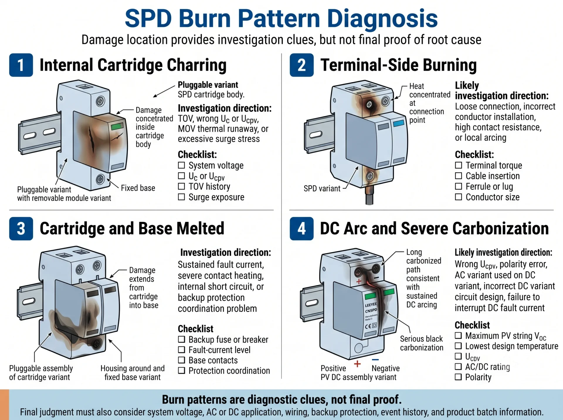
A localização e a forma dos danos visíveis podem ajudar a determinar o que inspecionar primeiro. Padrões de queimadura são pistas de investigação, não provas definitivas.
| Padrão visível | Direção inicial da investigação | Evidências a serem coletadas |
|---|---|---|
| Carbonização concentrada no interior do cartucho | Verificar fuga térmica, TOV, Uc ou Ucpv, degradação repetida e estresse por surto. | Etiqueta completa, tensão medida, histórico de eventos e inspeção interna. |
| Queimadura concentrada em um terminal de parafuso | Verifique a inserção, o torque, o tamanho do condutor, o terminal tubular, a contaminação e o arco elétrico local. | Fotos detalhadas do terminal, amostra do condutor e registros de torque. |
| Cartucho queimado, mas a base parece intacta | Investigue a falha ao nível do módulo, mas não presuma que os contatos da base permanecem seguros. | Modelo base, condição dos contatos, descoloração e inspeção elétrica. |
| Tanto o cartucho quanto a base derreteram. | Verifique a corrente de falha sustentada, o aquecimento dos contatos e a coordenação da proteção. | Dispositivo a montante, dados de curto-circuito e cabeamento completo da derivação. |
| Vários polos danificados simultaneamente | Verifique a sobretensão do sistema, surto de modo comum, evento no neutro ou incidente de alta energia. | Registros de tensão, disposição do aterramento e outros equipamentos danificados. |
| Um polo queima repetidamente | Verifique a tensão nesse caminho, as condições do polo em relação à terra e o aquecimento local recorrente. | Medições por polo e diagrama de fiação. |
| O DPS CC fotovoltaico apresenta longos rastros de carbono | Verifique a classificação CC, Ucpv, polaridade, topologia do circuito e incompatibilidade CA/CC. | Voc da string, temperatura de projeto mais baixa e etiqueta completa do modelo. |
Uma base, bloco terminal ou invólucro severamente queimado não deve ser reutilizado apenas por parecer mecanicamente íntegro.
Como o diagnóstico de queima difere entre SPDs de AC e SPDs de DC PV?
Quadro de distribuição AC
- Tensão nominal e medida L-N e L-L
- Continuidade do neutro e histórico de perda de neutro
- Esquema de aterramento TN, TT ou IT
- Uc para cada caminho de proteção
- Configuração 3+1 versus 4+0
- Coordenação de proteção a montante
- Corrente de curto-circuito prospectiva
Caixa combinadora CC fotovoltaica ou entrada do inversor
- Tensão máxima de circuito aberto da string
- Correção de Voc na temperatura mínima
- Número de módulos em série
- Ucpv e classificação CC exata
- Tensão positiva e negativa em relação à terra
- Polaridade e configuração do circuito
- Comportamento de corrente de falha CC e isolamento
Um DPS fotovoltaico deve ser selecionado com base no projeto real do arranjo. A classe CC comercializada de um inversor não confirma, por si só, a tensão máxima que cada caminho do DPS irá experimentar.
Que evidências são necessárias para determinar por que um SPD queimou?
Uma fotografia em close da área mais escura não é suficiente para um diagnóstico confiável.
| Informação | Por que isso importa | O que fornecer |
|---|---|---|
| Etiqueta completa do DPS | Confirma o modelo, a classificação CA/CC, Uc ou Ucpv, o tipo e as classificações de corrente. | Fotografias nítidas da frente e da lateral. |
| Local do dano | Separa danos no cartucho, terminal, contato da base e condutor. | Fotografias da frente, traseira, lateral, terminal e base. |
| Tensão do sistema | Indica se o DPS foi submetido a uma tensão contínua inadequada. | Tensão nominal e valores medidos reais. |
| Aplicação AC ou DC | Confirma se a classificação do produto corresponde ao circuito. | Diagrama unifilar e informações do equipamento. |
| Esquema de aterramento | Altera a exposição à tensão e o modo de proteção. | Descrição e diagrama de TN-S, TN-C-S, TT ou IT. |
| Proteção de backup | Permite a revisão da coordenação de corrente de falta. | Modelo, classificação e capacidade de interrupção do fusível ou disjuntor. |
| Condutores e terminais | Ajuda a identificar o aquecimento e a formação de arco nas conexões. | Registro de tamanho do cabo, tipo de terminal ou luva, comprimento e torque. |
| Histórico de eventos | Auxilia na distinção entre descargas atmosféricas, manobras, sobretensões temporárias (TOV), perda de neutro e envelhecimento gradual. | Data, condições meteorológicas, alarmes, interrupções e danos nas proximidades. |
| Histórico de lote e instalação | Auxilia na identificação de condições recorrentes no local ou possíveis padrões de lote. | Data de instalação, quantidade afetada, número do lote e casos anteriores. |
Precisa de ajuda para revisar um SPD queimado?
Envie fotos nítidas da etiqueta, da área danificada, da base, dos terminais e do dispositivo a montante, juntamente com a tensão do sistema, aplicação em CA ou CC, diagrama de fiação e informações de proteção.
Fluxo de trabalho diagnóstico de queima do SPD passo a passo
- Confirme que o circuito está em segurança. Não inspecione nem remova o SPD enquanto estiver sob tensão.
- Registe a instalação original. Tire fotografias de plano geral e de plano aproximado antes de mover os condutores.
- Identifique o centro do dano. Determine se o evento teve início no cartucho, na base, no terminal ou no condutor.
- Verifique o modelo completo. O cartucho e a base podem ter códigos de modelo separados.
- Confirme a adequação para AC ou DC. Verifique a aplicação nominal exata.
- Compare Uc ou Ucpv com a tensão real. Inclua condições operacionais anormais e máximas.
- Inspecione a cablagem e a ligação à terra. Confirme se todos os caminhos de proteção estão ligados corretamente.
- Inspecione os terminais e contactos. Procure problemas de binário, virolas, corrosão, descoloração e carbonização.
- Reveja a proteção de reserva. Compare o dispositivo real com os requisitos do fabricante.
- Verifique o histórico de eventos. Reveja os alarmes de relâmpagos, TOV, perda de neutro, comutação e inversor.
- Compare outras falhas. Determine se o padrão é específico do local, do modelo ou do lote.
- Corrija a causa antes da substituição. O novo SPD não é, por si só, a ação corretiva.
Você pode substituir apenas o cartucho do SPD plug-in?
Por vezes—mas apenas após a base, contactos, terminais e o ramo de proteção completo terem sido inspecionados.
A substituição apenas do cartucho pode ser possível quando:
- A base não apresenta fissuras, derretimento ou carbonização
- Os contactos de encaixe não apresentam sobreaquecimento ou perda de pressão
- Os terminais e condutores permanecem sem danos
- A causa raiz foi identificada e corrigida
- O novo cartucho é aprovado para a base exata
- O fabricante permite a substituição do cartucho
Substitua o SPD completo quando:
- A base estiver derretida, rachada, deformada ou carbonizada
- Os contactos estiverem queimados, soltos ou descolorados
- O isolamento dos terminais estiver danificado
- A compatibilidade não puder ser verificada
- A configuração ou classificação original estava incorreta
- A causa permanecer por resolver após queima severa
Como selecionar o SPD de reposição correto
| Parâmetro | O que verificar | Erro comum |
|---|---|---|
| Classificação AC ou DC | Confirme o circuito exato e a aplicação aprovada. | Utilizar um modelo AC num circuito DC fotovoltaico. |
| Uc ou Ucpv | Calcular a partir da tensão de operação contínua e máxima real. | Escolher apenas com base na tensão nominal do sistema. |
| Tipo de SPD | Confirme o Tipo 1, Tipo 2 ou Tipo 1+2 de acordo com a posição de instalação. | Utilizar o Tipo 2 onde possa entrar corrente parcial de relâmpago. |
| In, Imax ou Iimp | Corresponda a capacidade de corrente ao conceito de proteção. | Assumir que o Imax mais elevado resolve todas as falhas. |
| Para cima | Coordene com a tensão de impulso suportável do equipamento protegido. | Aumentar a Uc sem verificar o nível de proteção. |
| Modo de proteção | Confirme a disposição L-N, L-PE, N-PE ou polo-terra fotovoltaico. | Alterar 3+1 e 4+0 sem verificar a ligação à terra. |
| Condições de corrente de falha | Verifique a corrente de curto-circuito prospetiva e as instruções do fabricante. | Ignorar a corrente de falha disponível. |
| Proteção de backup | Coordene o tipo, a classificação e a capacidade de interrupção do fusível ou disjuntor. | Utilizar um dispositivo de proteção universal para cada SPD. |
| Compatibilidade da base | Verifique a combinação exata de cartucho e base. | Assumir que tamanho semelhante significa compatibilidade. |
| Certificação | Confirme o âmbito necessário IEC, EN, UL ou do documento do projeto. | Verificar apenas a etiqueta em vez do âmbito do certificado. |
Trate um SPD queimado como um evento de diagnóstico, não apenas como uma encomenda de peças de substituição. A substituição deve abordar tanto o dispositivo danificado como a condição elétrica que causou ou ampliou o dano.
Perguntas Frequentes sobre SPDs queimados
Um SPD queimado sempre significa baixa qualidade do produto?
Não. Um defeito de produto é uma causa possível, mas TOV, Uc ou Ucpv incorretos, utilização indevida de CA/CC, energia de sobretensão excessiva, ligações soltas, erros de cablagem e proteção inadequada contra correntes de falha podem criar danos semelhantes. A conclusão deve basear-se na evidência completa.
Um raio pode fazer um SPD queimar ou derreter?
Sim. Um evento grave ou repetido relacionado com descargas atmosféricas pode exceder a capacidade de corrente e energia do SPD. A queima visível pode então ser ampliada pela corrente contínua de frequência industrial ou corrente de falha CC.
Um SPD pode queimar sem um raio?
Sim. Perda de neutro, sobretensão temporária, anomalias da rede, eventos de comutação, seleção de tensão incorreta, aquecimento dos terminais, utilização indevida de CA/CC e defeitos internos podem causar danos graves sem descargas atmosféricas.
Por que o SPD queimou, mas o disjuntor não desarmou?
Pode desenvolver-se um calor local intenso sem produzir uma corrente que atinja o limiar de disparo instantâneo do disjuntor. Um impulso curto, uma falha de alta resistência, um arco intermitente ou uma coordenação inadequada dos dispositivos de proteção podem produzir diferentes respostas do disjuntor.
Um SUPD AC pode queimar quando usado em um sistema solar DC?
Sim. Um SPD para AC pode ter características de tensão, circuito e desconexão inadequadas para operação em DC. Use apenas um modelo classificado explicitamente para a tensão DC de PV exata e a configuração do circuito.
Uma terminal solto pode fazer um SPD ficar preto?
Sim. Uma ligação solta ou de alta resistência pode produzir aquecimento concentrado e arcos elétricos. Se o dano mais forte for perto do terminal, verifique o binário de aperto, a preparação dos cabos, as ponteiras, a secção do condutor, a corrosão e os contactos de encaixe.
Devo selecionar um Uc mais alto após uma queima de SPD?
Não automaticamente. Primeiro, confirme a tensão contínua real, o esquema de ligação à terra, o modo de proteção e o risco de TOV. Uma Uc mais elevada pode melhorar a margem de tensão, mas também pode afetar o nível de proteção de tensão.
Um Imax mais alto evitará que um SPD queime?
Não em todos os casos. Um Imax mais elevado não corrige TOV, Uc incorreta, utilização indevida de CA/CC, terminais soltos, erros de cablagem ou proteção de reserva inadequada.
Posso substituir apenas o módulo de encaixe?
Apenas quando a base, os contactos, os terminais e os condutores permanecem intactos, a causa da falha foi corrigida e o cartucho de substituição está aprovado para a base exata.
O que devo enviar ao fornecedor SPD para diagnóstico?
Envie fotografias do rótulo completo, da área danificada, da base, dos terminais, da fiação e do dispositivo de proteção a montante. Também forneça a tensão do sistema, a aplicação CA ou CC, o arranjo de aterramento, o diagrama de fiação, o tamanho do condutor, a data de instalação, o número do lote e os detalhes do evento.
Revisão técnica e base de referência
Este guia é revisto como um recurso de diagnóstico prático B2B. A atribuição final da falha pode exigir medições no local, exame destrutivo ou análise laboratorial independente.
Referências técnicas
- IEC 61643-11 — Dispositivos de proteção contra sobretensões de baixa tensão para sistemas de energia CA: requisitos e métodos de ensaio.
- IEC 61643-31 — Dispositivos de proteção contra sobretensões para instalações fotovoltaicas: requisitos e métodos de ensaio.
- Instruções do fabricante para Uc, Ucpv, comportamento TOV, proteção de reserva e proteção a montante máxima admissível.
- Requisitos específicos do projeto para instalação elétrica, proteção contra descargas atmosféricas e corrente de falha.
Precisa de uma recomendação de SPD de reposição?
Envie fotos do seu SPD danificado, a etiqueta do modelo completa, a tensão do sistema, o esquema elétrico e as informações sobre a proteção de reserva. A LEEYEE pode ajudá-lo a identificar a provável direção da investigação e a confirmar os parâmetros de substituição CA ou PV CC adequados.
Nota técnica: Esta página apoia a investigação inicial e a seleção da substituição. Não substitui os ensaios elétricos no local, as instruções específicas do fabricante ou um relatório formal de falha laboratorial.
