
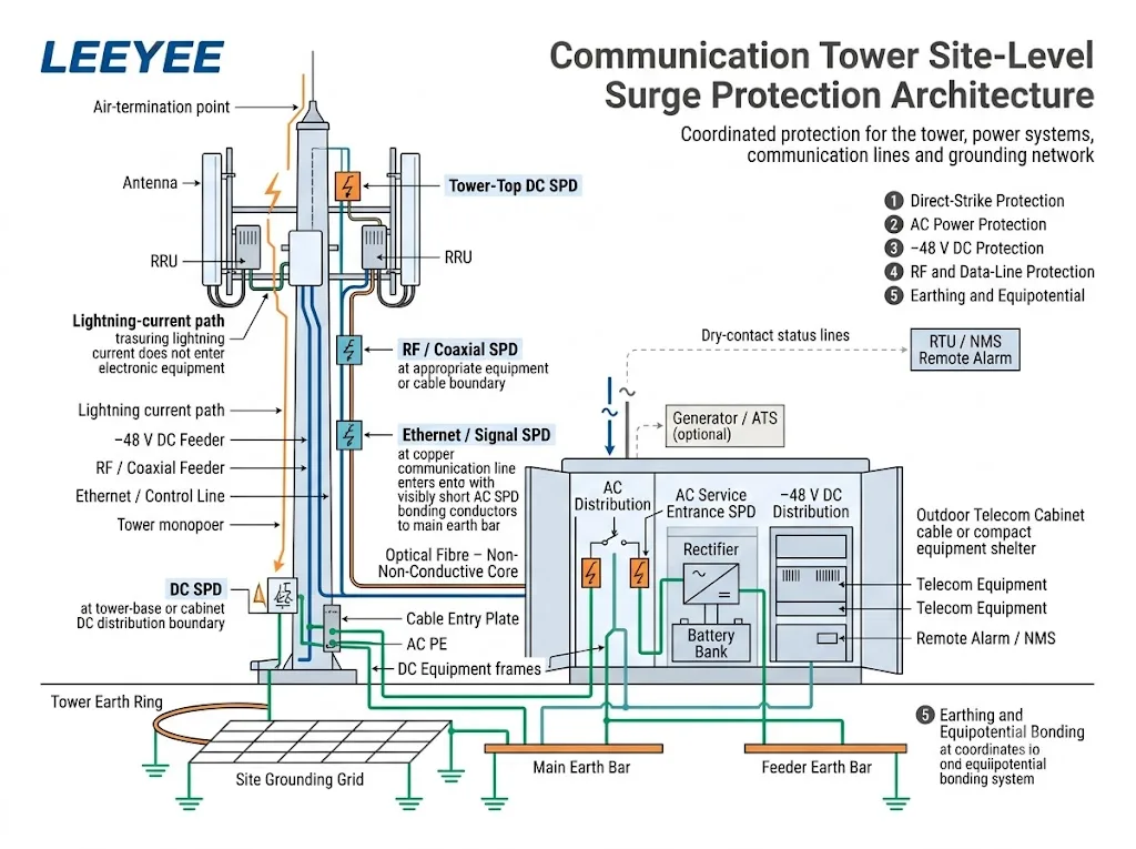
A proteção contra surto de torre de comunicação deve cobrir todo o site de rádio, não apenas um SPD dentro de um gabinete externo. O mesmo princípio de nível de site se aplica à proteção contra surto de site celular, proteção contra raios de torres de telecomunicações e muitas instalações de estações base de rádio.
A estrutura da torre, alimentação CA, feeders −48 V DC, interfaces de antena, linhas de dados de cobre, armários de equipamentos e rede de aterramento do site devem funcionar como um único sistema de proteção coordenado.
Índice
Resposta rápida
Um site de torre de comunicação normalmente precisa de quatro funções coordenadas: um sistema de proteção contra raios externo, um sistema de aterramento do site, ligação equipotencial e SPDs corretamente selecionados em linhas de potência e sinal condutivas.[1][2]
Alimentação CA, −48 V DC, feeders RF ou coaxiais, Ethernet, PoE e linhas de controle requerem diferentes dispositivos de proteção. Cada SPD deve corresponder ao circuito real, limite de instalação e exposição esperada a surtos.
Significado do comprador: envie ao fornecedor a arquitetura do site, tensões de operação, arranjo de aterramento, interfaces de cabo e posições propostas de SPD. Um pedido de apenas “um SPD para uma torre de comunicação” não é suficiente para uma seleção confiável.
Como a Proteção contra Raios e Surto da Torre de Comunicação Trabalham Juntas
Uma descarga direta pode enviar corrente através da estrutura da torre, rede de aterramento, blindagens de cabo e serviços conectados. Equipamentos eletrônicos podem, portanto, ser danificados mesmo quando o raio não atinge diretamente um porta de equipamento.
A ITU-T K.112 fornece procedimentos práticos para proteção contra raios, aterramento e ligação em estações base de rádio autônomas e em telhados.[2] A ITU-T K.119 avalia quatro partes conectadas do sistema de proteção.[3]
Terminação aérea e caminho de corrente.
O sistema externo intercepta raios diretos e fornece um caminho projetado em direção à terra.
Sistema de aterramento do site.
A torre, abrigos e estruturas associadas conectam-se a uma rede coordenada de terminação de terra.
Ligação equipotencial.
Estruturas metálicas, blindagens de cabo, quadros de equipamentos e condutores de proteção são coordenados para limitar diferenças de potencial.
Dispositivos de proteção contra surtos.
As SPDs limitam surtos conduzidos em circuitos de CA, CC, RF, dados e controle nas fronteiras relevantes.
O que Inclui uma Arquitetura Completa de Proteção de Site de Torre?
Comece com o local físico em vez de um catálogo de produtos. Rastreie os caminhos de corrente de raio esperados, identifique cada cabo condutor que cruza uma fronteira de proteção e atribua a função de proteção correta a esse local.
- Avalie a torre e sua exposição ao raio. Confirme se a instalação é uma torre autônoma, local em telhado, monopolo, mastro de transmissão ou estação sem fio remota. A IEC 62305-2 fornece um procedimento de gestão de risco para selecionar medidas de proteção apropriadas.[5]
- Defina o sistema de proteção contra descargas atmosféricas externas. Confirme o arranjo da terminação aérea, o caminho da corrente, a terminação à terra, os requisitos de separação e a proteção contra tensões de contato e de passo.[6]
- Estabeleça o conceito de aterramento do local. Identifique a estrutura de aço da torre, o gabinete, o abrigo, a placa de entrada de cabos, as barras de aterramento do alimentador, o PE CA, as estruturas de equipamentos CC e os racks de equipamentos de rádio.
- Mapeie todos os serviços condutores. Inclua AC de utilidades, geradores, CC −48 V, alimentadores coaxiais, Ethernet, PoE, RS485, AISG, linhas de alarme, sensores e circuitos de iluminação de torres.
- Marque cada limite de proteção. Identifique onde os cabos entram ou saem de uma área equipotencial e onde equipamentos sensíveis estão conectados.
- Selecione e coordene os SPD. Use o padrão SPD de CA, CC ou telecomunicações aplicável e verifique os parâmetros exigidos em cada posição.[8][9][11][12]
- Plan commissioning and maintenance. Keep indicators, remote contacts, bonding points and replaceable modules accessible for inspection.
Onde os Surges Podem Entrar em um Site de Torre de Comunicação?
The tower is the most visible exposure point, but it is not the only path. Every conductive connection between outdoor equipment, the tower, the power source, the cabinet and sensitive electronics requires review.
| Entry path | Typical exposure | Protection function | Buyer must confirm |
|---|---|---|---|
| Tower or mast | Direct strike and lightning-current flow through the structure | External LPS, current path, earth termination and bonding | Tower type, height, layout, risk assessment and LPS design |
| AC supply | Utility line, overhead section, generator, ATS or site distribution | AC SPD coordinated with the supply and lightning exposure | Voltage, phases, earthing system, Uc, Iimp or In, Up and backup protection |
| −48 V DC feeder | Long copper feeder between rectifier, DC distribution and tower-mounted radio | Low-voltage DC SPD at the required protection boundaries | Maximum bus voltage, polarity, bonding, protection modes and SPD positions |
| RF or coaxial line | Metallic antenna feeder, connector and cable shield | RF SPD and shield bonding at the designed boundary | Connector, impedance, frequency, RF power, insertion loss and VSWR |
| Ethernet or PoE | Outdoor copper network cable between different equipment areas | Data-line SPD matched to Ethernet and PoE performance | Data rate, PoE type, power, protected pairs and shielding |
| Control or alarm line | RS485, AISG, sensor, dry-contact or navigation-light circuit | Signal SPD selected for the real operating circuit | Voltage, protocol, pair count, current and terminal arrangement |
An all-dielectric optical fibre does not conduct surge current through the glass fibre. Metallic armour, strength members, hybrid power conductors, equipment housings and associated copper circuits still require assessment.
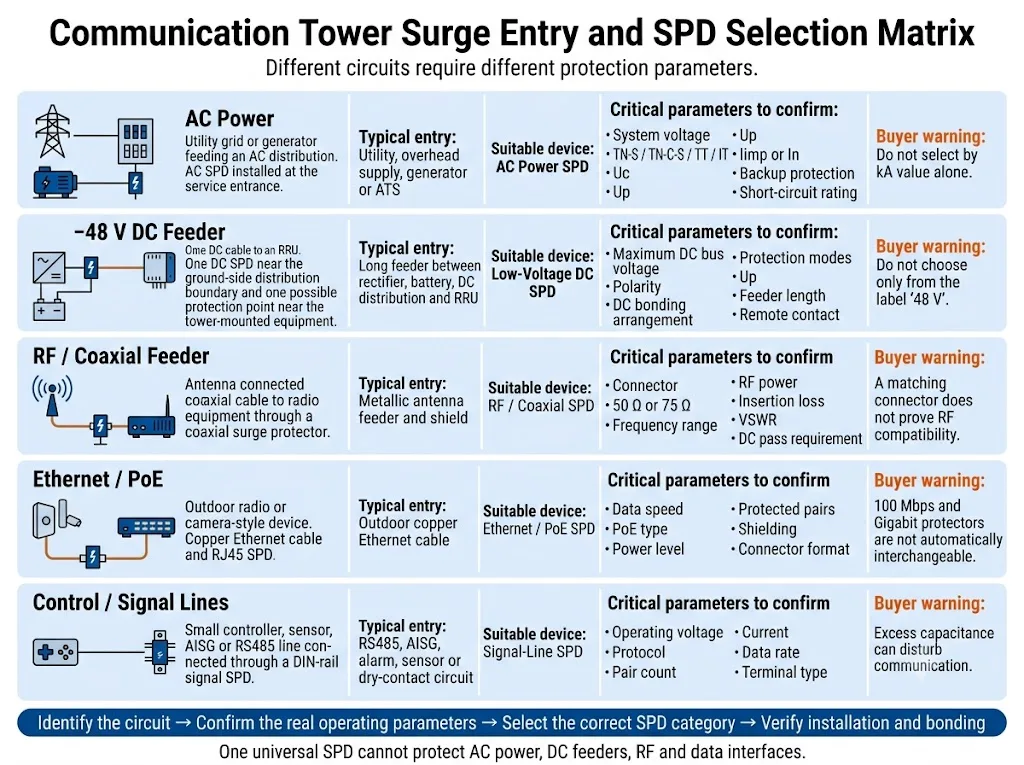
Procurement conclusion: identify the circuit before comparing discharge-current ratings. A high kA value or matching connector does not prove compatibility with the operating voltage, protection mode, frequency or data performance.
Como a Entrada CA Deve Ser Protegida?
The AC protection arrangement depends on the tower exposure, incoming supply, external lightning protection system and upstream distribution.
A stand-alone tower with an exposed incoming service can require a different solution from rooftop equipment supplied through a protected building distribution system.
IEC 61643-11:2025 specifies requirements and test methods for SPDs connected to AC low-voltage power systems.[9] IEC 61643-12:2020 addresses AC SPD selection, operation, location and coordination.[10]
Confirm these AC parameters
- System voltage and Uc: use the real maximum continuous operating voltage, not only the nominal network label.
- Earthing system: TN-S, TN-C-S, TT and IT arrangements can require different protection modes.
- Lightning-current exposure: confirm whether Type 1, Type 1+2 or another coordinated arrangement is required.
- Voltage protection level: coordinate Up with the equipment withstand level and downstream protection.
- Discharge parameters: confirm Iimp, In or Imax according to the SPD classification and project requirement.
- Short-circuit conditions: verify prospective short-circuit current, SPD short-circuit capability and backup protection.
- Alternative power paths: include generators, ATS circuits and any other connected source.
- Connection path: keep the complete SPD connection short and direct because conductor inductance adds voltage during a fast surge.
Como o Feeder −48 V DC Deve Ser Protegido?
Radio sites commonly use rectifiers and batteries to supply tower-mounted radio equipment through long copper DC feeders. A transient can enter from the tower side or appear through a potential difference between tower equipment and ground-level equipment.
IEC 61643-41:2025 applies to SPDs connected to DC power circuits and equipment rated up to 1,500 V DC.[11] The selected device must still be designed and rated for the actual low-voltage telecom circuit.
Do not select from the label “48 V” alone
The DC bus can rise above its nominal value during rectifier operation, battery charging or system adjustment. Confirm the highest continuous operating voltage before fixing the SPD voltage rating.
| DC question | Por que isso importa | Information to provide |
|---|---|---|
| Maximum bus voltage | An unsuitable continuous voltage can cause premature ageing or an inappropriate protection level. | Rectifier range, battery float voltage, charging voltage and abnormal operating limits. |
| DC bonding arrangement | Protection modes depend on the relationship between DC+, return, DC− and PE. | Single-line diagram and the project bonding or earthing arrangement. |
| Feeder exposure | A long feeder crossing different equipment areas can require coordinated protection at more than one boundary. | Feeder length, route, tower height, radio locations and proposed SPD positions. |
| Status monitoring | A fault at an unmanned site can remain unnoticed without a remote signal. | Required NO, NC or changeover contact and the RTU or NMS alarm logic. |
Como as Linhas de RF, Ethernet e Controle Devem Ser Protegidas?
Each protector must preserve the normal performance of its circuit while limiting transient voltage. A device can fit mechanically and still be electrically unsuitable.
RF and coaxial feeders
Confirm the connector type, characteristic impedance, operating frequency, RF power, insertion loss, return loss or VSWR, DC-pass requirement and environmental rating.
The cable shield and RF protector should be bonded at the position required by the site design. Protection or bonding at both ends can be appropriate in some architectures, but it is not a universal rule.
Ethernet and PoE
IEC 61643-21:2025 covers SPDs for telecommunications and signalling networks, including networks that provide power on the same line, such as PoE.[12]
Confirm the Ethernet speed, PoE type, maximum power, protected pairs, shielding and acceptable insertion performance. A device designed for 100 Mbps or lower-power PoE should not be assumed suitable for Gigabit Ethernet or higher-power PoE.
RS485, AISG, alarm and sensor circuits
Match the SPD to the operating voltage, maximum signal level, number of conductors, current, data rate, reference conductor and terminal arrangement.
Excess capacitance or an unsuitable protection level can disturb communication even when the SPD itself remains operational.
Por que o Aterramento e a Ligação Equipotencial Determinam o Resultado?
An SPD diverts surge current into the bonding and earthing network. If that path is long, indirect, corroded or poorly coordinated, the voltage at the protected equipment can be significantly higher than the SPD datasheet Up value.
Site bonding is not simply a collection of earth rods. Its purpose is to reduce dangerous potential differences between the tower, cabinet, shelter, cable shields, AC PE, DC equipment and other conductive systems during a lightning event.[2][7]
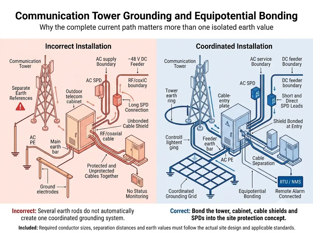
One earth-resistance value is not the complete answer
Earth resistance is important, but the result also depends on conductor routes, inductance, network geometry, soil conditions, current sharing, connection quality, corrosion and bonding position.
Do not promise that every tower is protected when the measured resistance is below one fixed value. Acceptance criteria must follow the site specification, local regulations, measurement method and qualified lightning-protection design.
Bonding points that normally require review
- Tower steelwork, monopole or mast base.
- External down-conductors where separately installed.
- Tower-base earth bar and equipment-room main bonding bar.
- Outdoor cabinet frame, door, cable-entry plate and internal PE bar.
- Coaxial cable shields and feeder earth bars.
- AC PE, generator earthing and ATS-related bonding.
- Rectifier, battery rack, DC distribution and telecommunications racks.
- Metallic cable trays, fences and auxiliary tower equipment where required by the design.
Por que o Limite Torre-Cabinete é Crítico?
The point where cables leave the tower and enter an outdoor cabinet or shelter combines exposed conductors, cable shields, bonding connections and sensitive electronic ports.
- Place the correct SPD close to the relevant cable-entry or equipment boundary.
- Bond cable shields at the feeder earth bar or entry point defined by the site design.
- Use short, direct SPD bonding conductors.
- Separate protected and unprotected cable sections to reduce surge re-coupling.
- Avoid unnecessary loops, sharp routing changes and excess conductor length.
- Integrate the tower, cabinet and shelter into the coordinated site bonding system.
- Keep indicators, replaceable modules and remote terminals accessible after installation.
Como Alarmes Remotos e Manutenção Devem Ser Planejados?
Many communication towers are remote or unmanned. A failed module, disconnected bonding conductor or corroded connection can remain unnoticed until another surge event.
ITU-T K.119 addresses visual inspection, measurement, analysis and other methods used to assess the reliability of radio base station lightning protection and earthing systems.[3] IEC 62305-4 also covers inspection, maintenance and testing of surge protection measures.[7]
Remote monitoring can report
- Normal or failed SPD module status.
- Module removal where the SPD mechanism supports it.
- NO, NC or changeover dry-contact state.
- An alarm input to an RTU, PLC, cabinet controller or network-management system.
Remote indication supports maintenance, but it does not replace physical inspection. Corrosion, loose conductors, enclosure damage and incorrect replacement modules may not be detected by one auxiliary contact.
Inspect the protection system
- During initial commissioning and acceptance.
- At the scheduled preventive-maintenance interval.
- After a recorded lightning event or unexplained equipment fault.
- After adding antennas, radios, power equipment or another cabinet.
- After grounding work, civil work or cable-route changes.
- When an SPD indicator or remote alarm changes state.
Como o Tipo de Site Altera a Decisão de Proteção?
Stand-alone ground tower
This site normally has its own tower, earth network, utility or generator supply, equipment enclosure and several exposed copper conductors. It can require direct-strike protection plus coordinated AC, DC, RF and signal-line SPDs.
Rooftop radio installation
Rooftop equipment shares the building lightning protection system, main earthing terminal and electrical distribution. The designer must review separation distance, protection zones and coordination with existing building SPDs.
Remote microwave or monitoring site
This site may use batteries, solar power, a small AC source, long Ethernet or control lines and limited maintenance access. The selection must follow the real conductive interfaces and power architecture.
Conclusão de engenharia: “communication tower” does not identify one universal SPD package. The physical site and cable architecture determine which protection functions are required.
Como um Comprador Deve Verificar o Pacote SPD Proposto?
Diagrams explain the protection concept, but they are not product approvals. Before approving a tower-site package, verify each proposed model against the circuit it will protect.
Request model-specific evidence
LEEYEE is a specialized surge protection and low-voltage protection supplier. CNSPD is LEEYEE’s surge protection-focused platform for global technical buyers.
A certificate for one series or configuration must not be treated automatically as approval for every voltage, pole arrangement, connector or OEM variant. Confirm the exact document scope before project submission.
O Que Deve Ser Confirmado Antes de Fazer o Pedido?
Prepare the following information before requesting model recommendations, samples, technical files or an OEM quotation.
Solicitar uma Revisão da Configuração SPD para Torre de Comunicação
Share the site single-line diagram, tower and cabinet layout, AC supply details, maximum DC bus voltage, cable interfaces and grounding drawing with LEEYEE.
Proposed models and installation positions must be confirmed against the actual equipment instructions, local electrical rules, project specification and qualified lightning-protection design.
Perguntas Frequentes sobre Proteção contra Surto em Torres de Comunicação
Can one AC SPD protect the complete communication tower site?
Does every communication tower require a Type 1 SPD?
Where should the −48 V DC SPD be installed?
Can a PV DC SPD be used for a 48 V telecom system?
Does optical fibre remove the need for surge protection?
Should an RF surge protector be installed at both cable ends?
Is a low grounding-resistance value enough?
Is remote alarm useful at a tower site?
Which documents should an OEM buyer request?
Referências
- International Telecommunication Union, ITU-T K.56 (05/2021), Protection of radio base stations against lightning discharges. Official ITU publication.
- International Telecommunication Union, ITU-T K.112 (05/2021), Lightning protection, earthing and bonding: Practical procedures for radio base stations. Official ITU publication.
- International Telecommunication Union, ITU-T K.119 (12/2016), Conformance assessment of radio base stations regarding lightning protection and earthing. Official ITU publication.
- International Electrotechnical Commission, IEC 62305-1:2024, Protection against lightning – Part 1: General principles. Official IEC publication.
- International Electrotechnical Commission, IEC 62305-2:2024, Protection against lightning – Part 2: Risk management. Official IEC publication.
- International Electrotechnical Commission, IEC 62305-3:2024, Protection against lightning – Part 3: Physical damage to structures and life hazard. Official IEC publication.
- International Electrotechnical Commission, IEC 62305-4:2024, Protection against lightning – Part 4: Electrical and electronic systems within structures. Official IEC publication.
- International Electrotechnical Commission, IEC 61643-01:2024, Low-voltage surge protective devices – Part 01: General requirements and test methods. Official IEC publication.
- International Electrotechnical Commission, IEC 61643-11:2025, Low-voltage surge protective devices – Part 11: Surge protective devices connected to AC low-voltage power systems – Requirements and test methods. Official IEC publication.
- International Electrotechnical Commission, IEC 61643-12:2020, Low-voltage surge protective devices – Part 12: Surge protective devices connected to low-voltage power systems – Selection and application principles. Official IEC publication.
- International Electrotechnical Commission, IEC 61643-41:2025, Low-voltage surge protective devices – Part 41: Surge protective devices connected to DC low-voltage power systems – Requirements and test methods. Official IEC publication.
- International Electrotechnical Commission, IEC 61643-21:2025, Low-voltage surge protective devices – Part 21: Surge protective devices connected to telecommunications and signalling networks – Requirements and test methods. Official IEC publication.
- International Electrotechnical Commission, IEC 61643-31:2018, Low-voltage surge protective devices – Part 31: Requirements and test methods for SPDs for photovoltaic installations. Official IEC publication.
