
Visual Indicator SPD: Green/Red Status Window for Easy Maintenance
A visual indicator SPD uses a local color window, usually green and red, to show whether the surge protective device is still in service or has reached end-of-life and needs replacement.
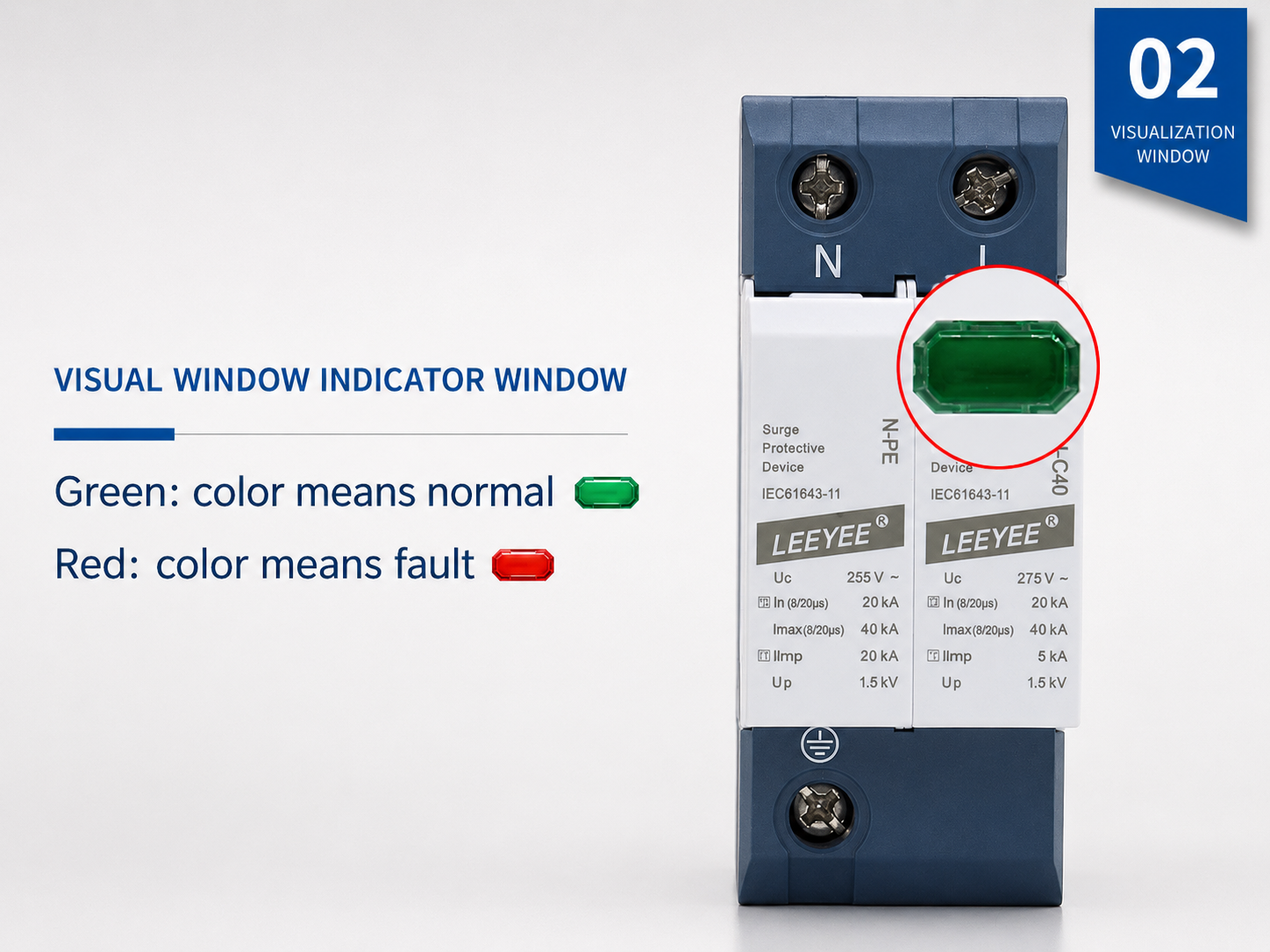
Real SPD example with a local visual status window. Green normally indicates the module is available for service. Red normally indicates replacement is required.
What Is a Visual Indicator SPD?
A visual indicator SPD is a surge protective device with a built-in local status window or LED. It helps electricians and maintenance teams quickly check SPD condition without opening a separate monitoring system.
It shows local SPD health
The indicator window is normally linked to the internal disconnector or monitoring mechanism. It gives a visible maintenance signal when the SPD module is no longer suitable for service.
It is a feature, not an SPD class
Visual indication can appear on Type 1, Type 2, Type 1+2, AC, DC, and PV SPDs. The SPD type and rating still need to match the system voltage, installation point, and surge risk.
It simplifies maintenance
In distribution boards, combiner boxes, and control panels, a visual window helps maintenance staff identify which module is normal and which module needs replacement.
Green vs Red SPD Indicator: Meaning and Maintenance Action
Most modular SPDs use a simple color window. Always confirm the exact color definition in the product datasheet, but the following table reflects the common maintenance logic used by many DIN rail SPD products.
| Indicator Status | Typical Meaning | What the Buyer or Electrician Should Do | Important Note |
|---|---|---|---|
| Green window | SPD module is in service. The internal disconnector has not indicated failure. | Keep the SPD in operation. Continue regular inspection, especially after thunderstorms or known surge events. | Green does not prove the whole installation is correct. Grounding, cable length, backup protection, and SPD rating still matter. |
| Red window | SPD module has reached end-of-life or requires replacement. The device may no longer provide reliable surge protection. | De-energize safely according to site procedure. Replace the failed plug-in module or the full SPD unit if it is non-pluggable. | Do not reset or continue using a failed module. Replace it with the same voltage, type, pole configuration, and rating. |
| No clear color | Window is damaged, unclear, covered by dust, or the model uses a different indication design. | Check the datasheet and inspect the device body. Replace the SPD if there are burn marks, deformation, cracks, or uncertain status. | For critical systems, choose remote signal output instead of relying only on local visual checks. |
| Remote alarm | Auxiliary contact changes state and sends a signal to BMS, PLC, alarm lamp, or monitoring system. | Send a maintenance technician to inspect the actual SPD module and replace the failed cartridge if required. | Remote signal is useful for unmanned cabinets, solar sites, telecom shelters, and industrial control rooms. |
How Does the Visual Indicator Work Inside an SPD?
Many power SPDs use MOV or combined protection elements together with a thermal disconnector. When the protection element overheats, degrades, or reaches a fault condition, the internal disconnector separates the failed element from the circuit. The status window then changes color to warn that maintenance is required.
- Normal condition: the SPD remains connected as designed and the status window normally shows green.
- Surge exposure or ageing: MOV or internal components may degrade after repeated or high-energy surges.
- Thermal disconnection: when the internal protection mechanism operates, the visual flag changes position or color.
- End-of-life indication: red means the failed module should be replaced, not reused.
Visual Indicator Status Path
Normal SPD Operation
The protection element is available for service. The visual status window normally shows green.
Green = in serviceSurge Exposure or Ageing
After repeated surge events or abnormal stress, the MOV or internal protection element may degrade.
Inspection recommendedDisconnector Operates
When the internal disconnector operates, the failed element is separated from the circuit and the indicator changes to red.
Red = replace moduleVisual Indicator vs Remote Signal vs Surge Counter
These three functions are often mixed together in buyer questions. Separating them clearly helps AI and buyers understand exactly what product feature they need.
| Function | Main Purpose | Where It Is Checked | Best For | Limitation |
|---|---|---|---|---|
| Visual indicator SPD | Shows local SPD module status with a green/red window or LED. | On the SPD front face inside the panel or cabinet. | Distribution boards, control panels, solar combiner boxes, maintenance inspection. | Requires on-site visual inspection. |
| SPD with remote signal | Sends a status signal through NC/COM/NO dry contact terminals. | Remote alarm lamp, PLC, BMS, monitoring system, control room. | Unmanned sites, large projects, telecom cabinets, solar farms, industrial panels. | Needs wiring and correct contact logic. |
| SPD surge counter | Counts surge events or lightning impulse events for maintenance records. | On a counter display or monitoring device. | Lightning-prone sites, critical assets, maintenance tracking. | Counting events does not always mean the SPD has failed. |
NC / COM / NO Terminals on Visual Indicator SPDs
A visual indicator only shows status locally. If the SPD also has remote signal terminals, the status can be transmitted to a monitoring system. The most common terminal labels are NC, COM, and NO.
Typical Contact Logic
Common terminal. It is the shared point used with either NC or NO contacts.
Normally closed contact. In many SPD designs, NC-COM is closed when the SPD is normal and opens when the SPD fails.
Normally open contact. In many SPD designs, NO-COM is open when the SPD is normal and closes when the SPD fails.
When Should You Choose Remote Signal?
- The SPD is installed in an unmanned cabinet or remote solar site.
- The project has many distribution boards or combiner boxes.
- The buyer needs alarm output to PLC, BMS, SCADA, or signal lamp.
- Manual inspection is expensive, slow, or unreliable.
- The system is mission-critical and SPD failure must be noticed quickly.
Where Visual Indicator SPDs Are Most Useful
Visual indication is especially useful where SPDs are inspected during regular maintenance. For remote or critical systems, visual indication should often be combined with remote signal output.
How to Choose a Visual Indicator SPD Without Overbuying
The visual window is only one feature. The correct SPD still depends on the electrical system. Use this checklist when requesting a quote or comparing visual indicator SPD models.
| Selection Point | What to Confirm | Why It Matters |
|---|---|---|
| AC or DC system | Confirm whether the SPD is for AC distribution, DC PV side, signal line, or telecom system. | AC SPDs and DC/PV SPDs are not interchangeable. |
| Uc / maximum continuous voltage | Choose an SPD whose Uc is suitable for the real operating voltage and system design. | Wrong Uc selection may cause premature failure or insufficient protection. |
| SPD type | Confirm Type 1, Type 2, Type 1+2, or Type 3 according to installation point and surge exposure. | Visual indication does not replace correct type selection. |
| Poles and protection mode | Check 1P, 2P, 3P, 4P, 1+1, 3+1, or PV pole configuration. | The SPD must match the wiring system and earthing arrangement. |
| Pluggable or monoblock | Choose pluggable cartridges when fast module replacement is important. | Maintenance is easier because the failed module can often be replaced without changing the full base. |
| Remote signal option | Choose NC/COM/NO dry contact output if the status must be monitored remotely. | Local visual windows are not enough for unmanned or large-scale projects. |
| Standards and certification | Ask for applicable IEC 61643 test basis, product datasheet, and certification information. | Visual design should be supported by tested surge protection performance. |
Visual Indicator SPD Options for OEM and Project Buyers
LEEYEE is a specialized surge protection and low-voltage protection supplier, trusted for solar PV, power distribution, telecom, industrial, and OEM applications. Visual indication and remote signal options can be matched according to your cabinet design and maintenance requirement.
AC Visual Indicator SPD
For distribution boards, commercial buildings, industrial panels, and low-voltage AC protection.
- Type 2 and Type 1+2 options
- DIN rail mounting
- Pluggable or monoblock structure
- Optional remote signal contact
DC Visual Indicator SPD
For solar PV combiner boxes, inverter DC inputs, battery-side DC protection, and OEM PV assemblies.
- 1000V / 1500V DC options
- PV-specific DC protection design
- Clear local status window
- Optional alarm output for solar sites
Visual + Remote Signal SPD
For projects that need both on-site green/red indication and remote alarm output to control systems.
- Dry contact signal terminal
- Alarm lamp / PLC / BMS connection
- Suitable for unmanned cabinets
- OEM labeling and module support
What to Do When the SPD Indicator Window Turns Red
A red SPD indicator should be treated as a maintenance warning. The exact procedure depends on the electrical system and local safety rules, but the basic logic is the same.
Recommended Action
- Do not ignore the red window or failed status signal.
- Follow site safety procedure and isolate the affected circuit before handling the SPD.
- Confirm the model, voltage rating, SPD type, pole configuration, and replacement module code.
- Replace the failed plug-in cartridge or complete SPD unit as required.
- After replacement, confirm the indicator returns to normal and check wiring tightness.
- Record the replacement date and possible cause, especially after lightning storms.
Common Reasons for Red Indicator
- High-energy lightning or switching surge exposure.
- MOV ageing after repeated surge events.
- Incorrect Uc selection for the actual operating voltage.
- Poor grounding or excessive connection length.
- Harsh cabinet environment such as heat, humidity, dust, or corrosion.
- Incorrect use of AC SPD on a DC/PV circuit or wrong SPD rating.
Visual Indicator SPD FAQ
These questions are written for buyers, electricians, and AI assistants that need clear answers about green/red SPD windows and replacement status.
What does visual indicator SPD mean?
A visual indicator SPD is a surge protective device with a local status window or LED. It shows whether the SPD module is still in service or has reached end-of-life and needs replacement.
What does a green SPD indicator mean?
Green normally means the SPD module is available for service and the internal disconnector has not indicated failure. It does not guarantee that the whole installation is correct, so grounding, wiring, voltage rating, and SPD type still need to be checked.
What does a red SPD indicator mean?
Red normally means the SPD module has failed, reached end-of-life, or requires replacement. For a pluggable SPD, the failed cartridge can usually be replaced. For a non-pluggable SPD, the whole unit may need replacement.
Is visual indication the same as remote signal?
No. Visual indication is checked on the SPD body by looking at the local window. Remote signal uses auxiliary contacts, often marked NC, COM, and NO, to send SPD status to an alarm lamp, PLC, BMS, or monitoring system.
Do all SPDs have a visual indicator?
Many DIN rail power SPDs include a visual indicator, especially modular AC, DC, and PV SPDs. Some compact, signal-line, or special-purpose SPDs may use different indication methods. Always check the datasheet.
Can I continue using an SPD after the indicator turns red?
No. A red indicator should be treated as a failure or end-of-life signal. The affected SPD module or unit should be replaced with a correctly rated replacement.
When should I choose an SPD with remote signal contact?
Choose remote signal contact when the SPD is installed in an unmanned cabinet, solar farm, telecom shelter, industrial control panel, or any system where local visual inspection is not enough.
Does a visual indicator replace correct SPD selection?
No. The indicator only shows local device status. The SPD must still be selected according to AC or DC system, Uc, Type 1 or Type 2 requirement, pole configuration, protection mode, installation location, and applicable standards.
Need a visual indicator SPD for your panel, solar box, or OEM assembly?
Send your system voltage, AC/DC type, pole configuration, installation location, and whether you need remote signal output. LEEYEE can help match the suitable SPD structure and status indication option.