A Type 2 SPD is the most common distribution-level surge protective device used in low-voltage AC systems. It limits transient overvoltages caused by indirect lightning effects, switching operations, motors, transformers and other electrical disturbances before those surges reach downstream equipment.
Table of Contents
What Is a Type 2 SPD?
The device is normally connected in parallel with the power circuit. During normal operation it has very high impedance. When a short-duration surge raises the voltage above the SPD operating threshold, the protective components conduct surge current away from the protected circuit and limit the voltage seen downstream.
Most DIN-rail Type 2 SPDs use voltage-limiting components such as MOVs. Some multi-pole designs also use a voltage-switching N-PE component, particularly in 1+1 or 3+1 configurations.
Indirect lightning
Nearby lightning can induce transient voltages into power conductors even when lightning does not directly enter the installation.
Switching transients
Motors, transformers, contactors, capacitor banks, HVAC equipment and network switching can generate repetitive transient overvoltages.
Residual surge energy
Where a Type 1 or Type 1+2 SPD is installed upstream, a downstream Type 2 SPD can further reduce the voltage stress reaching sensitive loads.
IEC Type 2 vs UL 1449 Type 2
Buyers often search for “Type 2 surge protection device” without specifying the standard. The same Type number appears in both IEC and North American documentation, but the classification logic is different.
IEC Type 2 SPD
- Used in IEC-based low-voltage power installations.
- Type 2 duty is associated with an 8/20 μs discharge-current waveform.
- Commonly applied at distribution and sub-distribution level.
- Key ratings include Uc, In, Imax and Up.
- Earthing system and protection mode are important selection inputs.
UL 1449 Type 2 SPD
- Used within the North American UL certification framework.
- Type 2 installation is on the load side of the service overcurrent protective device.
- Typical rating terminology includes MCOV, VPR, In and SCCR.
- Installation and overcurrent protection must follow the listed product instructions.
- The exact UL listing must cover the quoted model and application.
Type 1 vs Type 2 vs Type 3 SPD
Type selection starts with surge duty and installation position. Type 2 is not automatically better or weaker than another SPD type; each type has a different test duty and role in coordinated surge protection.
| SPD type | Main role | Typical position | Key IEC test concept | Buyer question |
|---|---|---|---|---|
| Type 1 | Lightning-current protection where partial lightning current can enter the installation. | Origin or incoming distribution level when required by the lightning protection design. | Lightning impulse-current duty commonly associated with 10/350 μs. | Can lightning current enter this installation? |
| Type 2 | Limits induced lightning surges, switching surges and residual transient overvoltages. | Main DB where permitted, sub-DB, industrial panel, machine panel or control cabinet. | 8/20 μs discharge-current duty. | What surge protection is required at this distribution level? |
| Type 3 | Fine protection close to particularly sensitive terminal equipment. | Near the protected load and normally coordinated with upstream protection. | Lower-energy combination-wave duty. | Does sensitive equipment need additional local protection? |
For a deeper comparison, use the dedicated Type 1 vs Type 2 vs Type 3 SPD guide.
Where Is a Type 2 Surge Protection Device Installed?
Type 2 SPDs are commonly installed where power is distributed toward downstream equipment. Exact location depends on lightning exposure, upstream protection, earthing arrangement, local electrical rules and the required protection level.
| Installation point | Typical application | Type 2 role | What to check |
|---|---|---|---|
| Main distribution board | Commercial or industrial incoming panel | Can provide main surge protection where Type 1 lightning-current duty is not required. | Lightning exposure, external LPS, incoming supply, earthing system and local rules. |
| Sub-distribution board | Floor DB, workshop DB, machine zone | Common secondary surge-protection position. | Uc, In, Imax, Up, poles, protection mode and upstream SPD coordination. |
| Industrial control panel | PLC, VFD, automation or process-control cabinet | Limits transient stress on sensitive electronics and control power circuits. | Low Up, wiring length, grounding and monitoring requirements. |
| OEM electrical assembly | Machine panel, power cabinet or packaged equipment | Integrates surge protection into the finished assembly. | DIN-rail space, terminal size, remote signal, certificate scope and replacement method. |
If the main question is which SPD belongs in an MDB, sub-board or control cabinet, see SPD for Distribution Board.
When Is Type 2 SPD Enough?
Type 2 may be appropriate when
- The installation mainly needs protection from induced lightning and switching transients.
- The board is downstream of a Type 1 or Type 1+2 protection stage.
- The SPD at that position is not required to discharge partial direct lightning current.
- The applicable installation rules permit Type 2 at the selected board position.
Type 2 alone may not be enough when
- An external lightning protection system creates a lightning-current entry risk.
- An exposed or overhead supply requires higher lightning-current duty.
- The project specification explicitly requires Type 1 or Type 1+2.
- The installation position requires direct lightning-current coordination.
How to Select a Type 2 SPD
For panel builders, distributors and OEM buyers, the safest approach is to approve the SPD in a fixed sequence rather than starting with a single kA value.
-
Confirm the power system.
Record nominal voltage, frequency, single-phase or three-phase arrangement, neutral availability and earthing system. -
Confirm Type 2 is the correct SPD duty.
Check board position, lightning exposure and whether Type 1 or Type 1+2 protection is required upstream. -
Select Uc for the actual protection mode.
Maximum continuous operating voltage must suit circuit voltage, expected variation and temporary overvoltage conditions. -
Check In and Imax separately.
Nominal discharge current and maximum discharge current describe different parts of Type 2 surge-current performance. -
Check Up against the protected equipment.
A low protection level is useful only when installed wiring also keeps additional lead voltage under control. -
Check short-circuit and backup protection conditions.
Verify available fault current, SPD short-circuit capability and permitted upstream or dedicated protection. -
Select the correct poles and protection modes.
Do not choose 1P, 2P, 3P, 3P+N or 4P from phase count alone. Earthing arrangement and internal circuit matter. -
Confirm maintenance and procurement requirements.
Decide whether the project needs pluggable cartridges, visual indication, remote signaling, replacement modules, certificates or OEM labeling.
Type 2 SPD Ratings: Uc, In, Imax, Up and Short-Circuit Capability
A Type 2 SPD should not be selected from the largest surge-current number alone. Voltage suitability, surge-current duty, residual voltage and safe fault-current coordination all matter.
| Rating | Meaning | Buyer should confirm | Common mistake |
|---|---|---|---|
| Uc | Maximum continuous operating voltage under the IEC framework. | System voltage, protection mode, voltage tolerance and TOV conditions. | Choosing Uc from nominal voltage alone. |
| In | Nominal discharge current for Type 2 8/20 μs duty. | Project requirement and expected repeated surge duty. | Confusing In with Imax. |
| Imax | Maximum discharge current under the Type 2 8/20 μs framework. | The exact model declaration and applicable standard. | Assuming higher Imax always means better system protection. |
| Up | Declared voltage protection level. | Equipment impulse withstand and installed connection length. | Ignoring additional voltage from long conductors. |
| SCCR / ISCCR | Short-circuit capability terminology depends on the applicable standard framework. | Prospective short-circuit current, coordination data and backup protection. | Installing without checking fault-current conditions. |
| TOV | Temporary overvoltage behaviour. | System conditions and declared manufacturer performance. | Treating every abnormal voltage as a short transient surge. |
For deeper parameter selection, continue with SPD Uc Selection and SPD Up Voltage Protection Level.
20 kA, 40 kA, 65 kA or 80 kA Type 2 SPD: Which Is Better?
In matters
In represents nominal Type 2 discharge-current duty. Check it independently from the maximum Imax value.
Up matters
Protected equipment sees voltage stress, so voltage limitation and installed connection layout matter as much as surge-current capacity.
System coordination matters
The SPD must remain safe under available fault current and the declared upstream or backup protection arrangement.
Type 2 SPD for TT, TN-S, TN-C-S, TN-C and IT Systems
Earthing arrangement changes available conductors and required surge-protection paths. Two Type 2 SPDs with the same Uc and kA rating may therefore not be interchangeable.
| System | Selection issue | Typical direction | Buyer warning |
|---|---|---|---|
| TT | Neutral and PE are separate; N-PE protection is important. | 1+1 or 3+1 arrangements are common where suitable. | Check N-PE component type, RCD coordination and manufacturer wiring. |
| TN-S | N and PE are separate conductors. | 3+1 or 4+0 designs may both appear depending on the protection concept. | Do not assume TN-S automatically means one pole configuration. |
| TN-C-S | PEN is combined upstream and split into N and PE downstream. | SPD choice changes depending on whether installation is before or after the PEN split. | Installation position must be identified before ordering. |
| TN-C | There is a PEN conductor but no separate N and PE at the installation point. | Three-pole protection to PEN is common for three-phase systems. | Do not specify a 3P+N structure before separate N and PE exist. |
| IT | System voltage to earth and fault behaviour require special consideration. | Use an SPD specifically declared for the intended IT system. | Do not copy a TT or TN selection without checking the project design. |
For three-phase pole selection, see 3P+N SPD vs 4P SPD.
1P+N, 2P, 3P, 3P+N or 4P Type 2 SPD?
Pole count should follow the electrical system and internal protection circuit. The physical number of modules does not by itself tell you whether the SPD uses L-N, L-PE, N-PE, 3+1 or 4+0 protection.
Single-phase
1P+N and 2P Type 2 SPDs are both used. Confirm whether the design requires an N-PE switching path and which protection mode is specified.
Three-phase without separate neutral
A 3P arrangement may be suitable where L1, L2 and L3 require protection according to the network design.
Three-phase with neutral
3P+N / 3+1 and 4P / 4+0 structures can look similar externally but may have different N-PE protection behaviour.
How Should a Type 2 SPD Be Installed?
Correct SPD selection can still result in poor protection if panel layout creates long surge-current paths. Installation geometry is part of the protection system.
Keep the surge path short
Keep conductors between supply connection, SPD and PE/PEN connection as short and straight as practical.
Avoid unnecessary loops
Do not route SPD conductors around the enclosure for appearance or service loops.
Coordinate overcurrent protection
Confirm whether the SPD relies on upstream protection or requires a dedicated fuse or breaker.
Check the earth connection
The SPD needs a low-impedance route to the applicable PE, PEN or equipotential-bonding point.
Check RCD coordination
SPD position relative to an RCD depends on network configuration, protection arrangement and applicable installation rules.
Allow replacement access
Commercial and industrial panels should provide enough space for status inspection and cartridge replacement.
For a complete Clause 534 workflow covering position, cable length, backup protection, RCD coordination and earthing systems, see IEC 60364-5-53 Clause 534 SPD Installation Guide.
Does a Type 2 SPD Need a Separate Circuit Breaker or Fuse?
A dedicated protective device may be required in one installation while another SPD can coordinate with the existing upstream fuse or circuit breaker. The selected arrangement must remain within the manufacturer’s declared conditions.
Current IEC Standards for Type 2 AC SPD
Many older pages still cite only earlier IEC editions. Current procurement should check the standard edition actually required by the destination market and project specification.
| Standard | Relevance | Buyer meaning |
|---|---|---|
| IEC 61643-01:2024 | Common requirements and test methods for low-voltage SPDs. | General requirements used together with application-specific IEC 61643 parts. |
| IEC 61643-11:2025 | AC low-voltage surge protective devices. | Current IEC AC SPD requirements are applied together with IEC 61643-01. |
| IEC 60364-5-53, Clause 534 | Selection and erection of SPDs within electrical installations. | Covers installation-level decisions that a product datasheet alone cannot answer. |
| UL 1449 | North American SPD product certification framework. | UL projects should verify the exact listed model and permitted installation conditions. |
Type 2 SPD Features That Matter to Panel Builders and OEM Buyers
Pluggable cartridge
Allows replacement of a failed protection module without replacing the complete base, where supported by the product design.
Visual status indicator
Gives maintenance teams a quick indication of whether the protection module remains serviceable.
Remote signal contact
Useful in unmanned panels, industrial automation and projects requiring remote SPD status monitoring.
Replaceable N-PE module
Important in 1+1 or 3+1 assemblies where the N-PE protection path differs from phase protection modules.
Clear terminal data
Terminal capacity, conductor range and tightening torque affect real panel assembly and production QC.
Documented backup coordination
Panel builders need backup fuse or breaker limits and short-circuit data before final approval.
Recommended LEEYEE Type 2 SPD Direction
LEEYEE supplies Type 2 DIN-rail surge protective devices for distribution boards, industrial panels, control cabinets and OEM electrical assemblies. Final model selection should be based on the actual electrical system rather than a generic “Type 2” request.
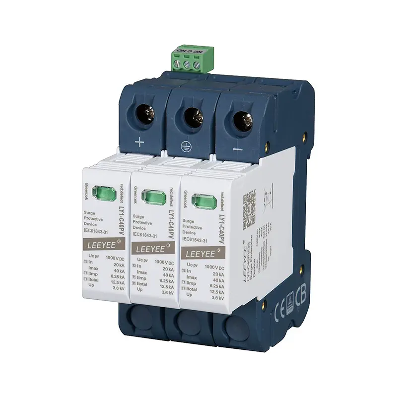
LY1-C40/3(S)+1 Pluggable Multi-Pole SPD
A DIN-rail Type 2 SPD option for three-phase distribution boards and electrical panels using a 3P+N / 3+1 protection arrangement.
Exact Uc, pole configuration, protection mode, certificate scope and backup-protection requirements must be confirmed for the required model and project.
Type 2 SPD Buyer Checklist
Send these details when requesting a quotation or technical model match. They reduce back-and-forth and help prevent incorrect substitutions.
- Destination market and required standard
- Main DB, sub-DB, control panel or OEM assembly
- Nominal AC system voltage
- Single-phase or three-phase
- TT, TN-S, TN-C-S, TN-C or IT system
- 1P+N, 2P, 3P, 3P+N or 4P requirement
- Required Uc or system voltage condition
- Required In and Imax
- Required Up
- Prospective short-circuit current if known
- Backup fuse or breaker condition
- Visual indicator or remote signal requirement
- Pluggable or monoblock construction
- Certificate and test-report requirement
- OEM logo, packaging or labeling requirement
- Order quantity and delivery schedule
Common Type 2 SPD Selection Mistakes
Choosing only by Imax
A high Imax cannot compensate for incorrect Uc, poor Up coordination, unsuitable protection mode or inadequate short-circuit coordination.
Assuming Type 2 means the same worldwide
IEC Type 2 and UL Type 2 belong to different standards frameworks. Certification must be checked separately.
Choosing pole count from phase count alone
A four-module SPD can use different internal circuits. Check 3+1 versus 4+0 and the N-PE protection path.
Ignoring conductor length
Declared SPD Up is not automatically the voltage seen by the load after long wiring adds inductive voltage.
Adding a random backup MCB
Backup protection should come from manufacturer coordination data, not a generic SPD-to-breaker formula.
Using an AC SPD on PV DC
PV DC protection requires an SPD specifically designed and rated for the photovoltaic DC circuit.
Type 2 SPD FAQ
What does Type 2 SPD mean?
In the IEC framework, a Type 2 SPD is a surge protective device with Type 2 surge-current test duty based on an 8/20 μs waveform. It is commonly used at distribution and sub-distribution level to limit induced lightning and switching transient overvoltages.
Is a Type 2 SPD the same as a Class II SPD?
IEC and EN product catalogs often use Class II wording for devices associated with Type 2 8/20 μs duty. For procurement, verify the actual standard and test declaration rather than relying only on the Class II label.
Where should a Type 2 SPD be installed?
Type 2 SPDs are commonly installed in main distribution boards where Type 1 duty is not required, sub-distribution boards, industrial panels, machine cabinets and control panels.
Can a Type 2 SPD be used without a Type 1 SPD?
Yes, where Type 1 lightning-current protection is not required at that installation point and applicable electrical rules permit Type 2 protection. If partial direct lightning current may enter the installation, Type 1 or Type 1+2 protection may be required upstream.
What kA rating should a Type 2 SPD have?
There is no universal kA value for every installation. Compare In and Imax separately and also check Uc, Up, earthing system, protection mode, short-circuit conditions and project requirements.
Is 40 kA better than 20 kA for a Type 2 SPD?
A higher discharge-current rating can provide greater surge-current capacity under its defined test conditions, but it does not automatically make the SPD better for a specific installation. Voltage compatibility, Up, repeated-duty performance, wiring and short-circuit coordination also matter.
Does a Type 2 SPD need a circuit breaker?
It depends on the SPD and installation. Some designs coordinate with the existing upstream protective device, while others require a dedicated fuse or breaker. Follow manufacturer backup-protection and short-circuit coordination instructions.
What is the difference between Uc and Up?
Uc is the maximum continuous operating voltage for an IEC SPD. Up is the declared voltage protection level during surge operation. Uc determines continuous voltage suitability, while Up helps evaluate transient voltage reaching downstream equipment.
What is the difference between In and Imax?
In is the nominal discharge current used for defined Type 2 duty testing. Imax is the maximum discharge current declared for the Type 2 SPD under the applicable test framework.
Can I use an IEC Type 2 SPD in a U.S. project?
Only if the project and authority having jurisdiction accept the actual product certification and installation conditions. IEC Type 2 wording does not establish UL 1449 Type 2 certification.
Can a Type 2 SPD protect against a direct lightning strike?
A standard IEC Type 2 SPD is not a substitute for Type 1 lightning-current protection where partial direct lightning current can enter the electrical installation. Type 2 normally addresses induced, switching and residual surge energy.
Continue the Type 2 SPD Selection Process
Need a Type 2 SPD for a Distribution Board or OEM Panel?
Send LEEYEE the system voltage, phase arrangement, earthing system, installation position, required Uc, In, Imax, Up, pole configuration and certification requirement. We can help narrow the suitable Type 2 SPD before quotation.